Z64-WL1835MODWiFi and Bluetooth Module
Texas Instruments Incorporated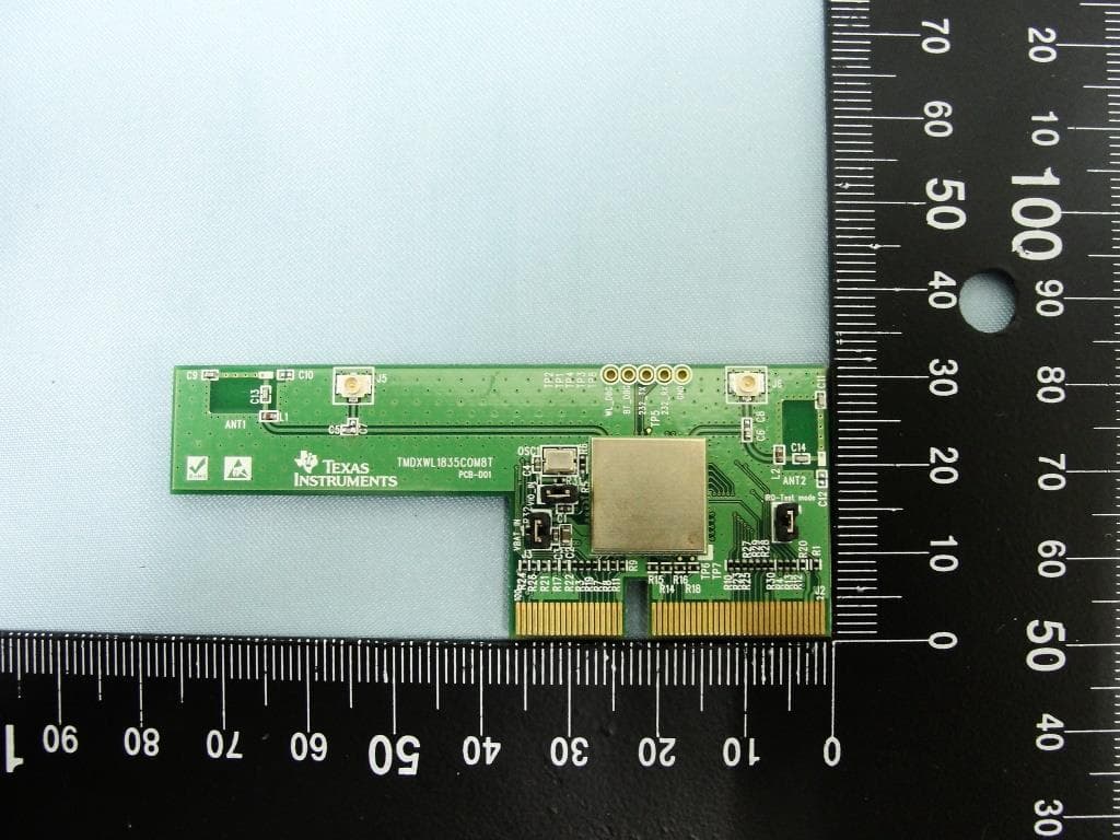
Click to zoom
Application Details
- Equipment Class
- DSS - Part 15 Spread Spectrum Transmitter
- Date of Grant
- Nov 07, 2013
- Application Purpose
- Original Equipment
- Date of Application
- Nov 07, 2013
- Equipment Note
- WiFi and Bluetooth Module
- Frequency Range
- 2402.00000000 - 2480.00000000
- Country
- United States
Documents & Files
Document Text
Text extracted from the exhibit documents filed with the FCC. Open a document above to read the original.
Users Manual
Thank you for purchasing this Texas Instruments SimpleLink ™ Wi-Fi ® CC3000 Evaluation Module To get started, and for questions, please visit: Wireless Connectivity Wiki: www.ti.com/cc3000wiki User guides, sample applications, software available E2E Forum: www.ti.com/cc3000forum Engineer-to-engineer technical support EVALUATION BOARD/KIT/MODULE (EVM) WARNINGS, RESTRICTIONS AND DISCLAIMERS For Feasibility Evaluation Only, in Laboratory/Development Environments. Unless otherwise indicated, this EVM is not a fin- ished electrical equipment and not intended for consumer use. It is intended solely for use for preliminary feasibility evaluation in laboratory/development environments by technically qualified electronics experts who are familiar with the dangers and application risks associated with handling electrical mechanical components, systems and subsystems. It should not be used as all or part of a finished end product Your Sole Responsibility and Risk. You acknowledge, represent and agree that: 1. You have unique knowledge concerning Federal, State and local regulatory requirements (including but not limited to Food and Drug Administration regulations, if applicable) which relate to your products and which relate to your use (and/or that of your employees, affiliates, contractors or designees) of the EVM for evaluation, testing and other purposes. 2. You have full and exclusive responsibility to assure the safety and compliance of your products with all such laws and other ap- plicable regulatory requirements, and also to assure the safety of any activities to be conducted by you and/or your employees, affiliates, contractors or designees, using the EVM. Further, you are responsible to assure that any interfaces (electronic and/or mechanical) between the EVM and any human body are designed with suitable isolation and means to safely limit accessible leakage currents to minimize the risk of electrical shock hazard. 3. You will employ reasonable safeguards to ensure that your use of the EVM will not result in any property damage, injury or death, even if the EVM should fail to perform as described or expected. 4. You will take care of proper disposal and recycling of the EVM’s electronic components and packing materials. Certain Instructions. It is important to operate this EVM within TI’s recommended specifications and environmental considerations per the user guidelines. Exceeding the specified EVM ratings (including but not limited to input and output voltage, current, power, and environmental ranges) may cause property damage, personal injury or death. If there are questions concerning these ratings please contact a TI field representative prior to connecting interface electronics including input power and intended loads. Any loads applied outside of the specified output range may result in unintended and/or inaccurate operation and/or possible permanent damage to the EVM and/or interface electronics. Please consult the EVM User’s Guide prior to connecting any load to the EVM output. If there is uncertainty as to the load specification, please contact a TI field representative. During normal operation, some circuit components may have case temperatures greater than 60oC as long as the input and output are maintained at a normal ambient operating temperature. These components include but are not limited to linear regulators, switching transistors, pass transistors, and current sense resistors which can be identified using the EVM schematic located in the EVM User’s Guide. When placing measurement probes near these devices during normal operation, please be aware that these devices may be very warm to the touch. As with all electronic evaluation tools, only qualified personnel knowledgeable in electronic measurement and diagnostics normally found in development environments should use these EVMs Agreement to Defend, Indemnify and Hold Harmless. You agree to defend, indemnify and hold TI, its licensors and their represen- tatives harmless from and against any and all claims, damages, losses, expenses, costs and liabilities (collectively, “Claims”) arising out of or in connection with any use of the EVM that is not in accordance with the terms of the agreement. This obligation shall apply wheth- er Claims arise under law of tort or contract or any other legal theory, and even if the EVM fails to perform as described or expected. Safety-Critical or Life-Critical Applications. If you intend to evaluate the components for possible use in safety critical applications (such as life support) where a failure of the TI product would reasonably be expected to cause severe personal injury or death, such as devices which are classified as FDA Class III or similar classification, then you must specifically notify TI of such intent and enter into a separate Assurance and Indemnity Agreement. The platform bar is a trademark of Texas Instruments. © 2012 Texas Instruments Incorporated. 9 Printed on recycled paper SZZZ078 TI Worldwide Technical Support INTERNET TI Semiconductor Product Information Center Home Page www.support.ti.com TI Semiconductor Knowledge Base Home Page www.support.ti.com/sc/knowledgebase PRODUCT INFORMATION CENTERS Americas Phone +1 (972) 644-5580 Brazil Phone 0800-891-2616 Mexico Phone 0800-670-7544 Fax +1 (972) 927-6377 Internet/Email www.ti.com/ww/en/pic/PIC-Americas.htm Europe, Middle East, and Africa Phone European Free Call 00800-ASK TEXAS (00800 275 83927) International +49 (0) 8161 80 2121 Russian Support +7 (4) 95 98 10 701 NOTE: The European Free Call (Toll Free) number is not active in all countries. If you have technical difficulty calling the free call number please use the international number above. Fax +(49) (0) 8161 80 2045 Internet www.ti.com/ww/eu/customer_support/index.htm Asia Phone International +91-80-41381665 Domestic Toll Free Number Australia 1-800-999-084 China 800-820-8682 Hong Kong 800-96-5941 India 1-800-425-7888 Korea 080-551-2804 Malaysia 1-800-80-3973…
Text truncated - open the document above for the full version.
Users Manual
WL18MOD Product Certification 1 WL18MOD Product Certification Introduction The TI WL1835MODGA Module is now certified for FCC, IC, CE and TELEC as well as by the Wi-Fi Alliance®. TI Customers that build products based on the TI WL1835MODGA module can save, in testing cost, and time per product family. •This feature can realize customers savings of over $25K per model family along with avoidance of test cycling and support resources. •For more details please refer to the information below. Certifications & Compliance •Certified for United States •Tests reports recognized by other countries for filing •Certified for Canada •Accepts FCC test reports for filing certifications •CE Radio Approval •ETSI testing is recognized by 40+ countries for filing •Certified for Japan •TELEC Test reports are available FCC [1] Certification Module The TI WL1835MODGA module is designed to be certified for FCC as a single-modular transmitter (Approval not yet granted). •The TI WL1835MODGA is designed to be a FCC certified radio module that carries a “Modular” grant (Approval not yet granted). •Certified radio modules complies to the “Intentional Radiator” portion (Part 15c) for FCC certification: Part 15.247 Transmitter tests. •Part 15.247 transmitter tests consists of •AC Power Conducted Emissions •Radiated Emissions •Band Edge Measurements •6dB bandwidth •Conducted Power •Power Spectral Density •Meeting Antenna Requirements •The customer can refer to TI's WL1835MOD FCC certification, once available (Not Yet Approved). •“Modular” certified radio modules are allowed for integration into multiple host end products by the FCC Useful Links: WL18MOD Product Certification 2 WL1835MODGA FCC modular grant (Not Yet Available) App note on modular FCC certification [2] Host End Products •An end product, incorporating WL1835MODGA module, does not require additional testing or authorization for the WiFi transmitter as long as •An antenna of the same or similar type and equal or less gain to the antenna used in the WL1835MODGA COM8 Board (WL1835MODCOM8A [3] ) is used on the product •Any restrictions found in the grants are followed in the OEM’s end product integrating the TI module. •Host end products can use the FCC ID of the certified module as the FCC ID of the host end product •A label displaying the module’s FCC ID must be affixed and visible on the host end product for approval •FCC IDs are required for host end products with radio transmitters Customer's Responsibilities •The manufacturer of the host end products are still responsible for any additional testing covered by the Class of the product. Device Class A and B. •Customers still need to take their products through other FCC/IC testing such as unintentional radiators (FCC sub part 15B) including any other required regionally driven end product certifications including but not limited to EU directives. FCC Part 15 Cert. Process/Flow Step 1Step 2Step 3Step 4 Sub Part A •General Provisions & Definitions Sub Part B •Unintentional Radiators •Devices, whose purpose is not to produce radio waves, but which do anyway, such as computers. Sub Part C •Intentional Radiators •Devices designed to produce coherent radio waves, such as small transmitters •Customers can reuse TI's Certifications Device Class A and B •Additional testing for intended use Additional testing maybe required for Host end product type. •Class A: Digital Device for use in a commercial, industrial or business environment. •Class B: Digital Device for use in a residential environment not withstanding use in commercial, business and industrial environments. •The FCC allows for self-declaration for Part B so the process should be relatively painless The customer can refer to the Electronic Code of Federal Regulation for Telecommunications, Part 15: Radio Frequencies Devices [4] for more details on each sub part. WL18MOD Product Certification 3 IC [5] Certification The TI WL1835MODGA module is designed to be certified for Industry Canada (IC) as a single-modular transmitter (Approval not yet granted). •For Industry Canada, the TI WL1835MODGA module is designed to meet modular approval and labeling requirements ((Approval not yet granted). •Industry Canada follows the same testing and rules as the FCC in regards to certified modules in authorized equipment. Host Product •The IC ID of TI WL1835MODGA (once available) can be used on the Host End Product with a label that is visible, and displays the IC ID of the WL1835MODGA module •The customer can refer to TI's WL1835MODGA IC certification, once available (Not Yet Approved). Useful Links: WL1835MODGA IC modular grant (Not Yet Available) App note on IC modular certification (see section 3.2 inside) [6] ETSI [7] /CE Certification WL1835MODGA is designed to CE Certified The TI WL1835MODGA module is designed to have certifications to the appropriate EU radio and EMC directives summarized in TI’s Declaration of Conformity (Not Yet Available) and evidenced by the CE Mark (Not Yet Available). This certification eliminates EU RTTE based retesting efforts, resulting in savings of more than $25K per product model family including test cycling and support resource benefits. For the conformity implications of attaching the antenna to a module that already has a conformance document - From section 1.3.1 of the Guide to the R&TTE Directive 1999/5/EC [8] “Manufacturers who place on the market products without an antenna or with an antenna that is intended to allow replacement have a responsibility to provide information on the general types and/or characteristics of antennas that may be used with their equipment in order that the overall radio equipment remains compliant. The guidance of the transmitter manufacturer has to be followed when they are installed.” It is important to note that •ETSI reports meet CE Radio Approval requirements of the R&TTE (Europe) directive •TI WL1835MODGA module is tested with ETSI EN300-328 radio tests which can be accepted by a number of cou…
Text truncated - open the document above for the full version.
Users Manual
WL1835MODCOM8AWLANMIMOand BT ModuleEvaluationBoardfor TI Sitara™ Platform User's Guide LiteratureNumber:SWRU359A September2013–RevisedOctober2013 Contents Preface.......................................................................................................................................3 1Introduction........................................................................................................................4 1.1Features..................................................................................................................4 1.2Applications..............................................................................................................5 1.3TI ModuleKey Benefits.................................................................................................5 2BoardPin Assignment.........................................................................................................6 2.1Pin Descriptions.........................................................................................................7 3ElectricalCharacteristics.....................................................................................................9 4AntennaCharacteristics.......................................................................................................9 4.1VSWR.....................................................................................................................9 4.2Efficiency................................................................................................................10 5AntennaCharacteristics.....................................................................................................10 5.1RadioPattern...........................................................................................................10 6CircuitDesign...................................................................................................................14 6.1Schematic...............................................................................................................14 6.2Bill of Materials(BOM)................................................................................................15 7LayoutGuidelines.............................................................................................................16 7.1BoardLayout...........................................................................................................16 2 Tableof ContentsSWRU359A–September2013–RevisedOctober2013 SubmitDocumentationFeedback Copyright© 2013,TexasInstrumentsIncorporated Preface SWRU359A–September2013–RevisedOctober2013 ReadThisFirst AboutThisManual This user'sguidedescribeshow to use the TI WL1835MODCOM8Aboardto evaluatethe performanceof the TI WL1835MODGAmodule. RelatedDocumentationFromTexasInstruments • TI WiLink8Single-BandComboModule– Wi-Fi,BT, and BLE (SWRS152) • WiLink8 Wiki:http://www.ti.com/wilink8wiki If You NeedAssistance The primarysourcesof WL1835MODGAinformationare the device-specificdatasheetsand user’s guides.For the mostup-to-dateversionof the user’s guideand datasheets,go to http://www.ti.com/product/wl1835mod. Warning The WL1835MODCOM8Aboardis testedto complywith ETSI/R&TTE overtemperaturesfrom0 to +70°C. The WL1835MODCOM8Aboardis FCCand IC certified. This boardshouldnot be modifiedto operatein otherfrequencybandsotherthanwhatthey are designed for. FCC/ICRegulatorycompliance(WL1835MODCOM8Aboardonly) FCCPart 15 ClassA Compliant IC ICES-003ClassA Compliant 3 SWRU359A–September2013–RevisedOctober2013Preface SubmitDocumentationFeedback Copyright© 2013,TexasInstrumentsIncorporated User's Guide SWRU359A–September2013–RevisedOctober2013 WL1835MODCOM8AWLANMIMOand BT Module EvaluationBoardfor TI Sitara™ Platform 1Introduction The WL1835MODCOM8Adeviceis a WiFi ® MIMO,Bluetooth ® , andBluetoothLow Energy(BLE)module boardwith the TI WL1835MODGAmodule.WL1835MODGAis built-inTI WL1835IEEE802.11b/g/nand Bluetooth4.0 solutionsto providethe best WiFiandBluetoothcoexistenceinteroperabilityand power- savingtechnologiesfromTI. Figure1. WL1835MODCOM8ATop View 1.1Features • WLAN,Bluetooth, BLE on a moduleboard • 100-pinboardcard • Dimension76.0mm(L)x 31.0mm(W) • WLAN2.4 GHzSISO(20- and 40-MHzchannels),2.4-GHzMIMO(20-MHzchannels) • Supportfor BLE dual mode • Seamlessintegrationwith TI Sitaraand otherapplicationprocessors • Designfor TI AM335Xgeneral-purposeEVM • WLANandBluetooth, BLE coresare softwareand hardwarecompatiblewith priorWL127x,WL128x and CC256xofferings,for smoothmigrationto device. • SharedHCI transportforBluetoothand BLE overUARTand SDIOfor WLAN. • WiFi/Bluetoothsingleantennaco-existence • Built-inchip antenna • OptionalU.FLRF connectorfor external2.4-GHzbandantenna • Directconnectionto batteryusingexternalswitchingmodepowersupplysupporting4.8-Vto 2.9-V operation • VIO in the 1.8-Vdomain 4 WL1835MODCOM8AWLANMIMOand BT ModuleEvaluationBoardfor TISWRU359A–September2013–RevisedOctober2013 Sitara™ Platform SubmitDocumentationFeedback Copyright© 2013,TexasInstrumentsIncorporated www.ti.comIntroduction 1.2Applications • Internetof ThingsMultimedia • HomeElectronics • HomeAppliancesand WhiteGoods • Industrialand HomeAutomation • SmartGatewayand Metering • VideoConferencing • VideoCameraand Security 1.3TI ModuleKey Benefits • ReducesDesignOverhead:SingleWiLink8™ ModuleScalesAcrossWi-FiandBluetooth. • WLANHighThroughput:80 Mbps(TCP),100 Mbps(UDP) •Bluetooth4.0 + BLE (SmartReady) • WiFi-BluetoothSingleAntennaCoexistence • Low Power(30–50%LessthanPreviousGeneration) • Availableas Easy-to-UseFCC,ETSI,and TelecCertifiedModule • LowerManufacturingCosts,SavingBoardSpaceand MinimizingRF Expertise • AM335xLinux ® and Android™ ReferencePlatformAcceleratesCustomerDevelopmentand Timeto Market 5 SWRU359A–September2013–RevisedOctober2013WL1835MODCOM8AWLANMIMOand BT ModuleEvaluationBoardfor TI Sitara™ Platform SubmitDocumentationFeedback Copyright© 2013,TexasInstrumentsIncorporated BoardPin Assignmentwww.ti.com 2BoardPin As…
Text truncated - open the document above for the full version.
Cover Letter(s)
Texas Instruments Incorporated 12500 TI Boulevard, M/S 8669, Dallas, Texas 75243, United States Tel: 214-567-6695 ; Fax: 214-480-4400 Date: November 6, 2013 Request for Modular Approval for FCC ID: Z64-WL1835MOD Item Requirements EUT 1. The modular transmitter must have its own RF shielding. The module is equipped with its own shielding case. 2. The modular transmitter must have buffered modulation / data inputs. The module has buffer modulation / data inputs. 3. The modular transmitter must have its own power supply regulation. The module has its own power supply regulation. 4. The module must contain a permanently attached antenna, or contain a unique antenna connector, and be marketed and operated only with specific antenna(s), The requirements of antenna and spurious emission have been fulfilled. Please refer to the test report and the integrator instruction of this filing. 5. The modular transmitter must be tested in a stand-alone configuration. The module was tested on evaluation board, and it’s not inside of another device during testing 6. The modular transmitter must be labeled with its own FCC ID number. The module transmitter will be labeled with its own FCC ID, and for OEM integration the integration manual contains labeling instructions for the host device per Part 15.212 (vi) 7. The modular transmitter must comply with any specific rule or operating requirements applicable to the transmitter and the manufacturer must provide adequate instructions along with the module to explain any such requirements. The module approved transmitter complies with all applicable rules and the integration manual contains any specific requirements addressed to the integrator and/or to the end-user of the final end-product. 8. The modular transmitter must comply with any applicable RF exposure requirement. With the dedicated antenna (1.2 dBi) the module transmitter complies with the FCC RF exposure requirements for fixed and mobile applications.
External Photos
Photographs of EUT Report No.: EP383067 Brand Name: Texas Instruments / Model Name: WL1835MODGA SPORTON INTERNATIONAL INC. Page Number : 1 of 6 TEL : 886-3-327-3456 Report Issued Date : Nov. 06, 2013 FAX : 886-3-328-4978 Report Version : Rev. 02 FCC ID : Z64-WL1835MOD IC : 451I-WL1835MOD 720510 1. External Photograph of EUT EUT: WL1835MODGA WL1835MODGA WL1835MODGA Photographs of EUT Report No.: EP383067 Brand Name: Texas Instruments / Model Name: WL1835MODGA SPORTON INTERNATIONAL INC. Page Number : 2 of 6 TEL : 886-3-327-3456 Report Issued Date : Nov. 06, 2013 FAX : 886-3-328-4978 Report Version : Rev. 02 FCC ID : Z64-WL1835MOD IC : 451I-WL1835MOD 720510
ID Label/Location Info
Label Location EUT shielding case
ID Label/Location Info
TI Confidential – NDA Restrictions WG7835-T0A label 1 0 1 2 3 4 5 6 7 8 9 10 11 12 13 14 15 16 17 18 19 0 1 2 3 4 5 6 7 8 9 10 11 12 13 14 Model: WL1835MODGA FCC ID: Z64 - WL1835MOD IC: 451I - WL1835MOD LTC: 1212 013 1 R 201-135370 0700
Internal Photos
Photographs of EUT Report No.: EP383067 Brand Name: Texas Instruments / Model Name: WL1835MODGA SPORTON INTERNATIONAL INC. Page Number : 3 of 9 TEL : 886-3-327-3456 Report Issued Date : Nov. 08, 2013 FAX : 886-3-328-4978 Report Version : Rev. 03 FCC ID : Z64-WL1835MOD IC : 451I-WL1835MOD 720510 2. Internal Photograph of EUT Photographs of EUT Report No.: EP383067 Brand Name: Texas Instruments / Model Name: WL1835MODGA SPORTON INTERNATIONAL INC. Page Number : 4 of 9 TEL : 886-3-327-3456 Report Issued Date : Nov. 08, 2013 FAX : 886-3-328-4978 Report Version : Rev. 03 FCC ID : Z64-WL1835MOD IC : 451I-WL1835MOD 720510 Photographs of EUT Report No.: EP383067 Brand Name: Texas Instruments / Model Name: WL1835MODGA SPORTON INTERNATIONAL INC. Page Number : 5 of 9 TEL : 886-3-327-3456 Report Issued Date : Nov. 08, 2013 FAX : 886-3-328-4978 Report Version : Rev. 03 FCC ID : Z64-WL1835MOD IC : 451I-WL1835MOD 720510 Photographs of EUT Report No.: EP383067 Brand Name: Texas Instruments / Model Name: WL1835MODGA SPORTON INTERNATIONAL INC. Page Number : 6 of 9 TEL : 886-3-327-3456 Report Issued Date : Nov. 08, 2013 FAX : 886-3-328-4978 Report Version : Rev. 03 FCC ID : Z64-WL1835MOD IC : 451I-WL1835MOD 720510 Photographs of EUT Report No.: EP383067 Brand Name: Texas Instruments / Model Name: WL1835MODGA SPORTON INTERNATIONAL INC. Page Number : 7 of 9 TEL : 886-3-327-3456 Report Issued Date : Nov. 08, 2013 FAX : 886-3-328-4978 Report Version : Rev. 03 FCC ID : Z64-WL1835MOD IC : 451I-WL1835MOD 720510 Photographs of EUT Report No.: EP383067 Brand Name: Texas Instruments / Model Name: WL1835MODGA SPORTON INTERNATIONAL INC. Page Number : 8 of 9 TEL : 886-3-327-3456 Report Issued Date : Nov. 08, 2013 FAX : 886-3-328-4978 Report Version : Rev. 03 FCC ID : Z64-WL1835MOD IC : 451I-WL1835MOD Bluetooth & WLAN Antenna 2 Photographs of EUT Report No.: EP383067 Brand Name: Texas Instruments / Model Name: WL1835MODGA SPORTON INTERNATIONAL INC. Page Number : 9 of 9 TEL : 886-3-327-3456 Report Issued Date : Nov. 08, 2013 FAX : 886-3-328-4978 Report Version : Rev. 03 FCC ID : Z64-WL1835MOD IC : 451I-WL1835MOD WLAN Antenna 1
RF Exposure Info
SPORTON INTERNATIONAL INC. Page Number : 1 of 7 TEL : 886-3-327-3456 Report Issued Date : Nov. 06, 2013 FAX : 886-3-328-4978 Report Version : Rev. 02 FCC ID : Z64-WL1835MOD RF Exposure Evaluation Report Report No. : FA383067 RF Exposure Evaluation Report APPLICANT : Texas Instruments Incorporated EQUIPMENT : WiFi and Bluetooth Module BRAND NAME : Texas Instruments MODEL NAME : WL1835MODGA FCC ID : Z64-WL1835MOD STANDARD : 47 CFR Part 2.1091 We, SPORTON INTERNATIONAL INC., would like to declare that the device has been evaluated in accordance with 47 CFR Part 2.1091, and pass the limit. Without written approval of SPORTON INTERNATIONAL INC., the test report shall not be reproduced except in full. SPORTON INTERNATIONAL INC. No. 52, Hwa Ya 1 st Rd., Hwa Ya Technology Park, Kwei-Shan Hsiang, Tao Yuan Hsien, Taiwan, R.O.C. Approved by: Jones Tsai / Manager Reviewed by: Eric Huang / Deputy Manager SPORTON INTERNATIONAL INC. Page Number : 2 of 7 TEL : 886-3-327-3456 Report Issued Date : Nov. 06, 2013 FAX : 886-3-328-4978 Report Version : Rev. 02 FCC ID : Z64-WL1835MOD RF Exposure Evaluation Report Report No. : FA383067 Table of Contents 1. ADMINISTRATION DATA ........................................................................................................................... 4 1.1. Testing Laboratory ............................................................................................................................. 4 1.2. Applicant ............................................................................................................................................ 4 1.3. Manufacturer ...................................................................................................................................... 4 2. DESCRIPTION OF EQUIPMENT UNDER TEST (EUT) ............................................................................. 5 3. MAXIMUM RF AVERAGE OUTPUT POWER AMONG PRODUCTION UNITS ........................................ 5 4. RF EXPOSURE LIMIT INTRODUCTION .................................................................................................... 6 5. RADIO FREQUENCY RADIATION EXPOSURE EVALUATION ............................................................... 7 5.1. Standalone Power Density Calculations............................................................................................ 7 5.2. Collocated Power Density Calculations ............................................................................................. 7 SPORTON INTERNATIONAL INC. Page Number : 3 of 7 TEL : 886-3-327-3456 Report Issued Date : Nov. 06, 2013 FAX : 886-3-328-4978 Report Version : Rev. 02 FCC ID : Z64-WL1835MOD RF Exposure Evaluation Report Report No. : FA383067 Revision History REPORT NO. VERSION DESCRIPTION ISSUED DATE FA383067 Rev. 01 Initial issue of report Nov. 04, 2013 FA383067 Rev. 02 Update equipment name Nov. 06, 2013 SPORTON INTERNATIONAL INC. Page Number : 4 of 7 TEL : 886-3-327-3456 Report Issued Date : Nov. 06, 2013 FAX : 886-3-328-4978 Report Version : Rev. 02 FCC ID : Z64-WL1835MOD RF Exposure Evaluation Report Report No. : FA383067 1. Administration Data 1.1. Testing Laboratory Test Site SPORTON INTERNATIONAL INC. Test Site Location No. 52, Hwa Ya 1 st Rd., Hwa Ya Technology Park, Kwei-Shan Hsiang, Tao Yuan Hsien, Taiwan, R.O.C. TEL: +886-3-327-3456 FAX: +886-3-328-4978 1.2. Applicant Company Name Texas Instruments Incorporated Address 12500 TI Boulevard M/S 8751. Dallas, TX 75243. 1.3. Manufacturer Company Name Jorjin Technologies Inc. Address 17F, No.239, Sec. 1, Datong Rd, Xizhi Dist. New Taipei City 221, Taiwan. R.O.C. SPORTON INTERNATIONAL INC. Page Number : 5 of 7 TEL : 886-3-327-3456 Report Issued Date : Nov. 06, 2013 FAX : 886-3-328-4978 Report Version : Rev. 02 FCC ID : Z64-WL1835MOD RF Exposure Evaluation Report Report No. : FA383067 2. Description of Equipment Under Test (EUT) Product Feature & Specification EUT Type WiFi and Bluetooth Module Brand Name Texas Instruments Model Name WL1835MODGA FCC ID Z64-WL1835MOD Wireless Technology and Frequency Range WLAN 2.4GHz Band: 2412 MHz ~ 2462 MHz Bluetooth: 2402 MHz ~ 2480 MHz Mode •802.11b/g/n HT20/HT40 •Bluetooth v3.0+EDR,Bluetooth v4.0+LE Antenna Type WLAN: Chip Antenna Bluetooth: Chip Antenna EUT Stage Production Unit Remark: The above EUT's information was declared by manufacturer. Please refer to the specifications or user's manual for more detailed description. 3. Maximum RF average output power among production units Mode / Band Average Power (dBm) 1Mbps (GFSK) 2Mbps (π/4-DQPSK) 3Mbps (8-DPSK) BT4.0-LE (GFSK) 2.4 GHz Bluetooth 13.0 9.0 9.0 10.0 Band / Frequency (MHz) IEEE 802.11 Average Power (dBm) Ant 0 Ant 1 Ant 0+1 11b 11g HT20 HT40 11b 11g HT20 HT40 HT20 2.4GHz Band 2412 19.0 17.0 17.0 16.5 16.0 15.5 14.5 18.0 2422 15.0 2437 19.0 17.0 2452 15.0 2462 17.0 SPORTON INTERNATIONAL INC. Page Number : 6 of 7 TEL : 886-3-327-3456 Report Issued Date : Nov. 06, 2013 FAX : 886-3-328-4978 Report Version : Rev. 02 FCC ID : Z64-WL1835MOD RF Exposure Evaluation Report Report No. : FA383067 4. RF Exposure Limit Introduction According to ANSI/IEEE C95.1-1992, the criteria listed in Table 1 shall be used to evaluate the environmental impact of human exposure to radio frequency (RF) radiation as specified in §1.1310. The MPE was calculated at 20 cm to show compliance with the power density limit. The following formula was used to calculate the Power Density: 퐒= 퐏퐆 ퟒ훑퐑 ퟐ Where: S = Power Density P = Output Power at Antenna Terminals G = Gain of Transmit Antenna (linear gain) R = Distance from Transmitting Antenna SPORTON INTERNATIONAL INC. Page Number : 7 of 7 TEL : 886-3-327-3456 Report Issued Date : Nov. 06, 2013 FAX : 886-3-328-4978 Report Version : Rev. 02 FCC ID : Z64-WL1835MOD RF Exposure Evaluation Report Report No. : FA383067 5. Radio Frequency Radiation Exposure Evaluation 5.1. Standalone Power Density Calculations Band Frequency (MHz) Antenna Gain (dBi) Maximum Power (dBm) Power Densit…
Text truncated - open the document above for the full version.
Test Report
SPORTON INTERNATIONAL INC. Page Number : 1 of 85 TEL : 886-3-327-3456 Report Issued Date : Nov. 06, 2013 FAX : 886-3-328-4978 Report Version : Rev. 02 FCC ID : Z64-WL1835MOD FCC RF Test Report Report No. : FR383067A FCC RF Test Report APPLICANT : Texas Instruments Incorporated EQUIPMENT : WiFi and Bluetooth Module BRAND NAME : Texas Instruments MODEL NAME : WL1835MODGA FCC ID : Z64-WL1835MOD STANDARD : FCC Part 15 Subpart C §15.247 CLASSIFICATION : (DSS) Spread Spectrum Transmitter The product was received on Aug. 30, 2013 and testing was completed on Oct. 10, 2013. We, SPORTON INTERNATIONAL INC., would like to declare that the tested sample has been evaluated in accordance with the procedures and shown to be compliant with the applicable technical standards. The test results in this report apply exclusively to the tested model / sample. Without written approval of SPORTON INTERNATIONAL INC., the test report shall not be reproduced except in full. Review…
Text truncated - open the document above for the full version.
Contact Information
Applicant
Marian Kost(Product Line Manager, Connectivity)
Test Firm
Sporton International Inc.Alex Chen
Technical Specifications
| # | Rule Parts | Frequency Range | Power Output |
|---|---|---|---|
| 1 | 15C | 2.40 GHz - 2.48 GHz | 15.10 mW |
Other Applications from Texas Instruments Incorporated
Z64-CC33SBMOD
Jul 17, 2025802.11 b/g/n/ax WLAN + BLE Radio Module
Equipment Class
DTS - Digital Transmission System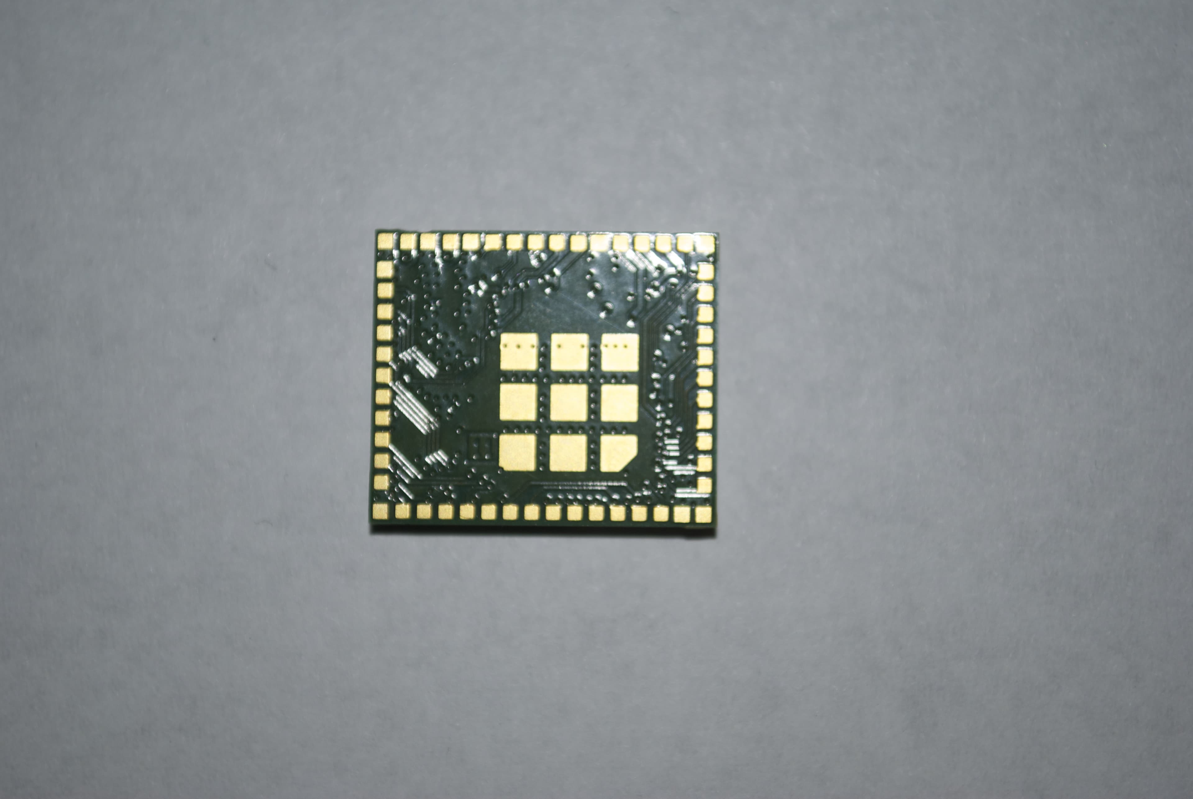
Z64-CC3200MODR1
Oct 08, 2014Radio Module
Equipment Class
DTS - Digital Transmission System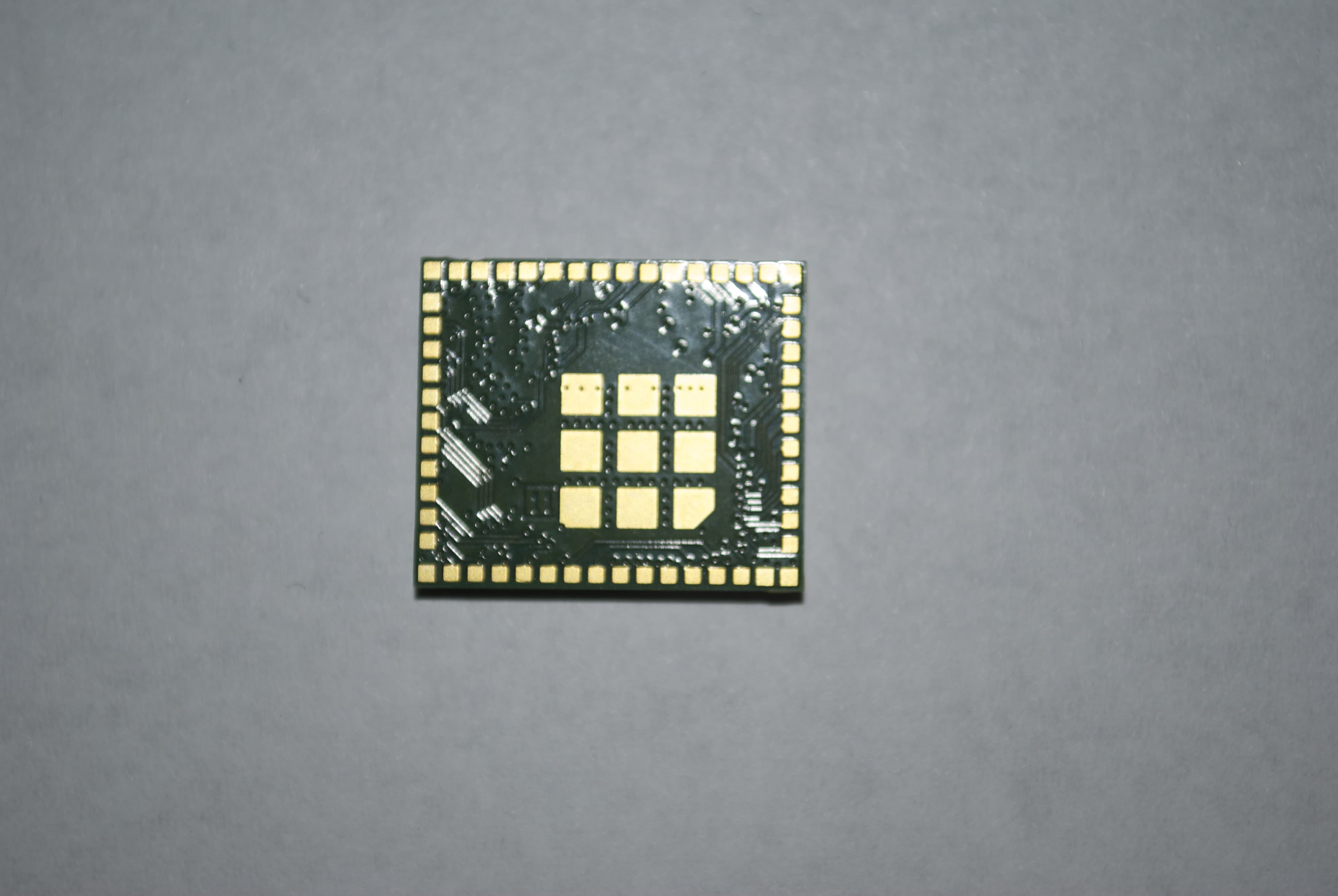
Z64-CC3100MODR1
Oct 08, 2014Radio Module
Equipment Class
DTS - Digital Transmission System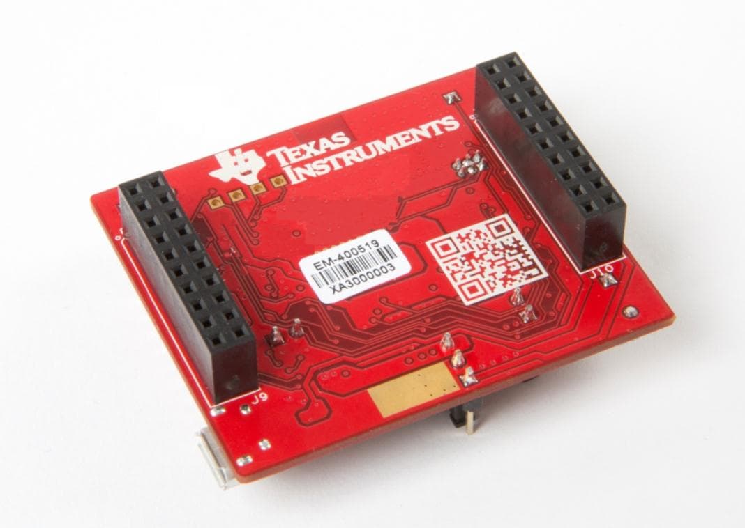
Z64-CC3100KITA
May 06, 2014Evaluation board
Equipment Class
DTS - Digital Transmission System
Z64-CC3200KITA
May 06, 2014Evaluation board
Equipment Class
DTS - Digital Transmission System