Z64EXP4F6137R9The MSP-EXP430F6137R9 is a development tool for TI less than 1GHz CC430F6137 System-on-Chip.
Texas Instruments Incorporated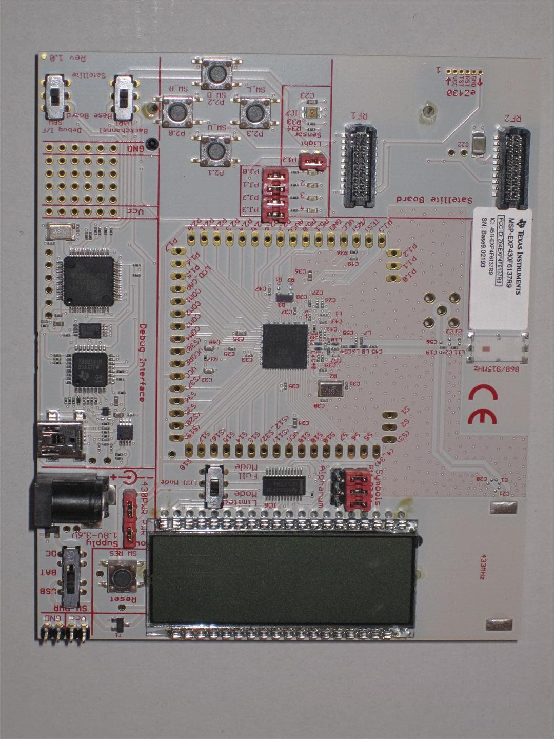
Click to zoom
Application Details
- Equipment Class
- DXX - Part 15 Low Power Communication Device Transmitter
- Date of Grant
- Feb 12, 2013
- Application Purpose
- Original Equipment
- Date of Application
- Feb 07, 2013
- Equipment Note
- The MSP-EXP430F6137R9 is a development tool for TI less than 1GHz CC430F6137 System-on-Chip.
- Frequency Range
- 903.49000000 - 926.49000000
- Country
- United States
Documents & Files
Document Text
Text extracted from the exhibit documents filed with the FCC. Open a document above to read the original.
Users Manual
MSP-EXPCC430RFxExperimenterKit ECCN5A002A1A User's Guide LiteratureNumber:SLAU460 November2012 Contents 1MSP-EXPCC430RFxExperimenterKitOverview......................................................................4 1.1Overview..................................................................................................................4 1.2KitContents..............................................................................................................8 2GettingStartedWiththeMSP-EXPCC430RFxExperimenterKit................................................8 2.1HardwarePreparation..................................................................................................8 2.2SoftwarePreparation...................................................................................................9 2.3MSP-EXPCC430RFxUserExperience.............................................................................10 2.4MSP-EXPCC430RFxFirmwareApplications......................................................................10 2.5CC430WirelessNetworkGUI........................................................................................11 3MSP-EXPCC430RFxExperimenterKitHardware....................................................................12 3.1MSP-EXP430F6137RxHardwareDescription.....................................................................12 3.2MSP-EXP430F5137RxHardwareDescription.....................................................................12 3.3Schematics.............................................................................................................13 3.4PCBLayout.............................................................................................................17 4MSP-EXPCC430RFxExperimenterKitFirmware....................................................................19 4.1ImportProjectin CodeComposerStudio...........................................................................19 4.2OpenProjectin IAREmbeddedWorkbench.......................................................................19 4.3SimpliciTI™RFProtocol..............................................................................................19 4.4SimpliciTIConfigurationfortheMSP-EXPCC430RFxUserExperience.......................................19 4.55xx/6xxCoreLibraries................................................................................................20 5MSP-EXPCC430RFxExperimenterKitSoftware.....................................................................20 5.1Requirements...........................................................................................................20 6References.......................................................................................................................20 7BillsofMaterials(BOM)......................................................................................................21 2 TableofContentsSLAU460– November2012 SubmitDocumentationFeedback Copyright© 2012,TexasInstrumentsIncorporated www.ti.com ListofFigures 1MSP-EXPCC430RFxExperimenterKit– MSP-EXP430F6137RxBaseBoard(Front)............................5 2MSP-EXPCC430RFxExperimenterKit– MSP-EXP430F6137RxBaseBoard(Back)............................6 3MSP-EXPCC430RFxExperimenterKit– MSP-EXP430F5137RxSatelliteBoard(Front)........................7 4MSP-EXPCC430RFxExperimenterKit– MSP-EXP430F5137RxSatelliteBoard(Back)........................7 5MSP-EXP430F6137RxBaseBoardHardware........................................................................12 6MSP-EXP430F5137RxSatelliteBoardHardware....................................................................12 7MSP-EXP430F6137RxBaseBoardSchematic– Page1...........................................................13 8MSP-EXP430F6137RxBaseBoardSchematic– Page2...........................................................14 9MSP-EXP430F6137RxBaseBoardSchematic– Page3...........................................................15 10MSP-EXP430F5137RxSatelliteBoardSchematic....................................................................16 11MSP-EXP430F6137RxBaseBoardLayout...........................................................................17 12MSP-EXP430F5137RxSatelliteBoardLayout........................................................................18 ListofTables 1MSP-EXP430F6137R9BaseBoard(HW-V2.1)BOM................................................................21 2MSP-EXP430F5137R9TSatelliteBoard(HW-V2.0)BOM...........................................................25 3MSP-EXP430F6137R4BaseBoard(HW-V2.1)BOM................................................................26 4MSP-EXP430F5137R4TSatelliteBoard(HW-V2.0)BOM...........................................................30 3 SLAU460– November2012ListofFigures SubmitDocumentationFeedback Copyright© 2012,TexasInstrumentsIncorporated User's Guide SLAU460– November2012 MSP-EXPCC430RFxExperimenterKitUser’s Guide 1MSP-EXPCC430RFxExperimenterKitOverview 1.1Overview TheMSP-EXPCC430RFxExperimenterKitis thecompletesub-GHzdevelopmentplatformfortheCC430 devicesfromtheMSP430™family.Thekitprovidestwosub-GHzwirelessmodules:theMSP- EXP430F6137RxBaseBoardwiththeCC430F6137,andtheMSP-EXP430F5137RxSatelliteBoardwith theCC430F5137.Outofthebox,thetwomodulesenabledemonstrationofa SimpliciTI™wirelesssensor networkandtakefulladvantageofa highly-integratedLCDandPCconnection.Additionally,thekitalso enablesa completedevelopmentandprototypingenvironmenttodesigna wirelessapplication. MSP430,SimpliciTIaretrademarksofTexasInstruments. Allothertrademarksarethepropertyoftheirrespectiveowners. 4 MSP-EXPCC430RFxExperimenterKitUser’s GuideSLAU460– November2012 SubmitDocumentationFeedback Copyright© 2012,TexasInstrumentsIncorporated www.ti.comMSP-EXPCC430RFxExperimenterKitOverview Figure1.MSP-EXPCC430RFxExperimenterKit– MSP-EXP430F6137RxBaseBoard(Front) 5 SLAU460– November2012MSP-EXPCC430RFxExperimenterKitUser’s Guide SubmitDocumentationFeedback Copyright© 2012,TexasInstrumentsIncorporat…
Text truncated - open the document above for the full version.
Block Diagram
MSP-EXP430F6137R9 CC430F6137 SoC Matching Antenna MCU 26MHz XTAL LEDs, Button, Light Sensor Emulator & Backchannel UART LC Display with Bus switch Connector for MSP- EXP430F5137RF9 (optional) USB
ID Label/Location Info
Description of label for the Texas Instruments MSP-EXP430F6137R9: - Relevant sticker on PCB o Vendor: Texas Instruments o Product number/name: MSP-EXP430F6137R9 o FCC ID: Z64EXP4F6137R9 Approx. 120mm FCC / IC Cert. Document Label Description of Labeling for MSP-EXP430F6137R9 Placement of FCC/IC Information on product back side (sticker on PCB) Label Material specification: Material Polyesterfoil with permanent acrylic adhesiv (UL-listed) Working temperature - 40°C bis + 150°C Resistant against Water, Humidity, Alcohol, Oil, Grease, Conventional household detergents FCC ID Z64EXP4F6137R9 This device complies with Part 15 of the FCC Rules. Operation is subject to the following two conditions: (1) This device may not cause harmful interference, and (2) This device must accept any interference received, including interference that may cause undesired operation This device complies with Industry Canada licence-exempt RSS standard(s). Operation is subject to the following two conditions:(1) this device may not cause interference, and (2) this device must accept any interference, including interference that may cause undesired operation of the device. Le présent appareil est conforme aux CNR d'Industrie Canada applicables aux appareils radio exempts de licence. L'exploitation est autorisée aux deux conditions suivantes : (1) l'appareil ne doit pas produire de brouillage, et (2) l'utilisateur de l'appareil doit accepter tout brouillage radioélectrique subi, même si le brouillage est susceptible d'en compromettre le fonctionnement.
Operational Description
Technical description for Texas Instruments MSP-EXP430F6137R9: The MSP-EXP430F6137R9 is an evaluation board for the CC430F6137 chip from Texas Instruments. The user needs to program the board with application code as described in the User’s Guide (SLAU460) or the corresponding Quick start guide of the MSP-EXPCC430RF9 kit of which this board is part of. The CC430F6137 System on Chip has a differential RF output. This transformed to a single ended, 50 ohm signal through passive components (capacitor/inductor) balun. The output of the balun is filtered to reduce harmonic radiation and then connected to a chip antenna. The chip antenna mounted on the board is 0920AT50A080 from JTI. The datasheet of the antenna is attached for further details. Frequency range: 902 – 928MHz (North America) Type of modulation: 2-GFSK Occupied bandwidth: 11.6 kHz Antenna connector: chip antenna mounted on PCB This evaluation board is intended for use for ENGINEERING DEVELOPMENT, DEMONSTRATION OR EVALUATION PURPOSES ONLY and is not considered by TI to be a finished end product fit for general consumer use.
Parts List/Tune Up Info
MSP-EXP430F6137R9 Bill of MaterialHW-V2.1 Date:27/09/11 PartValueTol.PackageManufacturerDetailsDistributorPart no. Capacitors C1n.m.C0402Johanson Technology500R07S2R2BV4T C2n.m.C0402 C32.2pFC0402Johanson Technology500R07S2R2BV4T C4100nF10%C0402 C51uF10%C0603 C610nF10%C0402 C733pF+/-0,25pFC0402 C833pF+/-0,25pFC0402 C922pF+/-0,25pFC0402 C1022pF+/-0,25pFC0402 C111uF10%C0603 C12100nF10%C0402 C13100nF10%C0402 C141uF10%C0603 C15100nF10%C0402 C16100nF10%C0402 C17100nF10%C0402 C181nF10%C0402 C19n.m.C0402 C20n.m.C0402 C21n.m.C0402 C22100uF20%C-POLB/3528 C23100nF10%C0603 C2468pFC0402 C2510uF20%C0603 C262pF+/-0,25pFC0402 C272pF+/-0,25pFC0402 C282pF+/-0,25pFC0402 C29470nF10%C0402 C3027pF+/-0,25pFC0402 C3127pF+/-0,25pFC0402 C3210uF10%C0603 C33100nF10%C0402 C3410uF20%C0603 C35100nF10%C0402 C3610uF20%C0603 C37100nF10%C0402 C38100nF10%C0402 C392pF+/-0,25pFC0402 C40100nF10%C0402 C412pF+/-0,25pFC0402 C42100nF10%C0402 C43100nF10%C0402 C44100nF10%C0402 C451.5pFC0402 C47100nF10%C0402 C4810uF20%C0603 C492.2nF+/-0,25pFC0402 C501pF+/-0,25pFC0402 C511.5pF+/-0,25pFC0402 C52100pF10%C0402 C531.5pF+/-0,25pFC0402 C541.5pF+/-0,25pFC0402 C556.8pF+/-0,25pFC0402 C56n.m.C0402 Diodes D11N4148WTSOD523 D2n.m.SOD523(PESD5V0U1UB) Inductors L1BLM15HG102SN1DL0402MurataFerrit, SMT, 250mABLM15HG102SN1D L2BLM15AX700SN1L0402MurataFerrit, SMT, 780mABLM15AX700SN1 L412nH5%L0402Johanson TechnologyL-07W12NJV4S L518nH5%L0402Johanson TechnologyL-07W18NJV4S L615nH5%L0402Johanson TechnologyL-07W15NJV4S L72,2nH+/-0,2nHL0402Johanson TechnologyL-07W2N2JV4S L815nH5%L0402Johanson TechnologyL-07W15NJV4S L912nH5%L0402Johanson TechnologyL-07W12NJV4S L1018nH5%L0402Johanson TechnologyL-07W18NJV4S L1115nHL0402Johanson TechnologyL-07C15NJV6T / L-07W15NJV6T Resistors R1n.m.1%R0402 R2n.m.1%R0402 R3470R1%R0402 R4750R1%R0402 R547kR1%R0402 R6100R1%R0402 R7100R1%R0402 R847kR1%R0402 R947kR1%R0402 R10100R1%R0402 R11100R1%R0402 R1233kR1%R0402 R1333R1%R0402 R1433R1%R0402 R151.5kR1%R0402 R166.8kR1%R0402 R173.3kR1%R0402 R181.5kR1%R0402 MSP-EXP430F6137R9-HW-V2.1_BOM.XLS, MSP-EXP430F6137R9page 1 of 2printed: 11/22/2012 MSP-EXP430F6137R9 Bill of MaterialHW-V2.1 Date:27/09/11 PartValueTol.PackageManufacturerDetailsDistributorPart no. R191.5kR1%R0402 R20100R1%R0402 R2115kR1%R0402 R2247kR1%R0402 R2347kR1%R0402 R243.3kR1%R0402 R253.3kR1%R0402 R26100kR1%R0402 R27100kR1%R0402 R2833kR1%R0402 R2910kR1%R0402 R3047kR1%R0402 R31100R1%R0402 R32270R1%R0402 R3356kR1%R0402 R340R1%R0402 R3556kR1%R0402 R3647kR1%R0402 R370R1%R0402 IC IC1CC430F6137IRGCS-PQFP-N64Texas Inst.CC430F6137 IC2TUSB3410VFVF32Texas Inst.TUSB3410VF IC3AT24C12810-TUTSSOP8AtmelAT24C12810-TU IC4TPS77301DGKMSO8Texas Inst.TPS77301DGK IC5TPD2E001DRLSOT533-5Texas Inst.TPD2E001DRL IC6SN74CBTLV3384DBQR24-SSOPTexas Inst.SN74CBTLV3384 IC7SFH5711SFH5711OsramSFH5711 IC8MSP430F1612IPMPM/PAG64Texas Inst.MSP430F16x Miscellaneous SW1JS203011CQNJS203011CQNC&K ComponentsJS203011CQN SW2J202011CQNJS202011CQNC&K ComponentsJS203011CQN SW3J202011CQNJS202011CQNC&K ComponentsJS203011CQN SW4J202011CQNJS202011CQNC&K ComponentsJS203011CQN SW_DFSM2JSMAB3FS-1002POmronB3FS-1002P SW_LFSM2JSMAB3FS-1002POmronB3FS-1002P SW_RFSM2JSMAB3FS-1002POmronB3FS-1002P SW_RESFSM2JSMAB3FS-1002POmronB3FS-1002P SW_UFSM2JSMAB3FS-1002POmronB3FS-1002P ANT10920AT50A080Johanson Technology868/915MHz0920AT50A080 ANT2n.m.Johanson Technology433MHz0433AT62A0020 BAT11028_KEYSTONEKeystone1028 BAT21028_KEYSTONEKeystone1028 LCD1FH-1138HTexas Inst.FH-1138H LED1APT1608QBC/D(blue)LED0603KingbrightblueAPT1608QBC/D LED2APT1608MGC(green)LED0603KingbrightgreenAPT1608MGC LED3APT1608SYCK(yellow)LED0603KingbrightyellowAPT1608SYCK LED4APT1608SRCPRV(red)LED0603KingbrightredAPT1608SRCPRV Q1FT10A-12,0/16-30-30/275032-4PINCoftech12MHz, 16pF, 30ppm Q2CTA531-26.000-16-10/10/ANX5032Compotekhf crystalCTA531-26.000-16-10/10/A Q3CC7V-T1A_32,768kHz_12,5pF+/-20ppm3216Micro Crystalwatch crystalCC7V-T1A_32,768kHz_12,5pF T1SI2323DSSOT23-3VishayP-Channel 20-V MOSFET T2SI2323DSSOT23-3VishayP-Channel 20-V MOSFET P1n.m.1X16provided separately by EMS P2n.m.1X16provided separately by EMS P3n.m.1X16provided separately by EMS P4n.m.1X3provided separately by EMS P5n.m.1X3provided separately by EMS P6PINHD-1X31X3or identical in constructionMPE Garry0871-1-003-0-T-xso-1260 P7PINHD-1X31X3or identical in constructionMPE Garry0871-1-003-0-T-xso-1260 P8PINHD-1X21X2or identical in constructionMPE Garry0871-1-002-0-T-xso-1260 P9PINHD-1X21X2or identical in constructionMPE Garry0871-1-002-0-T-xso-1260 P10PINHD-1X21X2or identical in constructionMPE Garry0871-1-002-0-T-xso-1260 P11PINHD-1X31X3or identical in constructionMPE Garry0871-1-003-0-T-xso-1260 P12PINHD-1X21X2or identical in constructionMPE Garry0871-1-002-0-T-xso-1260 P13PINHD-2X42X4or identical in constructionMPE Garry0871-2-004-0-T-xso-1260 P14PINHD-1X21X2or identical in constructionMPE Garry0871-1-002-0-T-xso-1260 CON1n.m.BU-SMA-VSMA Female Connector CON2USB-MINI_2486_01USB-MINI_2486_01LUMBERG2486 01 CON3NEB21RDC_BUCHSE_2,1MMLUMBERGNEB 21 R CON4TFM-110-02-S-D-A-K10X2_SAMTEC_MSAMTECTFM-110-02-S-D-A-K CON5TFM-110-02-S-D-A-K10X2_SAMTEC_MSAMTECTFM-110-02-S-D-A-K CON6n.m.STL_31-06 SGUMPESTL_31-06 SGU PCB 1,283 mm x100mm x 120mm, FR4, TG150, see CC-EXP- 4306137RF9-HW-V1- PCB.pdf MSP-EXP430F6137R9-HW-V2.1_BOM.XLS, MSP-EXP430F6137R9page 2 of 2printed: 11/22/2012
Test Report
Nemko Oy P.O.Box 19, FI-02601 Espoo, Finland Street address: Perkkaantie 11, FI-02600 Espoo Telephone +358 (0)424 5454 1 Telefax +358 (0)9 5489 6371 TEST REPORT Date: ESPOO 25.05.2012 Page: 1 (22) Appendices Date of handing in: 12.05.2012 Number: 201497 No. 1 / 1 Tested by: Timo Hietala, Test Engineer Reviewed by: Janne Nyman, Compliance Specialist SORT OF EQUIPMENT: - MARKETING NAME: TYPE: MSP-EXP430F6137R9 MANUFACTURER: Texas Instruments CLIENT: Texas Instruments, Germany ADDRESS: Haggertystrasse 1, Freising, D-85356, Germany TELEPHONE: +49 8161 80 0 / Claus Kuch TEST LABORATORY: Nemko Oy FCC REG. NO. 359859 October 20, 2011 IC FILE NO. 2040F-1 December 1, 2010 SUMMARY: In regard to the performed tests the equipment under test fulfils the requirements defined in the test specifications, see page 2 for details The test results are valid for the tested unit only. Without a written permission of Nemko Oy it is allowed to copy this report as a whole, but not partially. Version f1.00 Type: MSP-EXP430F6137R9 Test report: 201497 Page 2 (22) Date 25.05.2012 Summary of performed tests and test results Section in CFR 47 Section in RSS-210 Result 15.249, a A2.9 (a) Field strength of fundamental PASS 15.249, a A2.9 (a) Band-edge compliance PASS 15.249, a A2.9 (a) Spurious radiated emissions PASS 15.215 (c) 20 dB bandwidth PASS 15.35 (c) RSS-Gen 4.5 Duty cycle PASS 15.207 Conducted emissions AC line Not tested 1) 1) Only battery operated. Explanations: PASS The EUT passed that particular test. FAIL The EUT failed that particular test. X The measurement was done, but there is no applicable performance criteria. Type: MSP-EXP430F6137R9 Test report: 201497 Page 3 (22) Date 25.05.2012 Contents Summary of performed tests and test results .......................................................................................... 2 1. EUT and Accessory Information ......................................................................................................... 4 1.1 EUT description ........................................................................................................................ 4 1.2 EUT and accessories ................................................................................................................ 4 2. Test setups .......................................................................................................................................... 5 3. Standards and measurement methods ............................................................................................... 6 4. Test results .......................................................................................................................................... 6 4.1 Field strength of fundamental ................................................................................................... 6 4.1.1 EUT operation mode ................................................................................................................. 6 4.1.2 Test method and limit ............................................................................................................... 6 4.1.3 Test results ............................................................................................................................... 7 4.2 Band-edge compliance ........................................................................................................... 10 4.2.1 EUT operation mode ............................................................................................................... 10 4.2.2 Test method and limit ............................................................................................................. 10 4.2.3 Limits and test results ............................................................................................................. 11 4.3 Spurious radiated emission .................................................................................................... 13 4.3.1 EUT operation mode ............................................................................................................... 13 4.3.2 Test method and limit ............................................................................................................. 13 4.3.3 Test results ............................................................................................................................. 14 4.4 20 dB Bandwidth ..................................................................................................................... 17 4.4.1 EUT operation mode ............................................................................................................... 17 4.4.2 Test data ................................................................................................................................. 17 4.5 Duty cycle ............................................................................................................................... 19 4.5.1 EUT operation mode ............................................................................................................... 19 4.5.2 Test method and limit ............................................................................................................. 19 4.5.3 Test data ................................................................................................................................. 19 5. List of test equipment ........................................................................................................................ 21 6. Photographs ...................................................................................................................................... 22 Type: MSP-EXP430F6137R9 Test report: 201497 Page 4 (22) Date 25.05.2012 1. EUT and Accessory Information 1.1 EUT description The EUT is a development platform for System on Chip. Alignment range: 902-928 MHz Channels: 1 Operating Voltage: 3.0 VDC Battery: 2xAA Antenna: Chip an…
Text truncated - open the document above for the full version.
Test Setup Photos
Type: MSP-EXP430F5137R9 Test report: 201498 Page 22 (22) Date 25.05.2012 6. Photographs Photograph 1, Radiated emissions test setup
Contact Information
Applicant
Marian Kost(Product Line Manager, Connectivity)
Technical Contact
Texas InstrumentsFritz R. Ward
[email protected](214) 567-9484
12500 TI Boulevard, M/S 8669 · Dallas · United States
Non-Technical Contact
Nemko USA, Inc.Zarah G. MacIvor
[email protected]214-629-5683
Test Firm
NEMKO OyJyrki Leino
Technical Specifications
| # | Rule Parts | Frequency Range | Power Output |
|---|---|---|---|
| 1 | 15C | 903.49 MHz - 926.49 MHz | - |
Other Applications from Texas Instruments Incorporated
Z64-CC33SBMOD
Jul 17, 2025802.11 b/g/n/ax WLAN + BLE Radio Module
Equipment Class
DTS - Digital Transmission System
Z64-CC3200MODR1
Oct 08, 2014Radio Module
Equipment Class
DTS - Digital Transmission System
Z64-CC3100MODR1
Oct 08, 2014Radio Module
Equipment Class
DTS - Digital Transmission System
Z64-CC3100KITA
May 06, 2014Evaluation board
Equipment Class
DTS - Digital Transmission System
Z64-CC3200KITA
May 06, 2014Evaluation board
Equipment Class
DTS - Digital Transmission System