Z64TRF7960AEVMThe TRF7960AEVM is a development platform for integrated analog front end and data-framing device operating as 13.56 MHz RFID/Near Field Communication system.
Texas Instruments Incorporated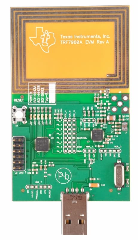
Click to zoom
Application Details
- Equipment Class
- DXT - Part 15 Low Power Transceiver, Rx Verified
- Date of Grant
- Feb 19, 2013
- Application Purpose
- Original Equipment
- Date of Application
- Feb 19, 2013
- Equipment Note
- The TRF7960AEVM is a development platform for integrated analog front end and data-framing device operating as 13.56 MHz RFID/Near Field Communication system.
- Frequency Range
- 13.56000000 - 13.56000000
- Country
- United States
Documents & Files
Document Text
Text extracted from the exhibit documents filed with the FCC. Open a document above to read the original.
Users Manual
TRF7960EVM User'sGuide LiteratureNumber:SLOU192C November2006–RevisedDecember2008 2SLOU192C–November2006–RevisedDecember2008 SubmitDocumentationFeedback Contents Preface...............................................................................................................................7 1IntroductionandDescription.....................................................................................11 1.1Description..................................................................................................................11 1.2EVMDefaultConfiguration................................................................................................11 2UsingtheEVM.........................................................................................................13 2.1Unpacking...................................................................................................................13 2.2HardwareDescription......................................................................................................14 2.3ConnectiontoaHostPC..................................................................................................18 3EVMSoftware..........................................................................................................19 3.1SoftwareInstallations......................................................................................................19 3.1.1VirtualCOMPortDriverInstallation.............................................................................19 3.1.2HardwareInstallation.............................................................................................19 3.1.3SoftwareGUIInstallation.........................................................................................20 3.2SoftwareInstallationforRev.AEVM....................................................................................22 3.2.1USBDriverInstallation............................................................................................22 3.2.2VirtualCOMPortDriverInstallation.............................................................................22 3.2.3HardwareInstallation.............................................................................................23 3.2.4SoftwareGUIInstallation.........................................................................................23 3.3SoftwareInterface..........................................................................................................25 3.3.1ProgramControlWindow(LowerRight-HandCorner).......................................................25 3.3.2ProtocolTabsWindow............................................................................................26 3.3.3UtilityTabsWindow...............................................................................................26 3.3.4FlagsWindow......................................................................................................26 3.3.5ChipStatusWindow..............................................................................................26 3.3.6Command(Request)Window...................................................................................26 3.3.7LogWindow........................................................................................................26 3.3.8TagDataWindow.................................................................................................26 3.3.9RSSIWindow......................................................................................................27 3.3.10SpecialFunctionsWindow......................................................................................27 3.3.11OtherFunctions..................................................................................................28 3.4SetProtocol.................................................................................................................28 3.5ISO/IEC15693Protocol...................................................................................................29 3.5.1Inventory............................................................................................................31 3.5.2ReadSingleBlock.................................................................................................33 3.5.3WriteSingleBlock.................................................................................................35 3.5.4LockBlock..........................................................................................................37 3.5.5ReadMultipleBlocks.............................................................................................39 3.5.6WriteMultipleBlocks..............................................................................................41 3.5.7StayQuiet..........................................................................................................43 3.5.8Select...............................................................................................................44 SLOU192C–November2006–RevisedDecember2008Contents3 SubmitDocumentationFeedback www.ti.com 3.5.9ResettoReady....................................................................................................46 3.5.10WriteAFI(ApplicationFamilyIdentifier).......................................................................47 3.5.11LockAFI(ApplicationFamilyIdentifier).......................................................................49 3.5.12WriteDSFID(DataStorageFormatID).......................................................................51 3.5.13LockDSFID(DataStorageFormatID)........................................................................53 3.5.14GetSystemInfo..................................................................................................55 3.5.15GetMultiple-BlockSecurityStatus(GetMult_BlkSelStatus).............................................57 3.6ISO/IEC14443AProtocol.....................................................…
Text truncated - open the document above for the full version.
Block Diagram
TRF7960/-60A RFID Transceiver IC MSP430F2370 Microcontroller Inductive Loop 13.56MHz 6.78MHz 13.56MHz crystal (fc) 6.78MHz system clock (made from fc/2 inside TRF796x IC Bi-Directional Communication CP2102 UART to USB converter UART Bi-Directional Communication TX Impedance Matching/RX filter stage TX Out RX_IN1RX_IN2 TRF7960/-60A EVM Block Diagram to/from Host PC
ID Label/Location Info
TRF7960AEVM • Overall content area is 1.75in. x 1.375in. • Silkscreened onto back of PCB. – (paper mockup shown) Texas Instruments, Inc. Model: TRF7960AEVMFCC ID: Z64TRF7960AEVMIC : 451E – TRF7960AEVMThis device complies with Part 15 of the FCC rules subject to the following two conditions:1) This device may not cause harmful interference.2) This device must accept all interference received, including interference that may cause undesired operation. 1.75in. 1.375in.
Operational Description
TRF7960/-60A EVM Operational and Technical Description The Texas Instruments TRF7960 evaluation module (EVM) helps designers evaluate the performance of the TRF7960 multiple-protocol RFID transceiver. The EVM is used to demonstrate the capabilities of the device (32 pin QFN) and help aid the user in the development process. The device incorporates an analog front end, protocol handling, framing, error checking, and multiple integrated voltage regulators with other features that allow the reader to be customized/configurable for the end application. The TRF7960 EVM features include: • Support for the ISO 15693 standard • Support for both the ISO 14443A standard and the ISO 14443B standard (up to layer 4) • Support for the Texas Instruments Tag-it™ standard • Self contained – has an on-board 13.56-MHz loop antenna and interface • Communication with host software on a Windows-based PC through a standard USB cable • Protocol indication LEDs – (stand alone mode) required to indicate detection of a tag.
Parts List/Tune Up Info
5/8/2008 TRF796x RFID Reader EVM (13.56 MHz) Page 1 of 3 ITEM QTYREF DESDESCRIPTIONMfgMfg Part NumberDigi-Key P/N 1Re fAssembly Dwg, TRF7960 Reader EVM (13.56 MHz) Rev ATexas Inst 2RefSchematic, TRF7960 Reader EVM (13.56 MHz) Rev ATexas Inst 3RefBd Outline Dwg, TRF7960 Reader EVM (13.56 MHz) Rev ATexas Inst 4RefTest Procedure, TRF7960 Reader EVM (13.56 MHz) Rev ATexas Inst 5 61 PCB FAB, TRF7960 Reader EVM (13.56 MHz) Rev ATexas Inst 71PCB Assy & Test TRF7960 Reader EVM (13.56 MHz) Rev AACD 8 91J1Connector, USB, (Type A), PCB R/A (Male )Conec33UBARS1-04PN1www.conec.com 101J2Header (JTAG), 2x6 PIN, (0.100 inch STR), RoHSMolex10-89-7122WM26812-ND 11DNP J3Connector, SMA (0.062 Edge Mount)Johnson142-0711-821J629-ND 12DNP J3-AltConnector, SMA, Jack, (PCB Straight Mount), (Thru-Hole)Johnson142-0701-201J500-ND 13 141S1Switch, Reset, 1P1T, (20mA)PanasonicEVQ-PAC04MP8006S-ND 151Y1 (20 ppm)Xtal, 13.56 MHz, (Xtal Load Cap = 18pF), (Ckt Caps = 27 pF)Crystek017486 Rev A 16 (20 ppm), (-40 to +85 deg C), (Package = HC49S SMD) 17 18RefY1 (50 ppm)Xtal, 13.56 MHz, (Load Cap = 12pF), (Package = CSM-7)ECSECS-135.600-CD-0374XC874-ND 19 20DNP HDR-1, HDR-3Header, 3-Pin, Male (2mm)MLETSHS-203-S-06-GT-LFwww.MajorLeagueElectronics.com 211-800-782-3486 22DNP HDR-2Header, 5-Pin, Male (2mm )MLETSHS-205-S-06-GT-LF 23 24DNP HDR-4, HDR-5,Header, 8-Pin, Male (2mm)MLETSHS-208-S-06-GT-LF 25HDR-6 26 27DNP HDR-7Header, 6-Pin, Male (2mm )MLETSHS-206-S-06-GT-LF 28 29Re fJumper (2mm)MiniTek86730-001LF 30 31 321C40Capacitor, 4.7uF, Tantalum, +/-20% (10V )KemetT491A475M010AS399-1562-2-ND 336C3, 5, 7, 9, 25, 30 Capacitor, 2.2uF, Ceramic, +/-10%, X5R, (10V), (0603) KemetC0603C225K8PACTU399-4911-2-ND 34 35 363C31, 41, 42Capacitor, 0.1uF, X7R, (25V), (0603Panasoni cECJ-1VB1E104KPCC2277TR-ND 376C4, 6, 8, 10, 26Capacitor, 0.01uF, (or 10nF), X7R, (25V), (0603)PanasonicECJ-1VB1E103KPCC1763TR-ND 38C33 39 402C11,12Capacitor, 1500pF, +/-10%, X7R, (50V), (0603 )PanasonicECJ-1VB1H152KPCC1774TR-ND 412C13, 14Capacitor, 1200pF, +/-10%, X7R, (50V), (0603)PanasonicECJ-1VB1H122KPCC1773TR-ND 422C15, C18Capacitor, 680pF, +/- 5%, NPO, (50V), (0603)PanasonicECJ-1VC1H681JPCC2149TR-ND 431C17Capacitor, 220pF, +/- 5%, NPO, (50V), (0603)PanasonicECJ-1VC1H221JPCC221ACVTR-ND 441C19Capacitor, 100pF, +/- 5%, NPO, (50V), (0603 )PanasonicECJ-1VC1H101JPCC101ACVTR-ND 451C24Capacitor, 56pF, +/- 5%, NPO, (50V), (0603)PanasonicECJ-1VC1H560JPCC560ACVTR-ND 461C21Capacitor, 47pF, +/- 5%, NPO, (50V), (0603)PanasonicECJ-1VC1H470JPCC470ACVTR-ND 473C1, 2, 20Capacitor, 27pF, +/- 5%, NPO, (50V), (0603)PanasonicECJ-1VC1H270JPCC270ACVTR-ND 482C22, 27Capacitor, 10pF, +/- 5%, NPO, (50V), (0603 )PanasonicECJ-1VC1H100DPCC100CVCT-ND 49 50DNP C23Capacitor, TBDPanasonic 51 521L1Inductor, 150nH, (Q = 45), (Idc = 580 mA), (1008HS )Coilcraft1008CS-151XJLB 531L2Inductor, 330nH, (Q = 45), (Idc = 450 mA), (1008HS)Coilcraft1008CS-331XJLB 54 55 56 57 58 59 Page 1 of 3 5/8/2008 TRF796x RFID Reader EVM (13.56 MHz) Page 2 of 3 ITEM QTYREF DESDESCRIPTIONMfgMfg Part NumberDigi-Key P/N 601R11Resistor, 47K (0.1W), (0603 )PanasonicERJ-3GEYJ473VP47KGTR-ND 615R13, 14, 24, 30,Resistor, 10K (0.1W), (0603)PanasonicERJ-3GEYJ103VP10KGTR-ND 62R31 63 644R6 ,25, 26, 27Resistor, 1K (0.1W), (0603)PanasonicERJ-3GEYJ102VP1.0KGTR-ND 65 666R15,16, 17, 18, 19 Resistor, 560 ohms (0.1W), (0603)Panasoni cERJ-3GEYJ561VP560GTR-ND 67R20 68 691R10Resistor, 100 ohms (0.1W), (0603)Panasoni cERJ-3GEYJ101VP100GTR-ND 701R3, 4Resistor, 0 ohms (0.1W), (0603 )PanasonicERJ-3GEYJ0R00VP0.0GTR-ND 71 72DNP R2, 12, 32Resistor, TBD ohms (0.1W), (0603) 73 7412R212, 234Resistor, 0 ohms (0.063W), (0402 )PanasonicERJ-2GE0R00XP0.0JTR-ND 75450, 451, 452, 76453, 454, 455, 77456, 457 78723, 745 79 801U1CP2102, USB to UART, (-40 to 85 deg C), (28 pin QFN)Silicon LabsCP2102-GM336-1160-ND 811U2MSP430F2370, (-40 to 85 deg C), (40 pin QFN )Texas InstMSP430F2370 IRHA296-21750-1-ND 821U3TRF7960, HF RFID Reader, (-40 to 110 deg C), (32 pin QFN )Texas InstTRF7960 RHBT296-20793-2-ND 83REF U4, U6UHF Tag tunning 84DNP U5RI-UHF-IC116-00 (UHF Tag)Texas InstRI-UHF-IC116-00 85 861LED1 (PWR)LED: water clear lense - Green (565nm), (2.1V @ 10mALiteOnLTST-C190GKT160-1183-2-ND 871LED2 (14443A)LED: water clear lense - Red-Org (630nm), (2.0V @ 10mA)LiteOnLTST-C190EKT160-1182-2-ND 881LED3 (14443B)LED: water clear lense - Yellow (585nm), (2.1V @ 10m ALiteOnLTST-C190YKT160-1184-2-ND 891LED4 (15693)LED: water clear lense - Red (660nm), (1.8V @ 10mALiteOnLTST-C190CKT160-1181-2-ND 901LED5 (Tag-It)LED: water clear lense - Amber (610nm), (2.1V @ 10mALiteOnLTST-C190AKT160-1180-2-ND 911LED6 (User App) LED: water clear lense - Red-Org (630nm), (2.0V @ 10mA)LiteOnLTST-C190EKT160-1182-2-ND 92 931 Anti-Static Storage Bag (Zip Lock) (4 x 6 inches)3M2110R-4x6Newark P/N = 33K4642 94 95 96 97AR == As Require d 98 99DNP == Do Not Place 100 101Ref == Reference Information 102 103 104 Capacitor, 10uF, Tantalum, +/-10% (50V) (Case E )Vishay293D106X9050E2TE3718-1022-1-ND Capacitor, 10uF, Tantalum, +/-10% (25V) (Case C )Vishay293D106X9025C2TE3718-1050-1-ND Capacitor, 10uF, Tantalum, +/-10% (10V) (Case A)Vishay293D106X9010A2TE3718-1121-1-ND Capacitor, 0.1uF (or 100nF), X7R, (50V), (0603GRM188R71H104KA93 D490-1519-1-ND Page 2 of 3 5/8/2008 TRF796x RFID Reader EVM (13.56 MHz) Page 3 of 3 Capacitor, 0.01uF (or 10nF), X7R, (50V), (060306035C103KAT2A478-1227-1-ND Capacitor, 270pF, +/-5%, COG, (100V), (0603)GRM1885C2A271JA01D490-1361-1-ND Capacitor, 220pF, +/-5%, COG, (100V), (0603)GRM1885C2A221JA01D490-1359-1-ND Capacitor, 180pF, +/-5%, COG, (100V), (0603)GRM1885C2A181JA01D490-1357-1-ND Capacitor, 100pF, +/-5%, COG, (100V), (0603 )GRM1885C2A101JA01D490-1351-1-ND Capacitor, 56pF, +/-5%, COG, (100V), (0603)GRM1885C2A560JA01D490-1345-1-ND Capacitor, 47pF, +/-5%, COG, (100V), (0603)GRM1885C2A470JA01D490-1343-1-ND Capacitor, 39pF, +/-5%, COG, (100V), (0603)GRM1885C2A390JA01D490-1341-1-ND Capacitor, 1.0pF, +/-5%, NPO, (100V), (0603)06031A1R0BAT2A478-3677-1-ND Inductor, 150 uH +/- 10% Q = 40, SRF = 7 MH zM…
Text truncated - open the document above for the full version.
Schematics
+
Test Report
Nemko Test Report: 10211699RUS3 Applicant: Texas Instruments, Inc. 12500 TI Blvd. Dallas, TX 75243 USA Equipment Under Test: TRF7960AEVM (E.U.T.) FCC ID.: Z64TRF7960AEVM In Accordance With: FCC Part 15, Subpart C, Paragraph 15.225 Operation within the band 13.110-14.010 MHz Tested By: Nemko USA Inc. 802 N. Kealy Lewisville, TX 75057 TESTED BY: DATE: 28-Sept-2012 David Light, Senior Wireless Engineer Date APPROVED BY: DATE: 28-Sep-2012 Mike Cantwell, Engineering Manager Date Total Number of Pages: 17 Nemko USA, Inc. FCC PART 15.225 Operation within the band 13.110-14.010 MHz EQUIPMENT: TRF7960AEVM Test Report No.: 10211699RUS3 Page 2 of 17 Table Of Contents SECTION 1. SUMMARY OF TEST RESULTS 3 SECTION 2. GENERAL EQUIPMENT SPECIFICATION 5 SECTION 3. POWERLINE CONDUCTED EMISSIONS 6 SECTION 4. FIELD STRENGTH 8 SECTION 5. RADIATED EMISSIONS 9 SECTION 6. FREQUENCY STABILITY 11 SECTION 7. TEST EQUIPMENT LIST 12 ANNEX A TEST DIAGRAMS 13 ANNEX B TEST DETAILS 15 Nemko USA, Inc. FCC PART 15.225 Operation within the band 13.110-14.010 MHz EQUIPMENT: TRF7960AEVM Test Report No.: 10211699RUS3 Page 3 of 17 Section 1. Summary Of Test Results Manufacturer: Texas Instruments, Inc. Model No.: TRF7960AEVM Serial No.: None General: All measurements are traceable to national standards. These tests were conducted on a sample of the equipment for the purpose of demonstrating compliance with FCC Part 15, Subpart C, Paragraph 15.225 for operation in the band 13.110-14.010 MHz. All tests were conducted using measurement procedure ANSI C63.4-2003. New Submission Production Unit Class II Permissive Change Pre-Production Unit THIS TEST REPORT RELATES ONLY TO THE ITEM(S) TESTED. THE FOLLOWING DEVIATIONS FROM, ADDITIONS TO, OR EXCLUSIONS FROM THE TEST SPECIFICATIONS HAVE BEEN MADE. See “ Summary of Test Data”. Nemko USA, Inc. authorizes the above named company to reproduce this report provided it is reproduced in its entirety, for use by the company’s employees only. This report must not be used to claim product certification, approval, or endorsement by NVLAP, NIST, or any agency of the Federal Government. Nemko USA, Inc. is a NVLAP accredited laboratory. Any use which a third party makes of this report, or any reliance on or decisions to be made based on it, are the responsibility of such third parties. Nemko USA, Inc. accepts no responsibility for damages, if any, suffered by any third party as a result of decisions made or actions based on this report. This report applies only to the items tested. Nemko USA, Inc. FCC PART 15.225 Operation within the band 13.110-14.010 MHz EQUIPMENT: TRF7960AEVM Test Report No.: 10211699RUS3 Page 4 of 17 Summary Of Test Data NAME OF TEST PARA. NO. RESULT Powerline Conducted Emissions 15.207 Complies Field Strength 15.225(a) Complies Radiated Emissions 15.225(d)/15.209 Complies Frequency Stability 15.225(e) Complies Footnotes: Nemko USA, Inc. FCC PART 15.225 Operation within the band 13.110-14.010 MHz EQUIPMENT: TRF7960AEVM Test Report No.: 10211699RUS3 Page 5 of 17 Section 2. General Equipment Specification Frequency Range: 13.56 MHz Fixed Operating Frequency(ies) of Sample: 13.56 MHz Fixed Supply Power: 3.3 Vdc via USB Integral Antenna: Yes No Description of EUT 13.56 MHz RFID evaluation module. The unit was tested with both the Texas Instruments MSP-EXP430F5438 and the Stellaris DK-LM3S9B96 development boards. Nemko USA, Inc. FCC PART 15.225 Operation within the band 13.110-14.010 MHz EQUIPMENT: TRF7960AEVM Test Report No.: 10211699RUS3 Page 6 of 17 Section 3. Powerline Conducted Emissions NAME OF TEST: Powerline Conducted Emissions PARA. NO.: 15.207 TESTED BY: Brian Boyea DATE: 28 Sept. 2012 Test Results: Complies. The worst case emission was 54.4 dBμV at 656 kHz. This is 1.6 dB below the quasi-peak specification limit of 56.0 dBμV. Test Data: Refer to attached plots Equipment Used: 674-704-1258-1663-1988-1548 Measurement Uncertainty: +/- 1.7 dB Temperature: 22 C Relative Humidity: 35 % Nemko USA, Inc. FCC PART 15.225 Operation within the band 13.110-14.010 MHz EQUIPMENT: TRF7960AEVM Test Report No.: 10211699RUS3 Page 7 of 17 Test Data – Powerline Conducted Emissions Frequency FCCB FCCB AVG AVG QP QP MHz QP LIMIT AVG LIMIT Meas MarginMeas Margin 0.328 60.9 50.9 42.6 -8.4 54.8 -6.1 0.343 60.5 50.5 40.7 -9.8 54.2 -6.3 0.356 60.1 50.1 39.2 -10.9 55.7 -4.5 0.369 59.7 49.7 40.8 -9.0 55.9 -3.9 0.376 59.5 49.5 42.5 -7.1 56.4 -3.1 0.379 59.5 49.5 42.8 -6.6 56.8 -2.6 0.383 59.3 49.3 43.1 -6.2 57.3 -2.1 0.395 59.0 49.0 42.2 -6.8 56.1 -2.9 0.656 56.0 46.0 41.3 -4.7 54.4 -1.6 0.685 56.0 46.0 39.5 -6.5 53.0 -3.0 0.83 56.0 46.0 36.0 -10.0 44.8 -11.2 0.91 56.0 46.0 38.5 -7.5 52.7 -3.3 0.94 56.0 46.0 38.8 -7.2 52.8 -3.2 1.21 56.0 46.0 39.4 -6.7 50.6 -5.4 1.92 56.0 46.0 38.8 -7.2 47.4 -8.6 2.1 56.0 46.0 38.3 -7.7 46.6 -9.4 2.1 56.0 46.0 38.2 -7.9 46.4 -9.6 2.1 56.0 46.0 38.2 -7.8 46.5 -9.5 2.11 56.0 46.0 38.1 -7.9 46.7 -9.3 2.12 56.0 46.0 35.9 -10.2 44.4 -11.6 2.13 56.0 46.0 38.1 -7.9 46.4 -9.6 2.15 56.0 46.0 37.2 -8.8 43.8 -12.3 2.16 56.0 46.0 37.9 -8.1 45.6 -10.4 2.29 56.0 46.0 37.9 -8.1 46.9 -9.1 2.31 56.0 46.0 37.3 -8.7 46.5 -9.5 Nemko USA, Inc. FCC PART 15.225 Operation within the band 13.110-14.010 MHz EQUIPMENT: TRF7960AEVM Test Report No.: 10211699RUS3 Page 8 of 17 Section 4. Field Strength NAME OF TEST: Field Strength PARA. NO.: 15.225(a) TESTED BY: David Light DATE: 28 Sept. 2012 Test Results: Complies. Measurement Data: Measurement Distance: 3 meters Detector Bandwidth: 10 kHz/10 kHz Detector Function: Peak The specification limit was adjusted at 40 dB per decade from 30 meter limit. Notes: For handheld devices, the EUT was tested on three orthogonal axis’ The device was tested from 30 MHz to the tenth harmonic of the highest fundamental frequency per 15.33 The device was tested on three channels per 15.31(l). Test Equipment Used: 1733-1767-1783 Measurement Uncertainty: +/-3.6 dB Temperature: 22 C Relative Humidity: 45 % Freq.Meter Antenna CableCorrectedSpec.Pol. Comments: Reading Fa…
Text truncated - open the document above for the full version.
Contact Information
Applicant
Marian Kost(Product Line Manager, Connectivity)
Technical Contact
Texas InstrumentsFritz R. Ward
[email protected](214)567-9484
12500 TI Boulevard, M/S 8669 · Dallas · United States
Non-Technical Contact
Nemko USA, Inc.Zarah G. MacIvor
[email protected]214-629-5683
Test Firm
Nemko Dallas, Inc.Mike Cantwell
Technical Specifications
| # | Rule Parts | Frequency Range | Power Output |
|---|---|---|---|
| 1 | 15C | 13.56 MHz - 13.56 MHz | - |
Other Applications from Texas Instruments Incorporated
Z64-CC33SBMOD
Jul 17, 2025802.11 b/g/n/ax WLAN + BLE Radio Module
Equipment Class
DTS - Digital Transmission System
Z64-CC3200MODR1
Oct 08, 2014Radio Module
Equipment Class
DTS - Digital Transmission System
Z64-CC3100MODR1
Oct 08, 2014Radio Module
Equipment Class
DTS - Digital Transmission System
Z64-CC3100KITA
May 06, 2014Evaluation board
Equipment Class
DTS - Digital Transmission System
Z64-CC3200KITA
May 06, 2014Evaluation board
Equipment Class
DTS - Digital Transmission System