ZAT1101EM900The CC1101EM-868-915 is a development tool for TIs sub 1 GHz CC1101 chip.
Texas Instruments Inc.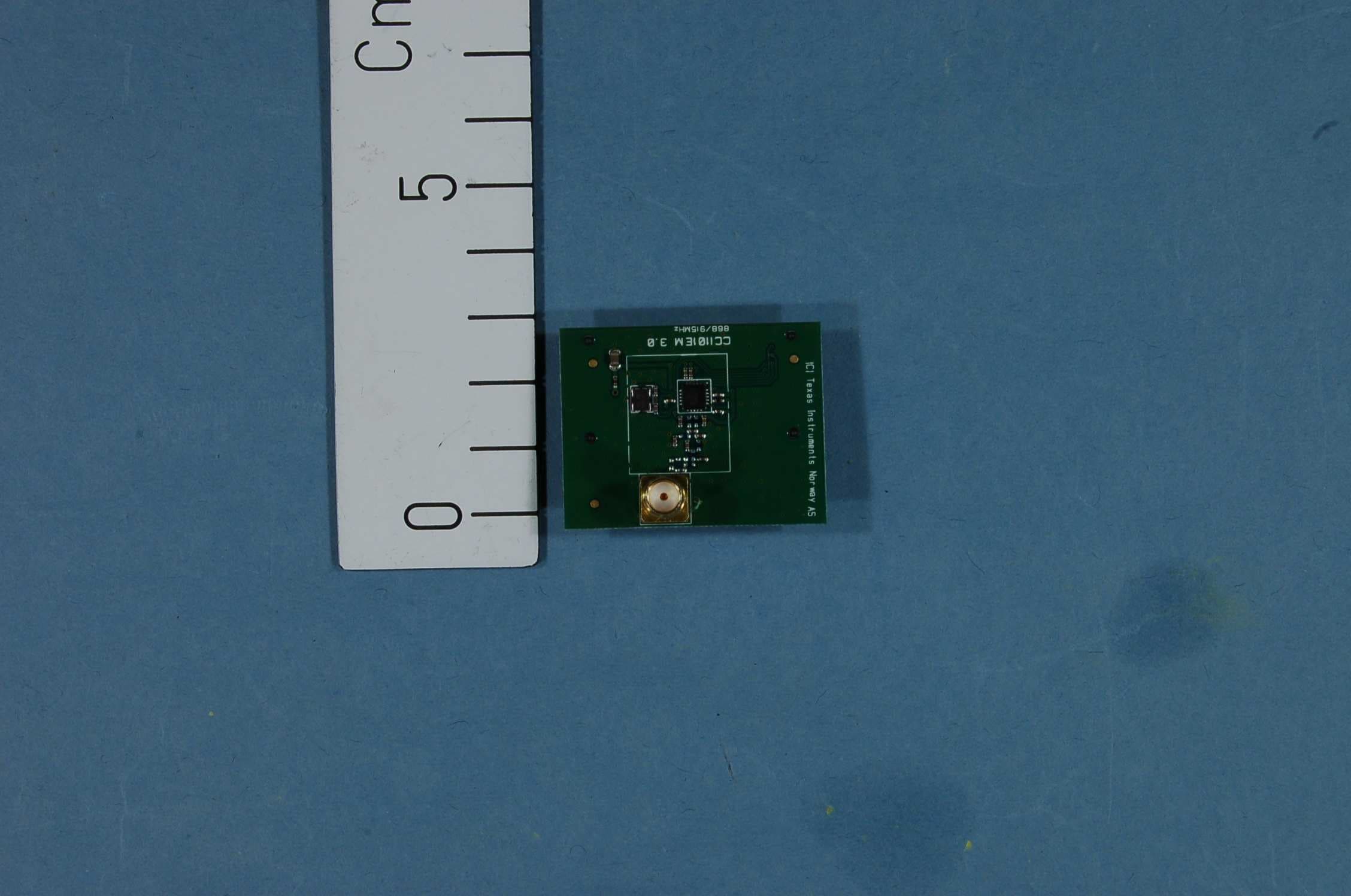
Click to zoom
Application Details
- Equipment Class
- DXT - Part 15 Low Power Transceiver, Rx Verified
- Date of Grant
- Jan 09, 2013
- Application Purpose
- Original Equipment
- Date of Application
- Jan 09, 2013
- Equipment Note
- The CC1101EM-868-915 is a development tool for TIs sub 1 GHz CC1101 chip.
- Frequency Range
- 903.50000000 - 926.50000000
- Company
- Texas Instruments Inc.
- Country
- United States
Documents & Files
Document Text
Text extracted from the exhibit documents filed with the FCC. Open a document above to read the original.
Users Manual
SWRU261A December 2012 CC1101EMK 868/915 MHz Quick Start Guide Opening the box and using the modules with SmartRF04EB 1. Kit Contents 2 x CC1101EM-868-915 2 x W5017 Pulse Antennas The hardware in this kit is FCC/IC certified and complies with ETSI/R&TTE over temperature from 0 to +35°C. The W5017 whip antenna from Pulse has a gain of 2 dBi. 2. How to use the modules The CC1101EM boards can be plugged into several development boards from Texas Instruments. Most notably, you can use SmartRF04EB, which is included in the CC1101DK, or the SmartRF TrxEB (included in CC1120DK). These boards let you run a packet error rate (PER) test, control the device from SmartRF™ Studio and it can be used as a general purpose development platform. The board can also be plugged into the MSP430 Experimenter’s Boards, both the MSP-EXP430F4618 and MSP- EXP430F5438. For prototyping with other microcontrollers, plug the EM into the “SoC Battery Board” (www.ti.com/tool/soc-bb). This guide will show how to use the modules together with SmartRF04EB. 3. Plug EM into SmartRF04EB Insert a CC1101EM (EM) with an antenna into the SmartRF04EB (EB). The connectors will only fit in one position, so that the EM cannot be inserted the wrong way. Caution! The kit contains ESD sensitive components. Handle with care to prevent permanent damage. To minimize risk of injury, avoid touching components during operation if symbolized as hot. 4a. Power: Battery There are three different ways of applying power to the EB: The first method involves using a battery, for instance a 9V battery (not included in the kit) connected to the connector on the bottom side of the board. Warning! To minimize risk of personal injury or property damage, never use rechargeable batteries to power the board. Do not leave the EVM powered when unattended. 4b. Power: DC/External The second method applies DC power (max 10 V, min 4 V, 1500 mA) using the DC input jack (right in picture, centre is +, sleeve is ground), or by connecting a 4 - 10 V voltage source between the 4 - 10 V and 0 V terminals of the power connector (left in picture). It is also possible to connect a 3.3 V voltage source between the 3.3 V and 0 V terminals. The on-board voltage regulators will be bypassed if the 3.3 V input terminal is used. 4c. Power: USB The EB can also be powered from the USB bus. Note that there should only be one active power source at any one time 5. Set Power Switch If a 3.3 V source is used as described in 4b above, the switch should be set to the leftmost position. For all other cases, the switch should be set to the rightmost position. This switch can be used to turn off the EB by switching it to the opposite position of that used to turn it on. 6. Packet Error Rate Test When power is applied to the board, the PER test program will start. You should see the text shown above on the LCD display on both evaluation boards. Press the button marked S1 (lower right corner) to continue. 7. Set Frequency Band Select the desired frequency band of operation by using the joystick. The frequency should match the evaluation module and antenna you are using. Note that the value shown in the display is also the selected value. There is no need to press a button to select or activate the selection. 8. Set Network ID Push the joystick down to display the screen shown above. This lets you set the ID of the node in case you need to run several PER tests simultaneously and you have multiple development kits. Leave this set to 1 for now. 9. Packet Length Push the joystick down to display the screen shown above. This lets you set the length of the packets to be transmitted. The packet length will affect the measured packet error rate. Push the joystick left or right to select the packet length you want to use. 10. Number of Packets Push the joystick down to display the screen shown above. This lets you set the number of packets to be transmitted. Set this to the desired value using the joystick. 11. Select RF Settings Push the joystick down to display the screen shown above. This lets you select preset RF configurations, including modulation and data rate Preset 0: GFSK, 1.2 kBaud Preset 1: GFSK, 10 kBaud Preset 2: GFSK, 38.4 kBaud Preset 3: GFSK, 250 kBaud 12. Select Mode Push the joystick down to display the screen shown above. Use the joystick to select master mode. The EB you have configured now will be the master in the PER test. 13. Configure 2 nd EB Perform steps 3 through 11 on the second EB. Push the joystick down until you get the display shown above. Leave this EB in slave mode. 14. Start PER Push the joystick down on both EBs, and the screen shown above is displayed. Push the joystick right on the slave EB first, and then push the joystick right on the master EB. The PER test will start when the two nodes have successfully connected. Note that the PER test uses 10 dBm as default output power, so the EBs should be placed at least 1m apart to avoid saturation of the receiver. 15. Run PER Test The uppermost line of the LCD will show the PER for packets transmitted from the slave to the master, while the second line will show the PER for packets transmitted from the master to the slave. The PER test will end when the number of packets you selected in step 10 is reached or if 100 consecutive packets are lost. 16. References Please visit www.ti.com and www.ti.com/tool/cc1101emk433 www.ti.com/tool/cc1101emk868-915 Download the CC1101DK User Manual, the SmartRF™ Studio software, examples, as well as datasheets, reference designs and application notes. You will also find a lot of information on the TI E2E forum at http://e2e.ti.com We hope that you will enjoy working with the CC1101 device. SmartRF™ Studio 1. Download and Install Before connecting the EB to your PC, download SmartRF™ Studio from www.ti.com/smartrfstudio. Install the program and follow the instructions in the wizard. Connect the EB with a CC1101EM to the PC using the USB cable and install the USB driver as described in…
Text truncated - open the document above for the full version.
Block Diagram
CC1101EM-868-915 CC1101 f = <902MHz – 928MHz> LNA PA FREQUENCY SYNTHESIZER f_internal = <5412MHz – 5568MHz> f_output = <902MHz – 928MHz> AAF ADC ADC DEMODULATOR MODULATOR RADIO CONTROLLER AND DATA INTERFACE RF_P RF_N X O S C _ Q 2 X O S C _ Q 1 13MHz RC-OSC 34.7kHz RC-OSC 26MHz Crystal OSC IQ Q I BALUN CTRL
External Photos
Project no.: 182234-4 Page 1 of 3 EXTERNAL PHOTOS – CC1101EM- with TrxEB CC1101EM – with TrxEB Project no.: 182234-4 Page 2 of 3 Whip antenna Project no.: 182234-4 Page 3 of 3 PHOTOS OF ACCESSORIES Evaluation board – Front Evaluation board - rear
ID Label/Location Info
Certification Document Label 1/1 Description of label for CC1101EM-868-915 FCC/IC/CE labeling of product is shown below. There is a separate label with the model name, optional variant designator, revision, serial number, FCC ID and IC number. Texas Instruments Model: CC1101EM-868-915 (xx) Rev. x.x.x S.No.: xxxxxx FCC ID: ZAT1101EM900 IC: 451H-1101EM900 ~ 1 3 m m ~ 25 mm Placement of label on product ~39 mm ~ 3 0 m m T e x a s I n s t r u m e n t s M o d e l : C C 1 1 0 1 E M - 8 6 8 - 9 1 5 ( x x ) R e v . x . x . x S . N o . : x x x x x x F C C I D : Z A T 1 1 0 1 E M 9 0 0 I C : 4 5 1 H - 1 1 0 1 E M 9 0 0 Label manufacturer is Brady. Label part number B473 (http://www.bradyid.com/bradyid/domino/contentView.do/B473.html) with print using series R6000 ribbons (R6007 - http://www.bradyid.com/bradyid/pdpv/IP-R6007.html).
Internal Photos
Project no.: 182234-4 Page 1 of 3 EXTERNAL PHOTOS – CC1101EM- with TrxEB CC1101EM – with TrxEB Project no.: 182234-4 Page 2 of 3 Whip antenna Project no.: 182234-4 Page 3 of 3 PHOTOS OF ACCESSORIES Evaluation board – Front Evaluation board - rear
Operational Description
Texas Instruments Norway AS Gaustadalléen 21 0349 Oslo Norway (+47) 22 95 85 44 (+47) 22 95 85 46 Technical Description The CC1101EM-868-915, see Figure 1, includes Texas Instruments’ CC1101, which is a sub-1 GHz transceiver designed for low power wireless applications. CC1101 has a balanced output (RF_N and RF_P), which is transformed to a single ended, 50 ohm signal through a passive component (capacitor/inductor) balun. The output of the balun is low pass filtered to attenuate harmonic radiation and then connected to an SMA connector. The antenna supplied with the board is W5012 from Pulse Electronics. The antenna datasheet is attached for further details. The CC1101EM-868-915 cannot be pre-programmed and CC1101 will not be in active mode (transmit or receive) at power-up. The user needs to configure CC1101 into active mode. Figure 1. CC1101EM-868-915
Operational Description
© 2010. All Rights Reserved. External Outdoor Antenna for 900MHz Application Pulse Part Number: W5012 Pulse North Asia 3F, No. 198, Zhongyuan Rd Zhongli City (32068) Taoyuan Hsien Taiwan (R.O.C.) TEL: 886 3 4356768 FAX: 886 3 4356823 Asian Headquarters B402, Shenzhen Academy of Aerospace Tech Bldg Tech-Innovation Internat’l 10th Kejinan Rd High-Tech Zone Nanshan District, Shenzen PR China TEL: 86 755 33966678 FAX: 86 755 33966700 Pulse (Suzhou) Wireless Products Co, Ltd #99 Huo Ju Rd (# 29 Bldg, 4th phase) Suzhou New District Science & Technology Industrial Park Jiangsu Province Suzhou 215009, PR China TEL: 86 512 6807 9998 FAX: 86 512 6809 8023 European Headquarters & Automotive Headquarters Pulse GmbH & Co. KG Zeppelinstrasse 15 Germany TEL: +49 7032 7806 0 FAX: +49 7032 7806 12 Worldwide Headquarters 12220 World Trade Drive San Diego, CA 92128 USA Map from San Diego Airport TEL: 858 674 8100 FAX: 858 674 8262 Antennas Larsen Brand 3611 NE 112th Ave Vancouver, WA 98682 United States TEL: 800 ANTENNA (USA) 800 268-3662 FAX: 800 525 6749 Features - Antenna size: ø10x179mm - Ingress Protection IP65 - UV protection - RoHS Compliant Product Applications - ISM 900MHz - Metering, Security, M2M Applications Part Numbers: Electrical specifications @ +25 °C Typical free space performance Frequency Range [MHz] Max Gain [dBi] Efficiency [%] Return loss min. [dB] Impedance [Ω] Operating Temperature [°C] 868-9282.060-8.050-40 to +85 P/NConnector W5012 Straight RP-SMA (Male Body, Female Pin) 179 ± 1 92,3±0,3 10±0,2 © 2010. All Rights Reserved. External Outdoor Antenna for 900MHz Application Pulse Part Number: W5012 Pulse North Asia 3F, No. 198, Zhongyuan Rd Zhongli City (32068) Taoyuan Hsien Taiwan (R.O.C.) TEL: 886 3 4356768 FAX: 886 3 4356823 Asian Headquarters B402, Shenzhen Academy of Aerospace Tech Bldg Tech-Innovation Internat’l 10th Kejinan Rd High-Tech Zone Nanshan District, Shenzen PR China TEL: 86 755 33966678 FAX: 86 755 33966700 Pulse (Suzhou) Wireless Products Co, Ltd #99 Huo Ju Rd (# 29 Bldg, 4th phase) Suzhou New District Science & Technology Industrial Park Jiangsu Province Suzhou 215009, PR China TEL: 86 512 6807 9998 FAX: 86 512 6809 8023 European Headquarters & Automotive Headquarters Pulse GmbH & Co. KG Zeppelinstrasse 15 Germany TEL: +49 7032 7806 0 FAX: +49 7032 7806 12 Worldwide Headquarters 12220 World Trade Drive San Diego, CA 92128 USA Map from San Diego Airport TEL: 858 674 8100 FAX: 858 674 8262 Antennas Larsen Brand 3611 NE 112th Ave Vancouver, WA 98682 United States TEL: 800 ANTENNA (USA) 800 268-3662 FAX: 800 525 6749 Linear Max Gain [dBi] Freq [MHz] Max Gain Max Gain 4 3 2 1 0 -1 -2 868 873 878 883 888 893 898 903 908 913 918 923 928 START 2140.000 000 MHzSTOP 2740.000 000 MHz CH1Markers 1. -9.1441 dB 868.00000 MHz 2. -8.9639 dB 928.00000 MHz Typical Return Loss 5 dB/REF 0 dBTr1 S11 Log Mag 1 2 START 2140.000 000 MHzSTOP 2740.000 000 MHz CH1Markers 1. 2.0936 868.00000 MHz 2. 2.0636 928.00000 MHz VSWR 1.000/REF 1.000Tr1 S11 SWR 1 2 © 2010. All Rights Reserved. External Outdoor Antenna for 900MHz Application Pulse Part Number: W5012 Pulse North Asia 3F, No. 198, Zhongyuan Rd Zhongli City (32068) Taoyuan Hsien Taiwan (R.O.C.) TEL: 886 3 4356768 FAX: 886 3 4356823 Asian Headquarters B402, Shenzhen Academy of Aerospace Tech Bldg Tech-Innovation Internat’l 10th Kejinan Rd High-Tech Zone Nanshan District, Shenzen PR China TEL: 86 755 33966678 FAX: 86 755 33966700 Pulse (Suzhou) Wireless Products Co, Ltd #99 Huo Ju Rd (# 29 Bldg, 4th phase) Suzhou New District Science & Technology Industrial Park Jiangsu Province Suzhou 215009, PR China TEL: 86 512 6807 9998 FAX: 86 512 6809 8023 European Headquarters & Automotive Headquarters Pulse GmbH & Co. KG Zeppelinstrasse 15 Germany TEL: +49 7032 7806 0 FAX: +49 7032 7806 12 Worldwide Headquarters 12220 World Trade Drive San Diego, CA 92128 USA Map from San Diego Airport TEL: 858 674 8100 FAX: 858 674 8262 Antennas Larsen Brand 3611 NE 112th Ave Vancouver, WA 98682 United States TEL: 800 ANTENNA (USA) 800 268-3662 FAX: 800 525 6749 Typical Free Space Radiation Patterns Horizonal Plane Vertical Plane -25 -25 -20 -20 -15 -15 -10 -10 -5 -5 0 0 5 5 0 30 60 90 12 0 15 0 18 0 21 0 24 0 27 0 30 0 33 0 0 30 60 90 12 0 15 0 18 0 21 0 24 0 27 0 30 0 33 0
Parts List/Tune Up Info
CC1101EM-868-915 Partlist Ref. Part name Pcs/unit Description Manufacturer Part number U1 CC1101 1 Single-chip transceiver TI CC1101 C41;C51;C91;C111;C141;C151;C181 C_100N_0402_X5R_K_10 7 Capacitor, 100n, 0402, X5R, 10%, 10V Murata GRM155R71A104KA01D C124 C_100P_0402_NP0_J_50 1 Capacitor, 100p, 0402, NP0, 5% 50V Murata GRM1555C1H101JZ01D C81;C125 C_12P_0402_NP0_J_50 2 Capacitor, 12p, 0402, NP0, 5%, 50V Murata GRM1555C1H120JZ01D C101 C_15P_0402_NP0_J_50 1 Capacitor, 15p, 0402, NP0, 5%, 50V Murata GRM1555C1H150JZ01D C121 C_1P0_0402_NP0_C_50 1 Capacitor, 1p, 0402, NP0, +/-0.25pF 50V Murata GRM1555C1H1R0CZ01D C122;C131 C_1P5_0402_NP0_C_50 2 Capacitor, 1p5, 0402, NP0, +-0.25pF, 50V Murata GRM1555C1H1R5CZ01D C1 C_1U_0805_X7R_K_16 1 Capacitor, 1u, 0805, X7R, 10%, 16V Murata GRM21BR71C105KA01L C123 C_3P3_0402_NP0_C_50 1 Capacitor, 3p3, 0402, NP0, +-0.25pF, 50V Murata GRM1555C1H3R3CZ01D C126 Do not mount 0 L121;L123-124;L131 L_12N_0402_J_LQW 4 Inductor, 12n, 0402, ±5%, wire-wound type Murata LQW15AN12NJ00D L122;L132 L_18N_0402_J_LQW 2 Inductor, 18n, 0402, ±5%, wire-wound type Murata LQW15AN18NJ00D L125 Do not mount 0 #N/A L1 L_BEAD_102_0402 1 EMI filter bead, 0402 1Kohms Tape GHz Band Gen Use Murata BLM15HG102SN1D R171 R_56K_0402_F 1 Resistor, 56k ohms, 0402, ±1% Koa RK73H1ETTP5602F P3 SMA_SMD 1 P1-2 SMD_SOCKET_2x10 2 SMD pinrow socket, .050 spacing, 2x10 Samtec SFM-110-02-SM-D-A-K- TR X1 X_26.000/20/40/40/10 1 Crystal, 26.000000MHz, 10.0pF, 50 ohms max, 20/40 ppm, -40C to +85C NDK NX3225GA, EXS00A- CG01972
Test Report
Nemko AS, Gaustadalléen 30, P.O.Box 73 Blindern, NO-0314 Oslo Norway T +47 22 96 03 30 F +47 22 96 05 50 Enterprise number NO974404532 Visiting address: Nemko Kjeller, Instituttveien 6, P.O.Box 96, NO-2027 Kjeller Norway T +47 64 84 57 00 F +47 64 84 57 05 Test report no. : 182234-4 Item tested : CC1101EM-868-915 Type of equipment : Low Power Transceiver FCC ID : ZAT1101EM900 Client : Texas Instruments Norway AS FCC Part 15.249 Low Power Transceiver 902-928 MHz Band RSS-210, Issue 8 and RSS-GEN, Issue 3 Low-Power Licence-exempt Radiocommunications devices 902 – 928 MHz Band 13 December 2012 Authorized by : .............................................. Frode Sveinsen Technical Verificator TEST REPORT FCC part 15.249 Project no.: 182241-4 FCC ID: ZAT1101EM900 Nemko AS, NO-2027 Kjeller Page 2 (37) CONTENTS 1 GENERAL INFORMATION ...................................................................................................... 3 1.1 Testhouse Info .......................................................................................................................... 3 1.2 Client Information ...................................................................................................................... 3 1.3 Manufacturer ............................................................................................................................. 3 2 Test Information ...................................................................................................................... 4 2.1 Test Item ................................................................................................................................... 4 2.2 Test Environment ...................................................................................................................... 5 2.3 Test Period................................................................................................................................ 5 3 TEST REPORT SUMMARY ..................................................................................................... 6 3.1 General ..................................................................................................................................... 6 3.2 Test Summary ........................................................................................................................... 7 3.3 Description of modification for Modification Filing ..................................................................... 7 3.4 Comments ................................................................................................................................ 7 3.5 Family List Rationale ................................................................................................................ 7 4 TEST RESULTS ....................................................................................................................... 8 4.1 Transmitter Frequency Stability ................................................................................................ 8 4.2 20 dB Bandwidth ....................................................................................................................... 9 4.3 Peak Power Output ................................................................................................................. 11 4.4 Band Edge Emissions ............................................................................................................. 21 4.5 Spurious Emissions (Radiated) .............................................................................................. 24 4.6 Receiver Spurious Emissions (Radiated) ............................................................................... 33 5 LIST OF TEST EQUIPMENT .................................................................................................. 35 6 BLOCK DIAGRAM ................................................................................................................. 36 6.1 System set up for radiated measurements ............................................................................. 36 6.2 Power line Conducted Emission ............................................................................................. 36 6.3 Test Site Radiated Emission ................................................................................................... 37 TEST REPORT FCC part 15.249 Project no.: 182241-4 FCC ID: ZAT1101EM900 Nemko AS, NO-2027 Kjeller Page 3 (37) 1 GENERAL INFORMATION 1.1 Testhouse Info Name : Nemko AS Address : Nemko Kjeller Instituttveien 6, Box 96 NO-2027 Kjeller, NORWAY Telephone : +47 64 84 57 00 Fax : +47 64 84 57 05 Email: [email protected] FCC test firm : 994405 IC OATS : 2040D-1 Total Number of Pages: 37 1.2 Client Information Name : Texas Instruments Norway AS Address : Gaustadallen 21, NO-0349 Oslo, Norway Telephone : +47 22 95 85 44 Fax : +47 22 95 85 46 Contact: Name : Dag Grini Telephone : +47 22 95 83 01 E-mail : [email protected] 1.3 Manufacturer Same as client. TEST REPORT FCC part 15.249 Project no.: 182241-4 FCC ID: ZAT1101EM900 Nemko AS, NO-2027 Kjeller Page 4 (37) 2 Test Information 2.1 Test Item Name : CC1101EM with TrxEB Model/version : CC1101EM-868-915 FCC ID : ZAT1101EM900 IC : 451H-1101EM900 Serial number : - Hardware identity and/or version: - Software identity and/or version : - Frequency Range : 903.5 – 926.5 MHz Operating Frequency: 903.5, 915, 926.5MHz Operating Modes : TX & RX Type of Modulation : 2-GFSK Data rate: 1.2kbit/s Conducted Output Power : 0.00057 mW (Peak) Type of Power Supply : 3.0V dc* Antenna Connector : SMA connector Antenna type: Whip -1/4 wave Antenna Diversity Supported : None *Tested with battery pack (2xAA Primary batteries). Theory of Operation The CC1101EM-868-915 RF-transceiver is a development tool for the CC1101 chip. TEST REPORT FCC part 15.249 Project no.: 182241-4 FCC ID: ZAT1101EM900 Nemko AS, NO-2027 Kjeller Page 5 (37) 2.2 Test Environment 2.2.1 Normal test condition Tem…
Text truncated - open the document above for the full version.
Test Setup Photos
Project no.: 182234-4 Page 1 of 1 PHOTOS OF TEST SET-UP Radiated emissions 30 - 1000MHz Radiated Emissions Test – 1 - 10GHz
Contact Information
Applicant
Marian Kost(Product Line Manager, Connectivity)
Technical Contact
Texas instruments Norway ASSiri Johnsrud
[email protected]+4722958537
Gaustadall�en 21 · Oslo · Norway
Non-Technical Contact
Nemko USA, Inc.Zarah G. MacIvor
[email protected]214-629-5683
Test Firm
Nemko ASFrode Sveinsen
Technical Specifications
| # | Rule Parts | Frequency Range | Power Output |
|---|---|---|---|
| 1 | 15C | 903.5 MHz - 926.5 MHz | - |
Other Applications from Texas Instruments Inc.
ZAT-2340R5MODA
Jan 30, 2026CC2340R5MODAN0MHAR
Equipment Class
DTS - Digital Transmission SystemZAT-1312PSIP-3
May 19, 2024CC1312PSIP
Equipment Class
DSS - Part 15 Spread Spectrum TransmitterZAT-1312PSIP-2
Jan 21, 2024CC1312PSIP
Equipment Class
DSS - Part 15 Spread Spectrum Transmitter
ZAT-1312PSIP-1
Jul 09, 2023CC1312PSIP
Equipment Class
DSS - Part 15 Spread Spectrum Transmitter
ZAT7IDEM
Feb 27, 2014The 7IDEM is a development tool for TIs 2.4 GHz 7ID System-on-Chip
Equipment Class
DTS - Digital Transmission System