ZAT1111USB900The CC1111Dongle-868 is a development tool for TIs sub 1 GHz CC1111 chip
Texas Instruments Inc.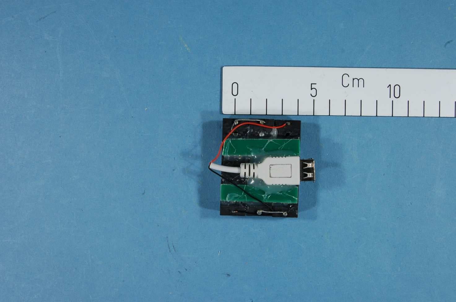
Click to zoom
Application Details
- Equipment Class
- DXT - Part 15 Low Power Transceiver, Rx Verified
- Date of Grant
- Jan 08, 2013
- Application Purpose
- Original Equipment
- Date of Application
- Jan 08, 2013
- Equipment Note
- The CC1111Dongle-868 is a development tool for TIs sub 1 GHz CC1111 chip
- Frequency Range
- 903.50000000 - 926.50000000
- Company
- Texas Instruments Inc.
- Country
- United States
Documents & Files
Document Text
Text extracted from the exhibit documents filed with the FCC. Open a document above to read the original.
Users Manual
SWRU328 December 2012 CC1111 USB Evaluation Kit 868/915 MHz Quick Start Guide 1. Kit Contents 1 x CC1111 USB Dongle (CC1111Dongle-868) This Quick Start Guide The hardware in this kit is FCC and IC certified and complies with ETSI/R&TTE requirements over temperature from 0 to +35°C. 2. Getting Started The CC1111 USB Dongle can be used as a development platform for USB and RF applications. An external development board or debugger, like the CC Debugger, SmartRF04EB or SmartRF05EB, is required to program and debug software running on the CC1111. Note that the CC1111 USB Dongle is pre-programmed with the packet sniffer firmware. This Quick Start Guide will describe how to use the dongle with the packet sniffer and what would be the next steps for developing your own software. 3. Preparations Before proceeding, please download and install the following tools: SmartRF Flash Programmer www.ti.com/tool/flash-programmer You will need this tool to program the packet capture firmware on the CC1111 USB dongle SmartRF Packet Sniffer www.ti.com/packetsniffer This is the PC tool that displays and parses the packets received by the capture device. 4. Programming the Dongle For the USB dongle to operate as a packet capture device, it must be programmed with the packet sniffer firmware. By default, the dongle comes pre-programmed with this firmware. Connect the USB dongle to the debugger or the development board with an appropriate 10 pin flat cable. The dongle must also be powered via the USB bus. Refer to picture below for an example. Caution! Avoid using other power sources for the dongle than a regular USB voltage source at max 5.5V, 500 mA. 5. Programming the Dongle Launch the SmartRF Flash Programmer and make sure you select the “System-on-Chip” tab. The tool should show a line with CC1111 connected to a SmartRF04EB. Next, locate the flash image sniffer_fw_ccxx11.hex in “C:\Program Files\Texas Instruments\SmartRF Tools\Packet Sniffer\bin\general\firmware” Select “Erase, program and verify” and press the “Perform Actions” button. 6. Install USB Driver After programming the device, disconnect the dongle from the programming board and plug it into the PC. Windows’ new hardware wizard will appear. Select the options for automatic installation and wait for the driver installation to complete. If the Wizard asks for a specific driver, point it to the cebal2.inf file located in “C:\Program Files\Texas Instruments\SmartRF Tools\Drivers\cebal\win_<arch-specific>\” After installation of the driver, the Packet Sniffer capture device is ready for use. Web sites: www.ti.com/lprf E2E Forum: www.ti.com/lprf-forum Make sure to subscribe to the Low-Power RF Newsletter to receive information about updates to documentation, new product releases, and more. Sign up on the TI web pages. 7. Packet Sniffer (1) Launch the Packet Sniffer. A dialog will request the user to select a protocol. The CC1111 capture device can be used with the SimpliciTI or the Generic (no parsing) protocols. A new window will appear. The USB dongle should be listed with chip type CC1111 and EB type CC1111 USB dongle in the “Capturing Device” tab. Highlight the device to make it your capture device. 8. Packet Sniffer (2) Next, select the Radio Configuration tab and make sure the radio registers on the device are set according to the format of the radio signals you are sniffing. If this is the first time you use the tool, press the browse button to locate a .prs file with packet sniffer register settings for CC1111. You can generate your own .prs files with the “Register Export” function in SmartRF Studio 9. Packet Sniffer (3) Finally, press the small “play” icon on the tool bar to start sniffing packets. If there are radio packets on the air, and the CC1111 has the appropriate radio settings, the captured packets will be displayed in the packet sniffer display window. Enjoy! 10. Developing USB Software A good start for developing your own USB application for the CC1111 USB dongle would be the “CC USB Firmware Library and Examples” software package. The Library contains a complete USB framework that allows the user to develop any USB device type. Examples showing implementations of a HID device and a CDC device are included. The software can be downloaded from the CC1111EMK web page or directly from www.ti.com/lit/zip/swrc088 11. Development Tools The preferred tool for developing software for CC1111 and for single stepping and debugging is IAR Embedded Workbench for 8051. A free, code size limited version can be downloaded from the web. See www.iar.com/ew8051 12. Thank You! We hope you will enjoy working with the CC1111 device and related Low-Power RF products from Texas Instruments. The Low Power RF Online Community has forums, blogs and videos. Use the forums to find information, discuss and get help with your design. Join us at www.ti.com/lprf-forum Caution! The kit contains ESD sensitive components. Handle with care to prevent permanent damage. To minimize risk of injury, avoid touching components during operation if symbolized as hot. EVALUATION BOARD/KIT/MODULE (EVM) ADDITIONAL TERMS Texas Instruments (TI) provides the enclosed Evaluation Board/Kit/Module (EVM) under the following conditions: The user assumes all responsibility and liability for proper and safe handling of the goods. Further, the user indemnifies TI from all claims arising from the handling or use of the goods. Should this evaluation board/kit not meet the specifications indicated in the User’s Guide, the board/kit may be returned within 30 days from the date of delivery for a full refund. THE FOREGOING LIMITED WARRANTY IS THE EXCLUSIVE WARRANTY MADE BY SELLER TO BUYER AND IS IN LIEU OF ALL OTHER WARRANTIES, EXPRESSED, IMPLIED, OR STATUTORY, INCLUDING ANY WARRANTY OF MERCHANTABILITY OR FITNESS FOR ANY PARTICULAR PURPOSE. EXCEPT TO THE EXTENT OF THE INDEMNITY SET FORTH ABOVE, NEITHER PARTY SHALL BE LIABLE TO THE OTHER FOR ANY INDIRECT, SPECIAL, INCIDENTAL, OR CONSEQUENTIAL…
Text truncated - open the document above for the full version.
Block Diagram
f = <902MHz – 928MHz> LNA PA FREQUENCY SYNTHESIZER f_internal = <5412MHz – 5568MHz> f_output = <902MHz – 928MHz> AAF ADCADC DEMODULATOR MODULATOR RADIO CONTROLLER AND DATA INTERFACE RF_P RF_N CLOCK MUX XOSC_Q2 XOSC_Q1 12MHz RC-OSC 32kHz RC-OSC 48MHz Crystal OSC IQ Q I BALUN DMARAM CPU CTRL USB DP DM Divide-by-2
External Photos
Project no.: 182223-5 Page 1 of 2 EXTERNAL PHOTOS – CC1111Dongle CC1111 – USB Dongle Project no.: 182223-5 Page 2 of 2 PHOTOS OF ACCESSORIES USB battery jig
ID Label/Location Info
Certification Document Label 1/1 Description of label for CC1111Dongle-868 FCC/IC/CE labeling of product is shown below. There is a separate label with the model name, optional variant designator, revision, serial number, FCC ID and IC number. Texas Instruments Model: CC1111Dongle-868 (xx) Rev. x.x.x S.No.: xxxxxx FCC ID: ZAT1111USB900 IC: 451H-1111USB900 ~ 1 3 m m ~ 25 mm Placement of label on product ~22 mm ~ 4 0 m m 1 5 m m 11 mm T e x a s I n s t r u m e n t s M o d e l : C C 1 1 1 1 D o n g l e - 8 6 8 ( x x ) R e v . x . x . x S . N o . : x x x x x x F C C I D : Z A T 1 1 1 1 U S B 9 0 0 I C : 4 5 1 H - 1 1 1 1 U S B 9 0 0 Label manufacturer is Brady. Label part number B473 (http://www.bradyid.com/bradyid/domino/contentView.do/B473.html) with print using series R6000 ribbons (R6007 - http://www.bradyid.com/bradyid/pdpv/IP-R6007.html).
Internal Photos
Project no.: 182223-5 Page 1 of 2 EXTERNAL PHOTOS – CC1111Dongle CC1111 – USB Dongle Project no.: 182223-5 Page 2 of 2 PHOTOS OF ACCESSORIES USB battery jig
Operational Description
Texas Instruments Norway AS Gaustadalléen 21 0349 Oslo Norway (+47) 22 95 85 44 (+47) 22 95 85 46 Technical Description The CC1111Dongle-868, see Figure 1, includes Texas Instruments’ CC1111, which is a sub- 1 GHz system-on-chip (SoC) designed for low power wireless applications. The CC1111 combines a sub-1 GHz transceiver and a single-cycle 8051 MCU, 32 kB of in-system programmable flash memory, 4 kB of RAM, and a full-speed USB 2.0 interface. CC1111 has a balanced output (RF_N and RF_P), which is transformed to a single ended, 50 ohm signal through a passive component (capacitor/inductor) balun. The output of the balun is low pass filtered to attenuate harmonic radiation and then connected to a 0868AT43A002 Johanson Technology chip antenna with a PCB track added for tuning of the resonance frequency. For antenna performance please refer to design note DN016 (www.ti.com/lit/swra160). The CC1111Dongle-868 is not pre-programmed and CC1111 will not be in active mode (transmit or receive) at power-up. An external ICE is needed for initial programming of the CC1111. Figure 1 CC1111Dongle-868
Parts List/Tune Up Info
Ref. Part name Pcs/unit Description Manufacturer Part number U1 CC1111 1 Single-chip transceiver with 8051 MCU and USB TI CC1111 C6;C236 C_0402 2 Capacitor, general, 0402; Do not mount C121;C291 C_100N_0402_X5R_K_10 2 Capacitor, 100n, 0402, X5R, 10%, 10V Murata GRM155R71A104KA01D C232;C235 C_100P_0402_NP0_J_50 2 Capacitor, 100p, 0402, NP0, 5% 50V Murata GRM1555C1H101JZ01D C191;C251 C_10N_0402_X7R_K_25 2 Capacitor, 10n, 0402, X7R, 10%, 25V Murata GRM155R71E103KA01D C231 C_1P0_0402_NP0_C_50 1 Capacitor, 1p, 0402, NP0, +/-0.25pF 50V Murata GRM1555C1H1R0CZ01D C233;C241 C_1P5_0402_NP0_C_50 2 Capacitor, 1p5, 0402, NP0, +-0.25pF, 50V Murata GRM1555C1H1R5CZ01D C301 C_1U_0402_X5R_K_6P3 1 Capacitor, 1u, 0402, X5R, 10%, 6.3V Murata GRM155R60J105KE19D C1 C_1U_0603_X5R_L_6P3 1 Capacitor, 1u, 0603, X5R, 15%, 6.3V Murata GRM188R60J105KA01D C261 C_220P_0402_NP0_J_50 1 Capacitor, 220p, 0402, NP0, 5%, 50V Murata GRM1555C1H221JA01D C221 C_2P2_0402_NP0_C_50 1 Capacitor, 2p2, 0402, NP0, +-0.25pF, 50V Murata GRM1555C1H2R2CZ01 C5 C_2U2_0805_X5R_K_10 1 Capacitor, 2u2, 0805, X5R, 10%, 10V Murata GRM219R61A225KA01D C203;C214 C_22P_0402_NP0_J_50 2 Capacitor, 22p, 0402, NP0, 5%, 50V Murata GRM1555C1H220JZ01D C234 C_3P3_0402_NP0_C_50 1 Capacitor, 3p3, 0402, NP0, +-0.25pF, 50V Murata GRM1555C1H3R3CZ01D C3-4 C_47P_0402_NP0_J_50 2 Capacitor, 47p, 0402, NP0, 5%, 50V Murata GRM1555C1H470JZ01D C2 C_4U7_0603_X5R_K_6 1 Capacitor, 4u7, 0603, X5R, 10%, 6.3V Murata GRM188R60J475KE19D A1 Johanson_868_MHz_Chip_Antenna 1 Johanson 868 MHz chip antenna Johanson Technology 0868AT43A0020 D2 LED_EL19-21SYGC 1 LED, green, 0603, 2.0V, 16mcd Everlight 19-21SYGC/S530-E1/TR8 L231;L233-235;L241 L_12N_0402_J 5 Inductor, 12n, 0402, ±5% Murata LQG15HS12NJ02D L232;L242 L_18N_0402_J 2 Inductor, 18n, 0402, ±5% Murata LQG15HS18NJ02D L236 L_1N8_0402_S 1 Inductor, 1n8, 0402, Monolithic type, +/-0.3 nH Murata LQG15HS1N8S02D L1 L_BEAD_102_0402 1 EMI filter bead, 0402 1Kohms Tape GHz Band Gen Use Murata BLM15HG102SN1D P3-4 PINROW_2X5 2 2x5 pinrow, 2.54mm pitch, through-hole CEN Link (Taiwain) YPH-D-ST-10-G S1 PUSH_BUTTON_SKRK 1 Momentary push-button, SMD 3.9*2.9*2 mm Alps SKRKAEE010 R3;R6-7 R_0402 3 Resistor, general, 0402; Do not mount R5;R8 R_0_0402 2 Resistor, 0 ohm, 0402 Koa RK73Z1ETTP R264 R_1K5_0402_G 1 Resistor, 1k5 ohms, 0402, 2% Koa RK73H1ETTP1501F (±1%) R1 R_270_0402_F 1 Resistor, 270 ohms, 0402, ±1% Koa RK73H1E270RF-MR or RK 7 R2 R_2_0402_F 1 Resistor, 2 ohms, 0402, ±1% Koa RK73H1ETTP2R00F R262-263 R_33_0402_G 2 Resistor, 33 ohms, 0402, 2% Koa RK73H1ETTP33R0F (±1%) R4 R_4K7_0402_G 1 Resistor, 4k7 ohms, 0402, 2% Koa RK73H1ETTP4701F (±1%) R271 R_56K_0402_F 1 Resistor, 56k ohms, 0402, ±1% Koa RK73H1ETTP5602F P5 - DO NOT MOUN T SMD_HEADER_2x5 0 SMD pinrow header, .050 spacing, 2x5 without alignmen t Samtec TFM-105-02-SM-D-K-TR U2 TPS76933 1 ULTRALOW-POWER 100-mA LOW-DROPOUT LINEAR TI TPS76933DBVR or -T P1 USB_A 1 USB Plugg A/PCB Montering ELFA 42-197-15 X2 X_48.000/20/35/20/18 1 Crystal, ceramic SMD, 4x2.5mm, +/-20ppm 48MHZ Abracon ABM8-48.000MHz-B2-T
Test Report
Nemko AS, Gaustadalléen 30, P.O.Box 73 Blindern, NO-0314 Oslo Norway T +47 22 96 03 30 F +47 22 96 05 50 Enterprise number NO974404532 Visiting address: Nemko Kjeller, Instituttveien 6, P.O.Box 96, NO-2027 Kjeller Norway T +47 64 84 57 00 F +47 64 84 57 05 Test report no. : 182223-5 Item tested : CC1111Dongle-868 Type of equipment : Low power Transceiver 903.5 – 926.5 MHz FCC ID : ZAT1111USB900 Client : Texas Instruments Norway AS FCC Part 15.249 Low Power Transceiver 902-928 MHz Band RSS-210, Issue 8 and RSS-GEN, Issue 3 Low-Power Licence-exempt Radiocommunications devices 902 – 928 MHz Band 6 December 2012 Authorized by : .............................................. Frode Sveinsen Technical Verificator TEST REPORT FCC part 15.249 Project no.: 182223-5 FCC ID: ZAT1111USB900 Nemko AS, NO-2027 Kjeller Page 2 (48) CONTENTS 1 GENERAL INFORMATION ...................................................................................................... 3 1.1 Testhouse Info .......................................................................................................................... 3 1.2 Client Information ...................................................................................................................... 3 1.3 Manufacturer ............................................................................................................................. 3 2 Test Information ...................................................................................................................... 4 2.1 Test Item ................................................................................................................................... 4 2.2 Test Environment ...................................................................................................................... 5 2.2.1 Normal test condition ................................................................................................... 5 2.3 Test Period................................................................................................................................ 5 3 TEST REPORT SUMMARY ..................................................................................................... 6 3.1 General ..................................................................................................................................... 6 3.2 Test Summary ........................................................................................................................... 7 3.3 Description of modification for Modification Filing ..................................................................... 7 3.4 Comments ................................................................................................................................ 7 3.5 Family List Rationale ................................................................................................................ 7 4 TEST RESULTS ....................................................................................................................... 8 4.1 Power-line Conducted Emissions ............................................................................................. 8 4.2 Transmitter Frequency Stability .............................................................................................. 11 4.3 20 dB Bandwidth ..................................................................................................................... 12 4.4 Peak Power Output ................................................................................................................. 16 4.5 Band Edge Emissions ............................................................................................................. 26 4.6 Spurious Emissions (Radiated) .............................................................................................. 29 4.7 Receiver Spurious Emissions (Radiated) ............................................................................... 42 5 LIST OF TEST EQUIPMENT .................................................................................................. 46 6 BLOCK DIAGRAM ................................................................................................................. 47 6.1 System set up for radiated measurements ............................................................................. 47 6.2 Power line Conducted Emission ............................................................................................. 47 6.3 Test Site Radiated Emission ................................................................................................... 48 TEST REPORT FCC part 15.249 Project no.: 182223-5 FCC ID: ZAT1111USB900 Nemko AS, NO-2027 Kjeller Page 3 (48) 1 GENERAL INFORMATION 1.1 Testhouse Info Name : Nemko AS Address : Nemko Kjeller Instituttveien 6, Box 96 NO-2027 Kjeller, NORWAY Telephone : +47 64 84 57 00 Fax : +47 64 84 57 05 Email: [email protected] FCC test firm : 994405 IC OATS : 2040D-1 Total Number of Pages: 48 1.2 Client Information Name : Texas Instruments Norway AS Address : Gaustadallen 21, NO-0349 Oslo, Norway Telephone : +47 22 95 85 44 Fax : +47 22 95 85 46 Contact: Name : Dag Grini Telephone : +47 22 95 83 01 E-mail : [email protected] 1.3 Manufacturer Same as client. TEST REPORT FCC part 15.249 Project no.: 182223-5 FCC ID: ZAT1111USB900 Nemko AS, NO-2027 Kjeller Page 4 (48) 2 Test Information 2.1 Test Item Name : USB Dongle Model/version : CC1111Dongle-868 FCC ID : ZAT1111USB900 IC : 451H-1111USB900 Serial number : 0000 093D Hardware identity and/or version: - Software identity and/or version : - Frequency Range : 903.5 – 926.5 MHz Operating Frequency: 903.5MHz,915MHz,926.5MHz Number of Channels : 1 Operating Modes : TX & RX Type of Modulation : 2-GFSK Data rate: 1.2kbit/s User Frequency Adjustment : None, Software controlled Output Power : 0.36 mW (Peak, Conducted) Type of Power Supply : USB power (tested with 4.5 V DC, 3x 1.5Vdc)* Antenna Connec…
Text truncated - open the document above for the full version.
Test Setup Photos
Project no.: 182223-5 Page 1 of 2 PHOTOS OF TEST SET-UP Radiated emissions 30 - 1000MHz Radiated Emissions Test – 1 - 10GHz Project no.: 182223-5 Page 2 of 2 Power line Conducted Emissions Test
Contact Information
Applicant
Marian Kost(Product Line Manager, Connectivity)
Technical Contact
Texas instruments Norway ASSverre Hellan
[email protected]+4722958905
Gaustadalleen 21 · Oslo · Norway
Non-Technical Contact
Nemko USA, Inc.Zarah G. MacIvor
[email protected]214-629-5683
Test Firm
Nemko ASFrode Sveinsen
Technical Specifications
| # | Rule Parts | Frequency Range | Power Output |
|---|---|---|---|
| 1 | 15C | 903.5 MHz - 926.5 MHz | - |
Other Applications from Texas Instruments Inc.
ZAT-2340R5MODA
Jan 30, 2026CC2340R5MODAN0MHAR
Equipment Class
DTS - Digital Transmission SystemZAT-1312PSIP-3
May 19, 2024CC1312PSIP
Equipment Class
DSS - Part 15 Spread Spectrum TransmitterZAT-1312PSIP-2
Jan 21, 2024CC1312PSIP
Equipment Class
DSS - Part 15 Spread Spectrum Transmitter
ZAT-1312PSIP-1
Jul 09, 2023CC1312PSIP
Equipment Class
DSS - Part 15 Spread Spectrum Transmitter
ZAT7IDEM
Feb 27, 2014The 7IDEM is a development tool for TIs 2.4 GHz 7ID System-on-Chip
Equipment Class
DTS - Digital Transmission System