ZAT1175EM900The CC1175EM-868-915 is a development tool for Texas Instruments sub-1 GHz CC1175 chip.
Texas Instruments Inc.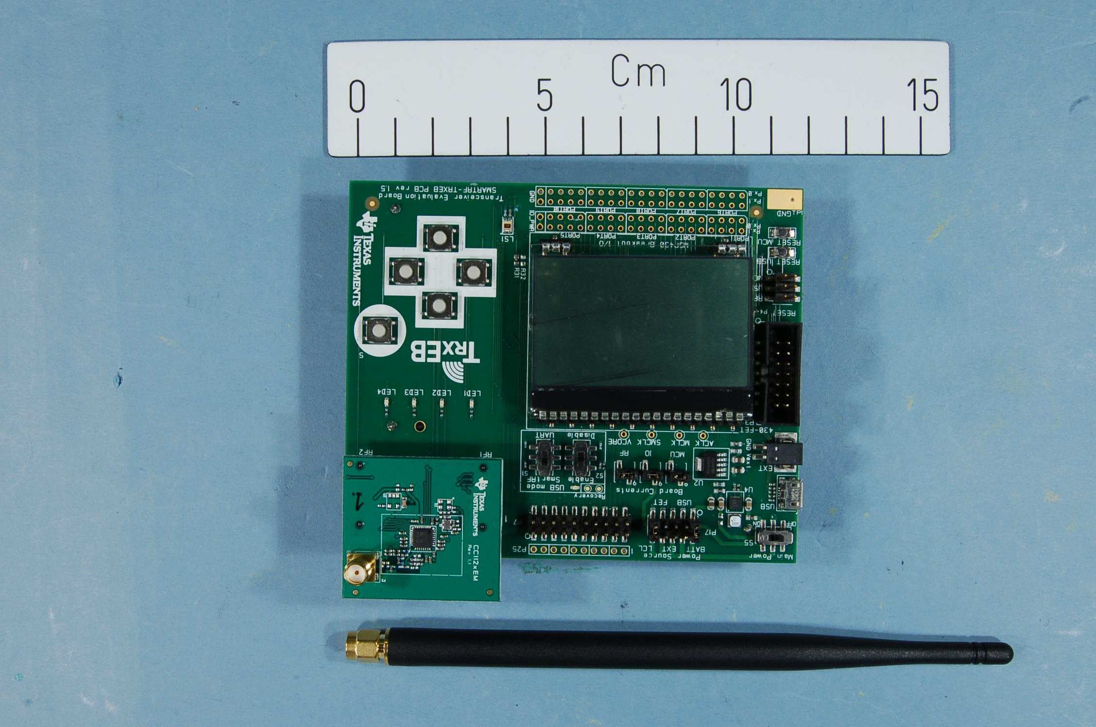
Click to zoom
Application Details
- Equipment Class
- DXT - Part 15 Low Power Transceiver, Rx Verified
- Date of Grant
- Sep 17, 2013
- Application Purpose
- Original Equipment
- Date of Application
- Sep 17, 2013
- Equipment Note
- The CC1175EM-868-915 is a development tool for Texas Instruments sub-1 GHz CC1175 chip.
- Frequency Range
- 903.50000000 - 926.50000000
- Company
- Texas Instruments Inc.
- Country
- United States
Documents & Files
Document Text
Text extracted from the exhibit documents filed with the FCC. Open a document above to read the original.
Users Manual
SWRU291B August 2013 CC1175 Evaluation Module Kit Quick Start Guide 1. Kit Contents 1 x CC1175 Evaluation Module 868/915 MHz 1 x Pulse W5017 Antenna (2 dBi gain) The 868-915 MHz RF board in this kit is FCC and IC certified and it is tested to comply with ETSI/R&TTE over temperatures from 0 to +35°C. FCC/IC Regulatory Compliance FCC Part 15 Class A Compliant IC ICES-003 Class A Compliant 2. How to use the Module The EMK is an add-on kit to supplement the CC1120DK with evaluation boards supporting related devices and additional frequency bands. The CC1175EM boards can be plugged into several development boards from Texas Instruments. Most notably, you can use the SmartRF Transceiver EB (TrxEB), which is included in the CC1120DK. This board has an MSP430 microcontroller which can be used to control the CC1175 radio. Software examples for the TrxEB and MSP430 can be downloaded from the CC1120DK web page (http://www.ti.com/tool/cc1120dk) The TrxEB also makes it easy to control CC1175 from SmartRF™ Studio and it can be used as a general purpose test and development platform. This guide will show how to use the CC1175EM with SmartRF Studio. 3. Plug the EM into a TrxEB Insert the CC1175EM into a TrxEB as shown above. Do not use excessive force on the EM. Remember to mount the antenna. Caution! The kit contains ESD sensitive components. Handle with care to prevent permanent damage. To minimize risk of injury, avoid touching components during operation if symbolized as hot. 4. Select Board Mode Use the switches S1 and S2 to select the operating mode of the TrxEB. For the sake of this quick start guide, please select “Enable” and “SmartRF”. This configuration will make it possible to control the CC1175 device from SmartRF Studio. 5. Power Options There are several ways of applying power to the TrxEB. 2 x 1.5V AA Non-Rechargeable Alkaline Batteries USB (5V through USB plug) External Power Supply (requirements below) MSP430 Debugger When the power source is batteries or USB, the voltage regulators on the TrxEB will set the on- board supply voltage to 3.3VDC. External Power Supply i Requirements: Nom Voltage: 3.3VDC Max Current: 800 mA Efficiency Level V Warning! To minimize risk of personal injury or property damage, never use rechargeable batteries to power the board. 6. Select Power Source Depending on the power source, make sure you connect jumpers to the appropriate pins on the “Power Source” header. For instance, if you use batteries, use a jumper to short-circuit pin 1 and 2 on the header. The last jumper in the row (pin 9- 10) should always be mounted, unless the MSP430 FET is used as the power source. Note that there should only be one active power source at any one time. Do not leave the board powered when unattended. 7. Download and Install Studio Before connecting SmartRF TrxEB to your PC, download and install SmartRF Studio from www.ti.com/smartrfstudio. The USB driver for the evaluation board will be installed together with SmartRF Studio. 8. SmartRF Studio After installing the tool, connect the TrxEB to the PC using the USB cable and start SmartRF Studio. Select the “Sub 1 GHz” tab and double click the highlighted CC1175 device icon. With SmartRF Studio, you can generate the register values required to operate the CC1175 correctly from your embedded software. 9. Test the Radio SmartRF Studio can also be used to actively control the radio and run performance tests. Since CC1175 is a transmitter only, you can use Studio to generate a continuous signal (carrier signal) or send custom packets. The packets can be received by e.g. a CC1120 or CC1121 device connected to another TrxEB. 10. References Please visit http://www.ti.com/product/cc1175 for additional documentation, links to the kit web pages, updated software examples and software tools like SmartRF Studio. You will also find a lot of information on the TI E2E forum at http://e2e.ti.com We hope that you will enjoy working with the CC1175 device. i When using an external power supply, make sure it meets the listed requirements in addition to complying with applicable regional product regulatory and safety certification requirements such as UL, CSA, VDE, CCC, and PSE. EVALUATIONBOARD/KIT/MODULE(EVM)ADDITIONALTERMS TexasInstruments(TI)providestheenclosedEvaluationBoard/Kit/Module(EVM)underthefollowingconditions: Theuserassumesallresponsibilityandliabilityforproperandsafehandlingofthegoods.Further,theuserindemnifiesTIfromallclaims arisingfromthehandlingoruseofthegoods. Shouldthisevaluationboard/kitnotmeetthespecificationsindicatedin theUser’s Guide,theboard/kitmaybereturnedwithin30daysfrom thedateofdeliveryfora fullrefund.THEFOREGOINGLIMITEDWARRANTYISTHEEXCLUSIVEWARRANTYMADEBYSELLERTO BUYERANDISINLIEUOFALLOTHERWARRANTIES,EXPRESSED,IMPLIED,ORSTATUTORY,INCLUDINGANYWARRANTYOF MERCHANTABILITYORFITNESSFORANYPARTICULARPURPOSE.EXCEPTTOTHEEXTENTOFTHEINDEMNITYSETFORTH ABOVE,NEITHERPARTYSHALLBELIABLETOTHEOTHERFORANYINDIRECT,SPECIAL,INCIDENTAL,ORCONSEQUENTIAL DAMAGES. PleasereadtheUser's Guideand,specifically,theWarningsandRestrictionsnoticein theUser's Guidepriortohandlingtheproduct.This noticecontainsimportantsafetyinformationabouttemperaturesandvoltages.ForadditionalinformationonTI's environmentaland/orsafety programs,pleasevisitwww.ti.com/eshorcontactTI. Nolicenseis grantedunderanypatentrightorotherintellectualpropertyrightofTIcoveringorrelatingtoanymachine,process,or combinationin whichsuchTIproductsorservicesmightbeorareused.TIcurrentlydealswitha varietyofcustomersforproducts,and thereforeourarrangementwiththeuseris notexclusive.TIassumesnoliabilityforapplicationsassistance,customerproductdesign, softwareperformance,orinfringementofpatentsorservicesdescribedherein. REGULATORYCOMPLIANCEINFORMATION Asnotedin theEVMUser’s Guideand/orEVMitself,thisEVMand/oraccompanyinghardwaremayormaynotbesubjecttotheFederal CommunicationsCommission(FCC)andIndustryCanada(IC)rules. ForEVMsnotsubjecttotheaboverules,thisevaluationboard/kit/moduleis intendedfo…
Text truncated - open the document above for the full version.
Block Diagram
f = <902MHz – 928MHz> PA FREQUENCY SYNTHESIZER f_internal = <3608MHz – 3712MHz> f_output = <902MHz – 928MHz> MODULATOR RADIO CONTROLLER AND DATA INTERFACE XOSC_Q2 XOSC_Q1 32MHz Crystal OSC CTRL Balun Passive LC network PA
External Photos
FCC ID: ZAT1175EM900 & IC ID: 451H-1175EM900 Project no.: 215159 Page 1 of 2 EXTERNAL PHOTOS – CC1175EM-915 with TrxEB CC1175EM with the W5017 antenna FCC ID: ZAT1175EM900 & IC ID: 451H-1175EM900 Project no.: 215159 Page 2 of 2 CC1175EM docking on TrxEB TrxEB with 2xAA Batteries
ID Label/Location Info
Certification Document Label 1/1 Description of label for CC1175EM-868-915 FCC/IC/CE labeling of product is shown below. There is a separate label with the model name, optional variant designator, revision, serial number, FCC ID and IC number. Texas Instruments Model: CC1175EM-868-915 (xx) Rev. x.x.x S.No.: xxxxxx FCC ID: ZAT1175EM900 IC: 451H-1175EM900 ~ 1 3 m m ~ 25 mm Placement of label on product ~39 mm ~ 3 6 m m T e x a s I n s t r u m e n t s M o d e l : C C 1 1 7 5 E M - 8 6 8 - 9 1 5 ( x x ) R e v . x . x . x S . N o . : x x x x x x F C C I D : Z A T 1 1 7 5 E M 9 0 0 I C : 4 5 1 H - 1 1 7 5 E M 9 0 0 Front side Back side Label manufacturer is Brady. Label part number B473 (http://www.bradyid.com/bradyid/domino/contentView.do/B473.html) with print using series R6000 ribbons (R6007 - http://www.bradyid.com/bradyid/pdpv/IP-R6007.html).
Internal Photos
FCC ID: ZAT1175EM900 & IC ID: 451H-1175EM900 Project no.: 215159 Page 1 of 2 EXTERNAL PHOTOS – CC1175EM-915 with TrxEB CC1175EM with the W5017 antenna
Operational Description
Texas Instruments Norway AS Gaustadalléen 21 0349 Oslo Norway (+47) 22 95 85 44 (+47) 22 95 85 46 Technical Description The CC1175EM-868-915 is an evaluation board for the CC1175 chip from Texas Instruments. The board will only function together with the Transceiver Evaluation Board, SmartRF TrxEB, which is included in e.g. the CC1120DK development kit from Texas Instruments. The CC1175 has a single ended PA output. On the CC1175EM-868-915 board the PA output is transformed to a 50 ohm signal through a passive component (capacitor/inductor) balun. The output of the balun is low pass filtered to reduce harmonic radiation and then connected to an SMA connector. The CC1175EM-868-930 board is equipped with an 868 - 928 MHz whip antenna W5017 from Pulse. The antenna gain is 2 dBi.
Operational Description
L122.A (05/11)1 pulseelectronics.com/products/antennas IP-65 Outdoor 868 & 915 MHz Antenna Pulse Part Number W5012, W5017 San Diego, CA 858 674 8100 Vancouver, WA 360 944 7551Europe 49 7032 7806 0Asia 86 755 33966678North Asia 886 3 4356768China 86 512 6807 9998 Part NumberConnector Type /Gender W5012SMA-RP Male W5017SMA Male Pulse is proud to introduce a ruggedized line of ISM antennas for North American and European applications. These IP-65 rated antennas covering 868 to 928 MHz are suitable for either European or North American operations. The antennas are both supplied in a slim 179 mm (7 inch) package. The W5017 has an SMA-Male connector while the W5012 has SMA RP-Male. The antennas are provided in a UV and IP-65 compliant black plastic radome making them ideal for industrial environments. Applications include Smart Metering, Green Energy, e.g. Solar Inverter Communications, Industrial Control, Remote Control and Wireless M2M. Features - Ingress Protection IP-65 - UV Protection - Antenna Size 0.39 x 7 in (10 x 179 mm) - RoHS Compliant Product Applications - Smart Metering - Industrial Control - Wireless M2M 2 pulseelectronics.com/products/antennas IP-65 Outdoor 868 & 915 MHz Antenna Pulse Part Number W5012, W5017 L122.A (05/11)2 pulseelectronics.com/products/antennas Environmental Specifications Operating Temperature [°C]-40 to +85 Storage Temperature [°C]-40 to +85 Relative Humidity [%]95 Mechanical Specifications Radome Material TPEE Color Black Ingress Protection IP-65 Weight [ozs/g].3 / 9.4 Dimensions [Inches/Meters] 0.39 x 7 [10 x 179] Electrical Specifications Frequency [MHz]868 - 928 Nominal Impedance [Ω]50 Return Loss (dB)-8 Gain (dBi)2 PolarizationOmnidirectional Radiation Patterns -35 -25 -15 -5 5 0 30 60 90270 300 330 868Mhz 898Mhz 928Mhz 120 150 180 210 240 -35 -30 -25 -20 -15 -10 -5 0 5 0 30 60 90270 300 330 868Mhz 898Mhz 928Mhz 120 150 180 210 240 Vertical PlaneHorizontal Plane
Parts List/Tune Up Info
CC1175 EM Rev 1.1.0 868/915 MHz version Including LPFRef. Part name Pcs/unit Description Manufacturer Part number C11 C_47N_0402_X7R_K_25 1 Capacitor, 47n, 0402, X7R, 10%, 25V Murata GRM155R71E473KA88D C12 C_100N_0402_X5R_K_10 0 Do not mount C41 C_10N_0402_X7R_K_25 0 Do not mount C51 C_47N_0402_X7R_K_25 1 Capacitor, 47n, 0402, X7R, 10%, 25V Murata GRM155R71E473KA88D C52 C_2U2_0603_X5R_K_10 1 Capacitor, 2u2, 0603, X5R, 10%, 10V Murata GRM188R61A225KE34D C53 C_0402 0 Do not mount C61 C_220N_0402_X5R_K_10 1 Capacitor, 220n, 0402, X5R, 10 %, 10V Murata GRM155R61A224KE19D C121 C_47N_0402_X7R_K_25 1 Capacitor, 47n, 0402, X7R, 10%, 25V Murata GRM155R71E473KA88D C131 C_47N_0402_X7R_K_25 1 Capacitor, 47n, 0402, X7R, 10%, 25V Murata GRM155R71E473KA88D C151 C_47N_0402_X7R_K_25 1 Capacitor, 47n, 0402, X7R, 10%, 25V Murata GRM155R71E473KA88D C171 C_10N_0402_X7R_K_25 1 Capacitor, 10n, 0402, X7R, 10%, 25V Murata GRM155R71E103KA01D C172 C_100P_0402_NP0_J_50 1 Capacitor, 100p, 0402, NP0, 5% 50V Murata GRM1555C1H101JZ01D C173 C_33P_0402_NP0_J_50 1 Capacitor, 33p, 0402, NP0, 5%, 50V Murata GRM1555C1H330JZ01D C174 C_15P_0402_NP0_J_50 1 Capacitor, 15p, 0402, NP0, 5%, 50V Murata GRM1555C1H150JZ01D C175 C_3P0_0402_NP0_C_50 1 Capacitor, 3p0, 0402, NP0, +-0. 25pF, 50V Murata GRM1555C1H3R0CZ01D C176 C_1P0_0402_NP0_B_50 1 Capacitor, 1p, 0402, NP0, +/-0. 1pF 50V Murata GRM1555C1H1R0BZ01D C177 C_0402 0 Do not mount C181 C_2P2_0402_NP0_C_50 1 Capacitor, 2p2, 0402, NP0, +-0. 25pF, 50V Murata GRM1555C1H2R2CZ01 C191 C_0402 0 Capacitor, general, 0402; Do not mount C211 C_10N_0402_X7R_K_25 1 Capacitor, 10n, 0402, X7R, 10%, 25V Murata GRM155R71E103KA01D C221 C_47N_0402_X7R_K_25 1 Capacitor, 47n, 0402, X7R, 10%, 25V Murata GRM155R71E473KA88D C231 C_1N8_0402_U2J_J_10 1 Capacitor, 1n8, 0402, U2J, 5%, 10V Murata GRM1557U1A182JA01D C251 C_47N_0402_X7R_K_25 1 Capacitor, 47n, 0402, X7R, 10%, 25V Murata GRM155R71E473KA88D C261 C_47N_0402_X7R_K_25 1 Capacitor, 47n, 0402, X7R, 10%, 25V Murata GRM155R71E473KA88D C271 C_47N_0402_X7R_K_25 1 Capacitor, 47n, 0402, X7R, 10%, 25V Murata GRM155R71E473KA88D C281 C_47N_0402_X7R_K_25 1 Capacitor, 47n, 0402, X7R, 10%, 25V Murata GRM155R71E473KA88D C291 C_47N_0402_X7R_K_25 1 Capacitor, 47n, 0402, X7R, 10%, 25V Murata GRM155R71E473KA88D C301 C_15P_0402_NP0_J_50 1 Capacitor, 15p, 0402, NP0, 5%, 50V Murata GRM1555C1H150JZ01D C302 C_0402 0 Capacitor, general, 0402; Do not mount C311 C_15P_0402_NP0_J_50 1 Capacitor, 15p, 0402, NP0, 5%, 50V Murata GRM1555C1H150JZ01D C321 C_100N_0402_X5R_K_10 0 Do not mount C322 C_22P_0402_NP0_J_50 0 Do not mount L1 L_BEAD_102_0402 1 EMI filter bead, 0402 1k ohms Tape GHz Band Gen Use Murata BLM15HG102SN1D L171 L_10N_0402_J_LQW 1 Inductor, 10n, 0402, ±5%, wire-wou nd type Murata LQW15AN10NJ00D L172 L_7N5_0402_G_LQW 1 Inductor, 7n5, 0402, ±2%, wire-wou nd type Murata LQW15AN7N5G00 L173 L_18N_0402_J_LQW 1 Inductor, 18n, 0402, ±5%, wire-wou nd type Murata LQW15AN18NJ00D L174 L_12N_0402_J_LQW 1 Inductor, 12n, 0402, ±5%, wire-wou nd type Murata LQW15AN12NJ00D L191 L_0402 0 Inductor, general, 0402; Do not mount L193 L_0402 0 Inductor, general, 0402; Do not mount L201 L_0402 0 Inductor, general, 0402; Do not mount P1 SMD_SOCKET_2x10 1 SMD pinrow socket, .050 spacing, 2x 10 Samtec SFM-110-02-SM-D-A-K-TR P2 SMD_SOCKET_2x10 1 SMD pinrow socket, .050 spacing, 2x 10 Samtec SFM-110-02-SM-D-A-K-TR P3 SMA_SMD 1 SMA connector, straight SMD-mount R12 R_0_0402 1 Resistor, 0 ohm, 0402 Koa RK73Z1ETTP R141 R_56K_0402_F 1 Resistor, 56k ohms, 0402, ±1% Koa RK73H1ETTP5602F R171 R_10_0402_J 1 Resistor, 10 ohms, 0402, 5% Koa RK73H1ETTP10R0F (±1%) L192 R_0_0402 1 Resistor, 0 ohm, 0402 Koa RK73Z1ETTP C201 R_0_0402 1 Resistor, 0 ohm, 0402 Koa RK73Z1ETTP R321 R_0402 0 Resistor, general, 0402; Do not mount R322 R_0_0402 0 Do not mount U1 CC1175 1 TI tranciver Texas Instruments U2 TPS79930 0 Do not mount X1 X_32.000/10/20/60/10 1 Crystal, 32.000000MHz, FA-128, 10.0pF, +/-10ppm, (FTC: +/-20ppm at -40/85C), 60oh ms Epson Toyocom FA-128, 32MHZ, 10PPM, 10PF, 2x1.6mm, -40/+85C, 60oh ms X2 TG_5021CG 0 Do not mount 39
RF Exposure Info
RF Technical Brief Cover Sheet RF Exposure Compliance (Annex A & B of RSS-102) Nemko AS, Instituttveien 6, 2007 Kjeller, Norway Tel: +47 22 96 03 30, Fax: +47 22 96 05 50 Email : [email protected] RSS 102 Annex A/B July 2013 Annex C – Declaration of RF Exposure Compliance for Exemption from Routine Evaluation Limits ATTESTATION: I attest that the radio communication apparatus meets the exemption from the routine evaluation limits in Section 2.5 of this standard; that the Technical Brief was prepared and the information contained therein is correct; that the device evaluation was performed or supervised by me; that applicable measurement methods and evaluation methodologies have been followed; and that the device meets the SAR and/or RF field strength limits of RSS-102. Signature: Date: 6-Sep-2013 NAME: (Please print or type): Frode Sveinsen TITLE: (Please print or type): Chief engineer COMPANY: (Please print or type): Nemko AS Company Number: 451H Model Number(s): 1175EM-868-915 Manufacturer: Texas Instruments Norway AS Operating frequency: 903.5 – 926.5 MHz Maximum Conducted Output Power: 0.00015 Watts (Peak) Maximum Radiated Output Power: 0.00028 Watts (Peak) Values above are from Nemko test report no. 215159-3. RSS-102, clause 2.5.2: Routine Evaluation Exemption limit for equipment used at a distance greater than 20cm at frequencies above 1.5GHz: 5 Watts EIRP
Schematics
VDD_REG VDD_REG 3V3A VDD_REG VDD_REG 3V3A VDD_REG VDD_REG VDD_REG VDD_REG VDD_REG VDD_REG VDD_REG 1 2 C302C_0402 1 2 C41 C_10N_0402_X7R_K_25 1 2 C131 C_47N_0402_X7R_K_25 1 2 C173C_33P_0402_NP0_J_50 1 23 4 N.C.Vcc OUT GND TCXO X2 TG_5021CG 1 2 C221 C_47N_0402_X7R_K_25 1 2 C211 C_10N_0402_X7R_K_25 12 L1 L_BEAD_102_0402 1 2 L171 L_10N_0402_J_LQW 1 2 C301 C_15P_0402_NP0_J_50 1 2 C231 C_1N8_0402_U2J_J_10 1 2 34 56 78 910 1112 1314 1516 1718 1920 GPIO0 GPIO2 SCLK P1 SMD_SOCKET_2X10 1 2 C261 C_47N_0402_X7R_K_25 1 2 C12 C_100N_0402_X5R_K_10 1 2 C121 C_47N_0402_X7R_K_25 1 2 C11 C_47N_0402_X7R_K_25 1 2 C177 C_0402 1 2 R322R_0_0402 1 2 C171 C_10N_0402_X7R_K_25 1 2 C311 C_15P_0402_NP0_J_50 1 2 3 4 5 OUT IN NR EN GND U2 TPS79930 12 L172 L_7N5_0402_G_LQW 1 2 C52 C_2U2_0603_X5R_K_10 1 2 C61 C_220N_0402_X5R_K_10 12 R12 R_0402 12 L173 L_18N_0402_J_LQW 1 2 C172 C_100P_0402_NP0_J_50 1 2 C51 C_47N_0402_X7R_K_25 1 2 C322 C_22P_0402_NP0_J_50 1 2 C321 C_100N_0402_X5R_K_10 1 2 L193 L_0402 1 2 C281 C_47N_0402_X7R_K_25 1 2 C271 C_47N_0402_X7R_K_25 1 2 C291 C_47N_0402_X7R_K_25 1 2 C251 C_47N_0402_X7R_K_25 1 2 R141 R_56K_0402_F 1 2 C151 C_47N_0402_X7R_K_25 1 2 R321 R_0402 12 34 56 78 910 1112 1314 1516 1718 1920 P2 SMD_SOCKET_2X10 1 2 C53 C_0402 1 2 3 4 5 6 7 8 910111213141516 17 18 19 20 21 22 23 24 25 2627282930313233 RESET GPIO3 MOSI MISO CSN EP EXT_XOSC AVDD_SYNTH DCPL_XOSC AVDD_GUARD DCPL_PFD_CHP CS_N LNA_N LNA_P DVDD LFC_0 RESET_N AVDD_IF PA DVDD NC SI RBIAS DCPL_VCO AVDD_XOSC AVDD_FRONTEND DCPL_DREG XOSC_Q1 XOSC_Q2 SCLK AVDD_SYNTH_CMOS AVDD_PFD_CHP TRX LFC_1 GPIO3 GPIO2 SO/GPIO1GPIO0 U1 CC112X 12 C174 C_15P_0402_NP0_J_50 1 2 L191 L_0402 1 2 3 4 5 P3 SMA_SMD 1 2 R171 R_10_0402_J 12 L174 L_12N_0402_J_LQW 1 2 C175 C_3P0_0402_NP0_C_50 1 2 C181 C_2P2_0402_NP0_C_50 1 2 L192 R_0_0402 1 2 C176 C_1P0_0402_NP0_B_50 FM2 FIDUCIAL_MARK FM1 FIDUCIAL_MARK FM3 FIDUCIAL_MARK 12 L201 L_0402 12 C191 C_0402 12 C201 R_0_0402 1 2 3 4 GND X1X_32.000/10/20/60/10 A3 SCALESHEET APPROVALS DATE REV.DWG NO. DWG COMPANY NAME ISSUED CHECKED DRAWN FSCM NO.SIZE CONTRACT NO. CC1175 uning XTAL: do not mount: X2, C321, C322, R321, R322 CC1175 using TCXO: do not mount: R12, R321, C311, X1. C301: mount 0 Ohm resisitor R12 is a 0ohms shunt resistor that ground the EXT_XOSC pin when TCXO is not mounted. Texas Instruments L1 is a Bead to be mounted if regulator U2 is not mounted, CC1175 ref des will default not use regulator: do not mount U2, C12, C41, C53 TG5021CG is optional: do not mount L1 if regulator U2 is mounted C177: do not mount 1 of 1 CC1175 868/915 MHz frequency band 03236 CC1175 1.1.0 FRS CC1175 TX only. Do not mount: L191, L201, C191, L193
Test Report
Nemko AS, Gaustadalléen 30, P.O.Box 73 Blindern, NO-0314 Oslo Norway T +47 22 96 03 30 F +47 22 96 05 50 Enterprise number NO974404532 Visiting address: Nemko Kjeller, Instituttveien 6, P.O.Box 96, NO-2027 Kjeller Norway T +47 64 84 57 00 F +47 64 84 57 05 Test report no. : 215159-3 Item tested : CC1175EM-868-915 Type of equipment : Low power Transmitter 903.5 – 926.5 MHz FCC ID : ZAT1175EM900 Client : Texas Instruments Norway AS FCC Part 15.249 Low Power Transmitter 902-928 MHz Band RSS-210, Issue 8 Low-Power Licence-exempt Radiocommunications devices 902 – 928 MHz Band 6 September 2013 Authorized by : .............................................. Frode Sveinsen Technical Verificator TEST REPORT FCC part 15.249 Project no.: 215159-3 FCC ID: ZAT1175EM900 & IC ID: 451H-1175EM900 Nemko AS, NO-2027 Kjeller Page 2 (31) CONTENTS 1 GENERAL INFORMATION ...................................................................................................... 3 1.1 Testhouse Info .......................................................................................................................... 3 1.2 Client Information ...................................................................................................................... 3 1.3 Manufacturer ............................................................................................................................. 3 2 Test Information ...................................................................................................................... 4 2.1 Test Item ................................................................................................................................... 4 2.2 Test Environment ...................................................................................................................... 5 2.3 Test Period................................................................................................................................ 5 3 TEST REPORT SUMMARY ..................................................................................................... 6 3.1 General ..................................................................................................................................... 6 3.2 Test Summary ........................................................................................................................... 7 3.3 Description of modification for Modification Filing ..................................................................... 7 3.4 Comments ................................................................................................................................ 7 3.5 Family List Rationale ................................................................................................................ 7 4 TEST RESULTS ....................................................................................................................... 8 4.1 Occupied Bandwidth ................................................................................................................. 8 4.2 Peak Power Output ................................................................................................................. 10 4.3 Spurious Emissions (Radiated) .............................................................................................. 20 5 LIST OF TEST EQUIPMENT .................................................................................................. 29 6 BLOCK DIAGRAM ................................................................................................................. 30 6.1 System set up for radiated measurements ............................................................................. 30 6.2 Test Site Radiated Emission ................................................................................................... 31 TEST REPORT FCC part 15.249 Project no.: 215159-3 FCC ID: ZAT1175EM900 & IC ID: 451H-1175EM900 Nemko AS, NO-2027 Kjeller Page 3 (31) 1 GENERAL INFORMATION 1.1 Testhouse Info Name : Nemko AS Address : Nemko Kjeller Instituttveien 6, Box 96 NO-2027 Kjeller, NORWAY Telephone : +47 64 84 57 00 Fax : +47 64 84 57 05 Email: [email protected] FCC test firm : 994405 IC OATS : 2040D-1 Total Number of Pages: 31 1.2 Client Information Name : Texas Instruments Norway AS Address : Gaustadalléen 21, NO-0349 Oslo, Norway Telephone : +47 22 95 85 44 Fax : +47 22 95 85 46 Contact: Name : Dag Grini Telephone : +47 22 95 83 01 E-mail : [email protected] 1.3 Manufacturer Same as client TEST REPORT FCC part 15.249 Project no.: 215159-3 FCC ID: ZAT1175EM900 & IC ID: 451H-1175EM900 Nemko AS, NO-2027 Kjeller Page 4 (31) 2 Test Information 2.1 Test Item Name : Texas Instruments Model/version : CC1175EM-868-915 FCC ID: ZAT1175EM900 IC ID: 451H-1175EM900 Serial number : 0016 Hardware identity and/or version: 1.1.0 Software identity and/or version : - Frequency Range : 903.5 – 926.5 MHz Number of Channels : 3 Operating Modes : TX only Type of Modulation : 2-FSK Data rate: 1.2kbit/s User Frequency Adjustment : None, Software controlled Rated Output Power : 0.15mW (@50 ohms) Type of Power Supply : Battery (tested with 3.0 V DC, 2x 1.5 V DC) from the mother board TrxEB Antenna Connector : SMA female Antenna type: Pulse W5017, rod antenna Antenna Diversity Supported : None Description of Test Item The CC1175EM-868-915 RF-transmitter module placed on a mother board, TrxEB (Evaluation Board). TEST REPORT FCC part 15.249 Project no.: 215159-3 FCC ID: ZAT1175EM900 & IC ID: 451H-1175EM900 Nemko AS, NO-2027 Kjeller Page 5 (31) 2.2 Test Environment 2.2.1 Normal test condition Temperature: 20 – 22 °C Relative humidity: 21 – 44 % Normal test voltage: 3.0 V DC The values are the limit registered during the test period. 2.3 Test Period Item received date: 2012-10-15 Test period : from 2012-10-17 -2012-10-31 TEST REPORT FCC part 15.249 Project no.: 215159-3 FCC ID: ZAT1175EM900 & IC ID: 451H-1175EM900 Nemko AS, NO-2027 Kjeller Page 6 (31) 3 …
Text truncated - open the document above for the full version.
Test Setup Photos
FCC ID: ZAT1175EM900 & IC ID: 451H-1175EM900 Project no.: 215159 Page 1 of 3 PHOTOS OF TEST SET-UP – CC1175EM-915 with TrxEB Radiated emissions - In band – VP Radiated emissions – In band – HP FCC ID: ZAT1175EM900 & IC ID: 451H-1175EM900 Project no.: 215159 Page 2 of 3 Radiated emissions < 30MHz Radiated emissions 30 – 1000 MHz FCC ID: ZAT1175EM900 & IC ID: 451H-1175EM900 Project no.: 215159 Page 3 of 3 Radiated emissions >1 GHz Radiated emissions > 8.5 GHz
Contact Information
Applicant
Marian Kost(Product Line Manager, Connectivity)
Technical Contact
Texas instruments Norway ASTorstein Ermesjo
[email protected]+47 22 95 89 06
Gaustadalleen 21 · Oslo · Norway
Non-Technical Contact
Nemko USA, Inc.Zarah MacIvor
[email protected]214-629-5683
Test Firm
Nemko ASFrode Sveinsen
Technical Specifications
| # | Rule Parts | Frequency Range | Power Output |
|---|---|---|---|
| 1 | 15C | 903.5 MHz - 926.5 MHz | - |
Other Applications from Texas Instruments Inc.
ZAT-2340R5MODA
Jan 30, 2026CC2340R5MODAN0MHAR
Equipment Class
DTS - Digital Transmission SystemZAT-1312PSIP-3
May 19, 2024CC1312PSIP
Equipment Class
DSS - Part 15 Spread Spectrum TransmitterZAT-1312PSIP-2
Jan 21, 2024CC1312PSIP
Equipment Class
DSS - Part 15 Spread Spectrum Transmitter
ZAT-1312PSIP-1
Jul 09, 2023CC1312PSIP
Equipment Class
DSS - Part 15 Spread Spectrum Transmitter
ZAT7IDEM
Feb 27, 2014The 7IDEM is a development tool for TIs 2.4 GHz 7ID System-on-Chip
Equipment Class
DTS - Digital Transmission System