ZAT2500EMThe CC2500EM is a development tool for TIs 2.4 GHz CC2500 proprietary transceiver
Texas Instruments Inc.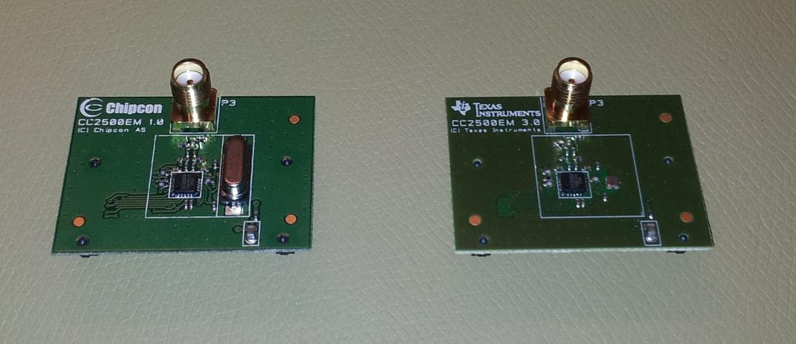
Click to zoom
Application Details
- Equipment Class
- DTS - Digital Transmission System
- Date of Grant
- Jan 23, 2014
- Application Purpose
- Original Equipment
- Date of Application
- Jan 23, 2014
- Equipment Note
- The CC2500EM is a development tool for TIs 2.4 GHz CC2500 proprietary transceiver
- Frequency Range
- 2402.00000000 - 2480.00000000
- Company
- Texas Instruments Inc.
- Country
- United States
Documents & Files
Document Text
Text extracted from the exhibit documents filed with the FCC. Open a document above to read the original.
Users Manual
December 2013 CC2500EMK Quick Start Guide Opening the box and using the modules with SmartRF04EB 1. Kit Contents 2 x CC2500 Evaluation Modules 2 x Antennas (Pulse W1010, 2 dBi) * Documentation The RF boards in this kit are FCC and IC certified and they are tested to comply with ETSI/R&TTE over temperatures from 0 to +35°C. FCC/IC Regulatory Compliance FCC Part 15 Class A Compliant IC ICES-003 Class A Compliant (*) Picture may deviate! 2. How to use the modules The CC2500EM boards can be plugged into several development boards from Texas Instruments. Most notably, you can use the SmartRF04EB, which is included in the CC2500DK. This board lets you run a packet error rate (PER) test, control the device from SmartRF™ Studio and it can be used as a development platform. The board can also be plugged into the SmartRF TrxEB (included in e.g. CC1120DK and CC1200DK) and the MSP430 Experimenter’s Boards. For prototyping with other microcontrollers, plug the EM into the “SoC Battery Board” (www.ti.com/tool/soc-bb). This guide will show how to use the modules together with SmartRF04EB. 3. Plug EM into SmartRF04EB Insert a CC2500EM (EM) with an antenna into the SmartRF04EB (EB). Connect the antenna firmly to the SMA connector on the EM. Caution! The kit contains ESD sensitive components. Handle with care to prevent permanent damage. 4a. Power: Battery There are three different ways of applying power to the EB: The first method involves using an alkaline non- rechargeable battery, either a 9V or a 4xAA battery pack connected to the battery connector on the bottom side of the board Warning! To minimize risk of personal injury or property damage, ONLY use alkaline non- rechargeable batteries. Never use rechargeable batteries to power the board. 4b. Power: DC/External The second method applies DC power using the DC input jack (right in picture, centre is +, sleeve is ground), or by connecting a 4-10V voltage source between the 4-10V and 0V terminals of the power connector (left in picture). It is also possible to connect a 3.3V voltage source between the 3.3V and 0V terminals. The on-board voltage regulators will be bypassed in this case. External Power Supply 1 Requirements: Nom Voltage: 6 VDC Max Current: 800 mA Efficiency Level V 4c. Power: USB The EB can also be powered from the USB bus. Make sure that the SmartRF™ Studio software is installed before connecting the EB to the PC; otherwise you may experience problems in installing it later due to driver issues. Note that if multiple power sources are connected, the source with the highest voltage will power the EB. This means that you should disconnect any attached battery when using a lab supply or USB power; otherwise the battery will be drained. 5. Set Power Switch If a 3.3V source is used as described in 4b above, the switch should be set to the leftmost position. For all other cases, the switch should be set to the rightmost position. This switch can be used to turn off the EB by switching it to the opposite position of that used to turn it on Do not leave the board powered when unattended. 6. Packet Error Rate Test When power is applied to the board, the PER test program will start. You should see the text shown above on the LCD display on both evaluation boards. Press the button marked S1 (lower right corner) to continue. 7. Set Frequency Band Select the desired frequency band of operation by using the joystick. The frequency should match the evaluation module and antenna you are using. Note that the value shown in the display is also the selected value. There is no need to press a button to select or activate the selection. 1 When using an external power supply, make sure it meets the listed requirements in addition to complying with applicable regional product regulatory and safety certification requirements such as UL, CSA, VDE, CCC, and PSE Web sites: www.ti.com/lprf E2E Forum: www.ti.com/lprf-forum Make sure to subscribe to the Low-Power RF Newsletter to receive information about updates to documentation, new product releases, and more. Sign up on the TI web pages. 8. Set Network ID Push the joystick down to display the screen shown above. This lets you set the ID of the node in case you need to run several PER tests simultaneously and you have multiple development kits. Leave this set to 1 for now. 9. Packet Length Push the joystick down to display the screen shown above. This lets you set the length of the packets to be transmitted. The packet length will affect the measured packet error rate. Push the joystick left or right to select the packet length you want to use. 10. Number of Packets Push the joystick down to display the screen shown above. This lets you set the number of packets to be transmitted. Set this to the desired value using the joystick. 11. Select RF Settings Push the joystick down to display the screen shown above. This lets you select preset RF configurations, including modulation and data rate Preset 0: 2-FSK, 2.4 kBaud Preset 1: 2-FSK, 10 kBaud Preset 2: MSK, 250 kBaud Preset 3: MSK, 500 kBaud 12. Select Mode Push the joystick down to display the screen shown above. Use the joystick to select master mode. The EB you have configured now will be the master in the PER test. 13. Configure 2 nd EB Perform steps 3 through 11 on the second EB. Push the joystick down until you get the display shown above. Leave this EB in slave mode. 14. Start PER Push the joystick down on both EBs, and the screen shown above is displayed. Push the joystick right on the slave EB first, and then push the joystick right on the master EB. The PER test will start when the two nodes have successfully connected. 15. Run PER Test The uppermost line of the LCD will show the PER for packets transmitted from the slave to the master, while the second line will show the PER for packets transmitted from the master to the slave. The PER test will end when the number of packets you selected in step 10 is reached or if 100 consecutive packets are lost. 16.…
Text truncated - open the document above for the full version.
Block Diagram
f = <2400MHz – 2483.5MHz> CTRL LNA PA FREQUENCY SYNTHESIZER f_internal = <4800MHz – 4967MHz> f_output = <2400MHz – 2483.5MHz> AAF ADCADC DEMODULATOR MODULATOR RADIO CONTROLLER AND DATA INTERFACE Q I RF_N RF_P I Q CLOCK MUX XOSC_Q2 XOSC_Q1 34,7kHz RC-OSC 26MHz Crystal OSC BALUN ADC CLOCK
External Photos
CC2500EM Rev 3.0 Photos Figure 1 - Rev 2.2 (left) and Rev 3.0 (right) Figure 2 - CC2500EM Rev 3.0 - Bottom view
ID Label/Location Info
Certification Document Label 1/1 Description of label for CC2500EM FCC/IC/CE labeling of product is shown below. There is a separate label with the model name, optional variant designator, revision, serial number, FCC ID and IC number. Texas Instruments Model: CC2500EM (xx) Rev. x.x.x S.No.: xxxxxx FCC ID: ZAT2500EM IC: 451H-2500EM ~ 1 3 m m ~ 25 mm Placement of label on product ~ 39 mm ~ 3 0 m m T e x a s I n s t r u m e n t s M o d e l : C C 2 5 0 0 E M ( x x ) R e v . x . x . x S . N o . : x x x x x x F C C I D : Z A T 2 5 0 0 E M I C : 4 5 1 H - 2 5 0 0 E M Front Back Label manufacturer is Brady. Label part number B473 (http://www.bradyid.com/bradyid/domino/contentView.do/B473.html) with print using series R6000 ribbons (R6007 - http://www.bradyid.com/bradyid/pdpv/IP-R6007.html).
Internal Photos
CC2500EM Rev 3.0 Photos Figure 1 - Rev 2.2 (left) and Rev 3.0 (right) Figure 2 - CC2500EM Rev 3.0 - Bottom view
Operational Description
Texas Instruments Norway AS Gaustadalléen 21 0349 Oslo Norway Tel: (+47) 22 95 85 44 Fax: (+47) 22 95 85 46 Technical Description The CC2500EM is an evaluation board for the CC2500 radio transceiver from Texas Instruments. The CC2500 transceiver has a differential RF output. On the CC2500EM board this differential output is transformed to a single ended, 50 ohm signal through a passive component (capacitor/inductor) balun. The output of the balun is low pass filtered to reduce harmonic radiation and then connected to an SMA connector. The antenna supplied with the board is W1010 from Pulse Electronics. The datasheet of the antenna is attached for further details. CC2500 SWRS040CPage1of89 CC2500 Low-Cost Low-Power2.4 GHzRFTransceiver Applications 2400-2483.5 MHz ISM/SRD band systems Consumerelectronics Wireless game controllers Wireless audio Wireless keyboard and mouse RF enabled remote controls Product Description TheCC2500isa low-cost 2.4 GHz transceiver designed for very low-power wireless appli- cations. The circuit is intended for the2400- 2483.5 MHzISM (Industrial, Scientific and Medical) and SRD (ShortRange Device) frequency band. The RF transceiver is integrated witha highly configurable baseband modem. The modem supports various modulation formats and has a configurable data rate up to 500kBaud. CC2500provides extensive hardware support for packet handling, data buffering, burst transmissions, clear channel assessment, link quality indication,and wake-on-radio. The main operating parameters and the 64- byte transmit/receive FIFOs ofCC2500can be controlled via an SPI interface. In a typical system, theCC2500will be used together with a microcontroller and a few additional passive components. 67891 0 2 0 1 9 1 8 1 7 1 6 Key Features RF Performance High sensitivity (–104 dBm at 2.4 kBaud, 1% packet error rate) Low current consumption (13.3 mA in RX, 250kBaud, input well above sensitivity limit) Programmable output power up to +1 dBm Excellent receiver selectivity and blocking performance Programmable data rate from 1.2 to 500 kBaud Frequency range: 2400–2483.5 MHz Analog Features OOK, 2-FSK, GFSK, and MSK supported Suitable for frequency hopping and multi- channel systems due to a fast settling frequency synthesizer with 90 us settling time AutomaticFrequencyCompensation (AFC) can be used to align the frequency synthesizertothereceivedcentre frequency Integrated analog temperature sensor DigitalFeatures Flexiblesupportforpacketoriented systems: On-chip support for sync word detection, address check, flexible packet length, and automatic CRC handling Efficient SPI interface: All registers can be programmed with one “burst” transfer Digital RSSI output Programmable channel filter bandwidth ProgrammableCarrierSense(CS) indicator CC2500 SWRS040CPage2of89 Programmable Preamble Quality Indicator (PQI) for improved protection against false sync word detection in random noise Support for automatic Clear Channel Assessment (CCA) before transmitting (for listen-before-talk systems) Support for per-package Link Quality Indication (LQI) Optional automatic whitening and de- whitening of data Low-Power Features 400nASLEEPmode current consumption Fast startup time: 240us fromSLEEPto RX or TX mode (measured on EM design) Wake-on-radio functionality for automatic low-power RX polling Separate 64-byte RX and TX data FIFOs (enables burst mode data transmission) General Few external components: Complete on- chip frequency synthesizer, no external filters or RF switch needed Green package: RoHS compliant and no antimony or bromine Small size (QLP 4x4 mm package, 20 pins) Suited for systems compliant with EN 300 328 and EN 300 440 class 2 (Europe), FCC CFR47 Part 15 (US), and ARIB STD- T66 (Japan) Supportforasynchronousand synchronous serial receive/transmit mode for backwards compatibility with existing radio communication protocols CC2500 SWRS040CPage3of89 Abbreviations Abbreviations used in this data sheet are described below. ACPAdjacent Channel PowerMSBMost Significant Bit ADCAnalog to Digital ConverterMSKMinimum Shift Keying AFCAutomatic Frequency Offset CompensationNANot Applicable AGCAutomatic Gain ControlNRZNon Return to Zero (Coding) AMRAutomatic Meter ReadingOOKOn Off Keying ARIBAssociation of Radio Industries and BusinessesPAPower Amplifier BERBit Error RatePCBPrinted Circuit Board BTBandwidth-Time productPDPower Down CCAClear Channel AssessmentPERPacket Error Rate CFRCode of Federal RegulationsPLLPhase Locked Loop CRCCyclic Redundancy CheckPORPower-on Reset CSCarrier SensePQIPreamble Quality Indicator CWContinuous Wave (Unmodulated Carrier)PQTPreamble Quality Threshold DCDirect CurrentRCOSCRC Oscillator DVGADigital Variable Gain AmplifierQPSKQuadrature Phase Shift Keying ESREquivalent Series ResistanceQLPQuad Leadless Package FCCFederal Communications CommissionRCResistor-Capacitor FECForward Error CorrectionRFRadio Frequency FIFOFirst-In-First-OutRSSIReceived Signal Strength Indicator FHSSFrequency Hopping Spread SpectrumRXReceive, Receive Mode 2-FSKFrequency Shift KeyingSMDSurface Mount Device GFSKGaussian shaped Frequency Shift KeyingSNRSignal to Noise Ratio IFIntermediate FrequencySPISerial Peripheral Interface I/QIn-Phase/QuadratureSRDShort Range Device ISMIndustrial, Scientific and MedicalT/RTransmit/Receive LBTListen Before TransmitTXTransmit, Transmit Mode LCInductor-CapacitorVCOVoltage Controlled Oscillator LNALow Noise AmplifierWLANWireless Local Area Networks LOLocal OscillatorWORWake on Radio, Low power polling LQILink Quality IndicatorXOSCCrystal Oscillator LSBLeast Significant BitXTALCrystal MCUMicrocontroller Unit CC2500 SWRS040CPage4of89 Tableof Contents APPLICATIONS...........................................................................................................................................1 PRODUCT DESCRIPTION........................................................................................................................…
Text truncated - open the document above for the full version.
Parts List/Tune Up Info
CC2500EM Parts list Ref. Part namePcs/unitDescriptionManufacturerPart number U1CC25001Single-chip transceiverTICC2500 C41;C51;C111;C141C_100N_0402_X5R_K_104Capacitor, 100n, 0402, X5R, 10%, 10VMurataGRM155R71A104KA01D C121;C131C_100P_0402_NP0_J_502Capacitor, 100p, 0402, NP0, 5% 50VMurataGRM1555C1H101JZ01D C81;C101C_10P_0402_NP0_J_502Capacitor, 10p, 0402, NP0, 5%, 50VMurataGRM1555C1H100JZ01D C122;C132C_1P0_0402_NP0_C_502Capacitor, 1p, 0402, NP0, +/-0.25pF 50VMurataGRM1555C1H1R0CZ01D C124C_1P5_0402_NP0_C_501Capacitor, 1p5, 0402, NP0, +-0.25pF, 50VMurataGRM1555C1H1R5CZ01D C123C_1P8_0402_NP0_C_501Capacitor, 1p8, 0402, NP0, +/-0.25pF 50VMurataGRM1555C1H1R8CZ01D C1C_1U_0805_X7R_K_161Capacitor, 1u, 0805, X7R, 10%, 16VMurataGRM21BR71C105KA01L C91;C151;C181C_220P_0402_X7R_K_503Capacitor, 220p, 0402, X7R, 10%, 50VMurataGRM155R71H221KA01D FM1-3FIDUCIAL_MARK3#N/A#N/A#N/A L121-122;L131L_1N2_0402_S3Inductor, 1n2, 0402, Monolithic type, +/-0.3 nHMurataLQG15HS1N2S02D L1L_BEAD_102_04021EMI filter bead, 0402 1Kohms Tape GHz Band Gen UseMurataBLM15HG102SN1D R171R_56K_0402_F1Resistor, 56k ohms, 0402, ±1% KoaRK73H1ETTP5602F P3SMA_SMD1SMA connector, straight SMD-mountHus-Tsan Group TaiwanSMA-10V21-TGG P1-2SMD_SOCKET_2x102SMD pinrow socket, .050 spacing, 2x10SamtecSFM-110-02-SM-D-A-K-TR X1X_26.000/10/10/40/101Crystal, 26MHz, 10pF, 10PPM, 2x1.6mm SMD, FA128, 60 ohmsEpson ToyocomFA128, 26MHZ, 10PPM, 10PF (9PF) Total no of components29 New XTAL being used Epson Toyocom FA128 26 MHz 2x1.6mm 10pF
RF Exposure Info
SAR Exclusion Justification Test exclusion thresholds for 100 MHz to 6 GHz at test separation distances ≤ 50 mm Guidance document reference: 447498 D01 General RF Exposure Guidance v05r01, page 11, paragraph 4.3.1(1). The 1-g and 10-g SAR test exclusion thresholds for 100 MHz to 6 GHz at test separation distances ≤ 50 mm are determined by: [(max. power of channel, including tune-up tolerance, mW)/(min. test separation distance, mm)] * [ √f(GHz)] ≤ 3.0 for 1 -g SAR and ≤ 7.5 for 10-g extremity SAR, where • f(GHz) is the RF channel transmit frequency in GHz • Power and distance are rounded to the nearest mW and mm before calculation • The result is rounded to one decimal place for comparison • 3.0 and 7.5 are referred to as the numeric thresholds in the step 2 below The test exclusions are applicable only when the minimum test separation distance is ≤ 50 mm and for transmission frequencies between 100 MHz and 6 GHz. When the minimum test separation distance is < 5 mm, a distance of 5 mm according to 5) in section 4.1 is applied to determine SAR test exclusion. SAR test exclusion analysis: Assumptions: Since the exact separation distance may vary from sensor to sensor, the minimum separation distance of 5 mm is assumed per the guidance document. Max. power of channel:1.9 mW Min. separation distance:5 mm Max. frequency:2.48 GHz [(Pwr/Dist)*√Freq.] =0.6 The result of the above SAR threshold calculation demonstrates that the result is less than the 1-g numeric threshold of 3 and the 10-g numeric threshold of 7.5. Conclusion: The above analysis shows that the evaluated device qualifies for exemption from SAR testing. Signed: , Chief Engineer 1/17/2013
Schematics
balun_filter VDD VDD 1 2 3 4 5 6 7 8 9 10 11 12 13 14 15 16 17 18 19 20 21 GND GND XOSC_Q2 CSn RF_P AVDD DVDD GDO2 XOSC_Q1 DGUARD AVDD RF_N RBIAS GDO0(ATEST) DCOUPL AVDD GND AVDD SI SCLK SO(GDO1) U1 CC2500 12 34 56 78 910 1112 1314 1516 1718 1920 GDO0 GDO2 CSn SCLK SI SO P1 SMD_SOCKET_2x10 1 2 C41 C_100N_0402_X5R_K_10 1 2 R171 R_56K_0402_F 1 2 C124 C_1P5_0402_NP0_C_50 1 2 C123 C_1P8_0402_NP0_C_50 1 2345 antenna P3 SMA_SMD 1 2 C51 C_100N_0402_X5R_K_10 1 2 C131 C_100P_0402_NP0_J_50 1 2 C121 C_100P_0402_NP0_J_50 FM1 FIDUCIAL_MARK FM2 FIDUCIAL_MARK FM3 FIDUCIAL_MARK 1 2 L131 L_1N2_0402_S 1 2 C132 C_1P0_0402_NP0_C_50 12 L121 L_1N2_0402_S 1 2 C122 C_1P0_0402_NP0_C_50 12 34 56 78 910 1112 1314 1516 1718 1920 P2 SMD_SOCKET_2x10 1 2 C1 C_1U_0805_X7R_K_16 12 L1 L_BEAD_102_0402 12 L122 L_1N2_0402_S 1 2 C91 C_220P_0402_X7R_K_50 1 2 C151 C_220P_0402_X7R_K_50 1 2 C181 C_220P_0402_X7R_K_50 1 2 C111 C_100N_0402_X5R_K_10 1 2 C141 C_100N_0402_X5R_K_10 1 2 C101 C_10P_0402_NP0_J_50 1 2 C81 C_10P_0402_NP0_J_50 1 2 3 4 X1 X_26.000/10/10/40/10 A3 SCALESHEET APPROVALS DATE REV.DWG NO. DWG COMPANY NAME ISSUED CHECKED DRAWN FSCM NO.SIZE AAC CHIPCON AS CC2500EM 1(1) 3.0 02552 PROJECT NO.
Test Report
Nemko AS, Gaustadalléen 30, P.O.Box 73 Blindern, NO-0314 Oslo NorwayT+47 22 96 03 30F+47 22 96 05 50 Enterprise number NO974404532 Visiting address: NemkoKjeller,Instituttveien6,P.O.Box 96,NO-2027 Kjeller NorwayT+47 64 84 57 00F+47 64 84 57 05 Test report no. :182233-5 Item tested :CC2500EM Type of equipment :2.4GHzTransceiver FCC ID :ZAT2500EM Client :Texas Instruments Norway AS FCCPart 15.247 Digital Transmission System RSS-210, Issue8 Low Power Licence-Exempt Radiocommunication Devices 2013-09-02 Authorized by :.............................................. Frode Sveinsen Technical Verificator TEST REPORT FCC part 15.247 Ref.no.:182233-5 FCC ID:ZAT2500EM NemkoAS, NO-2027 KjellerPage2(31) CONTENTS 1GENERAL INFORMATION......................................................................................................3 1.1Testhouse Info..........................................................................................................................3 1.2Client Information......................................................................................................................3 1.3Responsible Manufacturer (If other than client)........................................................................3 2Test Information......................................................................................................................4 2.1Test Item...................................................................................................................................4 2.2Test Environment......................................................................................................................5 2.2.1Normal test condition...................................................................................................5 2.3Test Period................................................................................................................................5 3TEST REPORT SUMMARY.....................................................................................................6 3.1General.....................................................................................................................................6 3.2Test Summary...........................................................................................................................7 3.3Description of modification for Modification Filing.....................................................................7 3.4Comments................................................................................................................................7 3.5Family List Rational..................................................................................................................7 4TEST RESULTS.......................................................................................................................8 4.1Minimum 6 dB Bandwidth.........................................................................................................8 4.220 dB Bandwidth.......................................................................................................................9 4.3Peak Power Output.................................................................................................................10 4.4Spurious Emissions (Radiated)..............................................................................................14 4.5Receiver Spurious Emissions.................................................................................................26 4.6Power Spectral Density (PSD)................................................................................................28 5LIST OF TEST EQUIPMENT..................................................................................................30 6BLOCK DIAGRAM.................................................................................................................31 6.1Power Line Conducted Emission............................................................................................31 6.2Test Site Radiated Emission...................................................................................................31 TEST REPORT FCC part 15.247 Ref.no.:182233-5 FCC ID:ZAT2500EM NemkoAS, NO-2027 KjellerPage3(31) 1GENERAL INFORMATION 1.1Testhouse Info Name :NemkoAS Address :NemkoKjeller Instituttveien6, Box 96 NO-2027 Kjeller, NORWAY Telephone :+47 64 84 57 00 Fax :+47 64 84 57 05 E-mail:[email protected] FCC test firm:994405 IC OATS:2040D-1 Total Number of Pages:31 1.2Client Information Name :Texas Instruments Norway AS Address :Gaustadalléen 21, NO-0349 Oslo, Norway Telephone :+47 22 95 85 44 Fax :+47 22 95 85 46 Contact: Name :Dag Grini Telephone :+47 22 95 83 01 E-mail :[email protected] 1.3ResponsibleManufacturer(If other than client) Name :/ Address :/ TEST REPORT FCC part 15.247 Ref.no.:182233-5 FCC ID:ZAT2500EM NemkoAS, NO-2027 KjellerPage4(31) 2Test Information 2.1TestItem Name :Texas Instruments FCC ID :ZAT2500EM Model/version :CC2500EM Serial number :/ Hardware identity and/or version:/ Software identity and/or version :/ Frequency Range :2402–2480 MHz Number of Channels :/ Type ofModulation :Digital(2-FSK) Rated output power:/ Data rate:500kbps User Frequency Adjustment :None Type of Power Supply :Primary Batteries (2xAA batteries) Antenna Connector :SMA(Antenna type: W1010) Antenna Diversity Supported :No Desktop Charger :None Description of Test Item The tested EUT is a 2.4GHz transceiverSMA connector. Exposure Evaluation The EUT is exempted from RF Exposure Evaluation. TEST REPORT FCC part 15.247 Ref.no.:182233-5 FCC ID:ZAT2500EM NemkoAS, NO-2027 KjellerPage5(31) 2.2Test Environment 2.2.1Normal test condition Temperature: 20–22C Relative humidity:27–36% Normal test voltage:3.0V DC The radiatedemissions tests were performed with the EUT powered from a test-jig with2xAA primary batteries.Fully charged batteries are used. The values are the limit registered during the test period. 2.3Test…
Text truncated - open the document above for the full version.
Test Setup Photos
FCC ID: ZAT2500EM Project no.: 182233 Page 1 of 1 PHOTOS OF TEST SET-UP – CC2500EM with TrxEB Radiated Emissions 30 - 1000 MHz Radiated Emissions above 1 GHz
Contact Information
Applicant
Marian Kost(Product Line Manager, Connectivity)
Test Firm
Nemko ASFrode Sveinsen
Technical Specifications
| # | Rule Parts | Frequency Range | Power Output |
|---|---|---|---|
| 1 | 15C | 2.40 GHz - 2.48 GHz | 1.88 mW |
Other Applications from Texas Instruments Inc.
ZAT-2340R5MODA
Jan 30, 2026CC2340R5MODAN0MHAR
Equipment Class
DTS - Digital Transmission SystemZAT-1312PSIP-3
May 19, 2024CC1312PSIP
Equipment Class
DSS - Part 15 Spread Spectrum TransmitterZAT-1312PSIP-2
Jan 21, 2024CC1312PSIP
Equipment Class
DSS - Part 15 Spread Spectrum Transmitter
ZAT-1312PSIP-1
Jul 09, 2023CC1312PSIP
Equipment Class
DSS - Part 15 Spread Spectrum Transmitter
ZAT7IDEM
Feb 27, 2014The 7IDEM is a development tool for TIs 2.4 GHz 7ID System-on-Chip
Equipment Class
DTS - Digital Transmission System