ZAT2510SRFThe SmartRFCC2510EM is a development tool for Texas Instruments 2.4 GHz CC2510 System-on-Chip.
Texas Instruments Inc.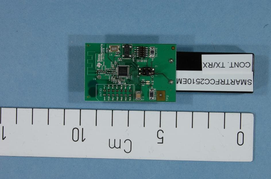
Click to zoom
Application Details
- Equipment Class
- DTS - Digital Transmission System
- Date of Grant
- Sep 02, 2013
- Application Purpose
- Original Equipment
- Date of Application
- Sep 02, 2013
- Equipment Note
- The SmartRFCC2510EM is a development tool for Texas Instruments 2.4 GHz CC2510 System-on-Chip.
- Frequency Range
- 2405.00000000 - 2480.00000000
- Company
- Texas Instruments Inc.
- Country
- United States
Documents & Files
Document Text
Text extracted from the exhibit documents filed with the FCC. Open a document above to read the original.
Users Manual
SWRU235B August 2013 CC2510 Mini Development Kit Quick Start Guide 1 Kit Contents 2 x SmartRFCC2510 target boards 1 x CC Debugger 1 x 10- pin flat cable with 2x5 2.54 mm connector 1 x 10-pin flat cable with 2x5 1.27 mm connector 1 x Converter board 2.54 mm – 1.27 mm connector 1 x Mini USB cable Batteries CD with Evaluation Version of the IAR EW8051 Documentation The hardware in this kit is FCC/IC certified and complies with ETSI/R&TTE over temperature from 0 to +35°C. 2 Running the Preprogrammed Link Test 2.1 Introduction The CC2510 on the SmartRFCC2510 target board is preprogrammed with a link test which operates at 2.42575 GHz, and uses GFSK modulation and a bit rate of 2.4 kbps. The link test runs a point-to-point communication between a Slave and a Master node based on the SimpliciTI 1.1.0 protocol. First the Master and Slave nodes must be configured as described in the following sections. The two nodes will then establish a link. When this link is established, the Master starts to periodically send packets to the Slave. Between each transmission, the Master goes to receive mode and waits 250 ms for an acknowledgement packet from the Slave. The Slave node is in receive mode waiting for packets from the Master. For each received packet, the Slave automatically responds with an acknowledgement packet. 2.2 Powering the boards Place 2 AAA batteries in the battery holder placed on the bottom side of each of the SmartRFCC2510 boards. Place the jumper on the power selection connector P1 between pin 1 and pin 2 on each board. Applying power to the SmartRFCC2510 starts the preprogrammed link test on the CC2510 and the two LEDs on the board are on for 1 s. 2.3 Configure the Master Node Press the MASTER button that is placed on the left hand side of the board. When this button is pushed, the two LEDs on the board will blink rapidly. The Master now waits for a Slave node to establish a link. Note that the board only responds to the first button push. To reconfigure the board, the board must be reset, see point 2.8 in this manual. 2.4 Configure the Slave Node On the other board, press the SLAVE button that is placed on the right side of the board. When the button has been pushed, the two LEDs on this board will blink very slowly until a link with a Master node is established. Note that establishing the link may finish in less than 1 s depending on the environment. 2.5 The LEDs on the Master Node LEDs State Both LEDs blink rapidly The Master is trying to establish a link with a Slave Green LED on for 0.5 s The Master has received an ACK to a packet sent, link ok Red LED on for 0.5 s The Master has not received an ACK to the last 3 packets sent Red LED on for 3 s If the Master does not receive ACKs from the SLAVE in ~70 s, the Master will stop to send packets to save power. Press S1/MASTER to resume the link test Red LED on for 5 s For test only: When the link is established, pressing the S2/SLAVE button turns the red LED on for 5 s 2.6 The LEDs on the Slave node LEDs State Both LEDs blink slowly The Slave is trying to establish a link with a Master Red LED on continuously The link between the Slave and Master is established and the Slave is in RX waiting for packets from the Master Green LED on for 0.5 s while red LED on continuously The Slave has received a packet from the Master and sent an ACK, link is good FCC/IC Regulatory Compliance FCC Part 15 Class A Compliant IC ICES-003 Class A Compliant SWRU235B August 2013 2.7 Range testing The preprogrammed link test is well suited for range testing. Place the Slave in an open field and bring the Master a known distance away. Use the LED signaling to decide the link quality. Note that the environment, antenna, etc greatly affect the range, see DN018 www.ti.com/lit/swra169. 2.8 Resetting the board The recommended reset sequence is: Remove jumper on P1 completely Push one of the buttons to discharge the large capacitor on the power line. If this capacitor is not discharged, the SmartRFCC2510 boards may continue to run the current application until the capacitor is discharged. This may take several seconds. Replace the jumper on P1 to power the board again 3 Using the CC Debugger with the Development Kit 3.1 The CC Debugger The CC Debugger connects to the PC via a mini USB and uses the DEBUG interface to communicate with the radio. The tool can be used for: Programming the flash and debugging an application running on the CC2510. The PC tools available for these purposes are the SmartRF Flash Programmer from Texas Instruments and IAR Embedded Workbench for 8051 from IAR Systems. Testing the radio performance of CC2510 using SmartRF Studio. For more details, please refer to the CC Debugger User’s Guide www.ti.com/lit/swru197 and the CC1110 & CC2510 Mini Development Kit User’s Guide www.ti.com/lit/swru236. 3.2 SmartRF Studio SmartRF Studio can be used for RF testing, evaluation of CC2510 and to find optimal register settings. It is available on http://www.ti.com/smartrfstudio. 3.3 Flash Programmer The Flash Programmer application, available on the kit web page http://focus.ti.com/docs/toolsw/folders/print/flash-programmer.html can be used to program Intel HEX files, read the contents of CC2510 flash, and several other operations. 3.4 IAR Embedded Workbench To develop software, program and debug the CC2510, the IAR Embedded Workbench for 8051 is recommended. An evaluation version of IAR EW8051 is included in the kit. This free evaluation version and also a free code size limited version, can also be downloaded from the web, see www.iar.com/ew8051. A. Available Software and User’s Guides CC1110 & CC2510 Mini DK Software Example User’s Guide and Source Code Source and documentation for the link test for the SmartRFCC2510 target board www.ti.com/lit/zip/swrc133 and www.ti.com/lit/swru237 CC1110 & CC2510 Mini Development Kit User’s Guide More documentation and details on the use of the SmartRFCC2510 target board www.ti.com/lit/swru236 CC1110, CC2510 B…
Text truncated - open the document above for the full version.
Block Diagram
SmartRFCC2510EM CC2510 f = <2400MHz – 2483.5MHz> CTRL LNA PA FREQUENCY SYNTHESIZER f_internal = <4800MHz – 4967MHz> f_output = <2400MHz – 2483.5MHz> AAF ADC ADC DEMODULATOR MODULATOR RADIO CONTROLLER AND DATA INTERFACE QI RF_N RF_P I Q CLOCK MUX X O S C _ Q 2 X O S C _ Q 1 32kHz RC-OSC 26 MHz Crystal OSC BALUN ADC CLOCK 13MHz RC-OSC
Cover Letter(s)
Texas Instruments Norway AS Gaustadalléen 21 0349 Oslo Norway (+47) 22 95 85 44 (+47) 22 95 85 46 August 23, 2013 The SmartRFCC2510EM is a development tool for proprietary solutions in the 2.4GHz ISM band. The CC2510 is a System-on-Chip solution tailored for low power wireless applications. The SmartRFCC2510EM board is equipped with a 2.4 GHz PCB antenna. The board does not have any form of housing or cover. The SmartRFCC2510EM is an engineering development board and cannot be used in an end product. Texas Instruments Norway AS requests Nemko AS to do all necessary testing on the SmartRFCC2510EM to be FCC certified according to FCC CFR 47 Part 15.247 for systems operating in the 2.4GHz ISM band. _________________ Magnus Wines Tools Manager
External Photos
FCC ID:ZAT2510SRF Project no.:182235 Page1of1 INTERNALPHOTOS–SmartRFCC2510EM
ID Label/Location Info
Certification Document Label 1/1 Description of label for SmartRFCC2510EM FCC/IC/CE labeling of product is shown below. The labels are attached to the backside of the printed circuit board. ~ 1 0 1 m m ~ 35 mm Texas Instruments Model: SmartRFCC2510EM Rev.: x.x.x SN.: xxxxxx FCC ID: ZAT2510SRF IC: 451H-2510SRF
Internal Photos
FCC ID:ZAT2510SRF Project no.:182235 Page1of1 INTERNALPHOTOS–SmartRFCC2510EM
Operational Description
Texas Instruments Norway AS Gaustadalléen 21 0349 Oslo Norway (+47) 22 95 85 44 (+47) 22 95 85 46 Technical Description The SmartRFCC2510EM is an evaluation board for the CC2510 chip from Texas Instruments. The board is powered through two 1.5V AAA alkaline batteries. The CC2510 System on Chip has a differential RF output. On the SmartRFCC2510EM board this differential output is transformed to a single ended, 50 ohm signal through a passive component (capacitor/inductor) balun. The output of the balun is low pass filtered to reduce harmonic radiation. The single ended output of the balun is connected to an on- board PCB antenna.
Parts List/Tune Up Info
SmartRFCC2510 Partlist List 1.1 Ref. Part namePcs/unitDescriptionManufacturerPart numberSupplierOrdering code B32XAAA12xAAA battery holder, 2CELL AAA PC MNTKeystone2468Digikey2468K-ND U2CC25101Single-chip transceiver and microcontrollerTexas InstrumentsCC2510Texas InstrumentsCC2510 B2CR2032_SOCKET1Socket for CR2032 buttoncell batteryKeystone3002ELFA69-525-27 C22;C222;C252;C292C_100N_0402_X5R_K_104Capacitor, 100n, 0402, X5R, 10%, 10VMurataGRM155R71A104KA01D C231;C241C_100P_0402_NP0_J_502Capacitor, 100p, 0402, NP0, 5% 50VMurataGRM1555C1H101JZ01D C3C_100U_1210_X5R_M_6p31Capacitor, 100u, 1210, X5R, 20%, 6.3VMurataGRM32EE70G107ME19L C172;C182C_15P_0402_NP0_J_502Capacitor, 15p, 0402, NP0, 5%, 50VMurataGRM1555C1H150JZ01D C1C_1N_0402_NP0_J_501Capacitor, 1n, 0402, NP0, 5%, 50VMurataGRM1555C1H102JA01D C232;C242C_1P0_0402_NP0_C_502Capacitor, 1p, 0402, NP0, +/-0.25pF 50VMurataGRM1555C1H1R0CZ01D C234C_1P5_0402_NP0_C_501Capacitor, 1p5, 0402, NP0, +-0.25pF, 50VMurataGRM1555C1H1R5CZ01D C233C_1P8_0402_NP0_C_501Capacitor, 1p8, 0402, NP0, +/-0.25pF 50VMurataGRM1555C1H1R8CZ01D C302C_1U_0402_X5R_K_6P31Capacitor 1uF, 0402, X5R,10%, 6.3VMurataGRM155R60J105KE19D C192;C262C_220P_0402_NP0_J_502Capacitor, 220p, 0402, NP0, 5%, 50VMurataGRM1555C1H221JA01D C202;C212C_27P_0402_NP0_J_502Capacitor, 27p, 0402, NP0, 5%, 50VMurataGRM1555C1H270JZ01D D1LED_EL19-21SRC1LED, red, 0603, 1.7V, 19mcdEverlightEL19-21SDRC/S530-A3/TR8ELFA75-308-01 D2LED_EL19-21SYGC1LED, green, 0603, 2.0V, 16mcdEverlightEL19-21SYGCELFA75-312-47 L231-232;L241L_1N2_0402_S3Inductor, 1n2, 0402, Monolithic type, +/-0.3 nHMurataLQG15HS1N2S02DACTE P1PINROW_SMD_2X2_2.54MM12x2 pinrow, 2.54mm pitch, SMD typeGradConnBB02-HP041-KB3-060B00Freber S1-2PUSH_BUTTON_SKRK2Momentary push-button, SMD 3.9*2.9*2 mmAlpsSKRKAEE010OXYGEN R2R_0_0402_3PORT1Resistor 3 ports, 0 ohm, 0402KoaRK73Z1ETTPELFA60-470-05 R3-4R_270_0402_F2Resistor, 270 ohms, 0402, ±1% KoaRK73H1E270RF-MR or RK73H1ETTP2700FELFA60-885-61 or 60-477-73 R1R_2K7_0402_F1Resistor, 2k7 ohms, 0402, ±1% KoaRK73H1ETTP2701F ELFA60-482-50 R271R_56K_0402_F1Resistor, 56k ohms, 0402, ±1% KoaRK73H1ETTP5602FELFA60-488-96 DEBUGSTL21110 pins connectorMPE-Garry GmbHSTL21-A01XX-010-TRUFreber X1X_26.000/10/10/10/16A1Cystal, 26.000MHz SMD Crystal, AKER ElectronicsC5S-26.000-16-1010-RAKER ElectronicsC5S-26.000-16-1010-R X2X_32.768/20/50/40/121Crystal, 32.768 kHz, 12.5pF, 20/50 ppm,SMD packageEpsonMC-306ACTEQ13MC3061000314 Total number 38
RF Exposure Info
FCC ID: ZAT2510SRF MPE Calculation for FCC Uncontrolled Environment Formula from page 18 of OET Bulletin 65, Edition 97 -01 where: S = power density P = power input to the antennaG = power gain of the antenna in the direction of i nterest relative to an isotropic radiator R = distance to the center of radiation of the ante nna Source Based Time Averaged Duty Cycle is 100% in ca lculation below Maximum peak output power at antenna input terminal : 6.60 (dBm) Maximum peak output power at antenna input terminal : 0.005 (W) Maximum antenna gain: 0.00 (dBi) Maximum antenna gain: 1.000 (numeric) Prediction distance: 20 (cm) Prediction frequency: 2440 (MHz) Time Averaged Duty Cycle 100 % MPE limit for uncontrolled exposure at prediction f requency: 10.00 (W/m^2) Power density at prediction frequency: 0.0009 (mW/cm^2) Power density at prediction frequency: 0.009 (W/m^2) Maximum allowable antenna gain: 30.41 (dBi) Margin of Compliance: 30.41 (dB) 2 4 R PG S π =
Schematics
P2_2/DC P1_0/LED P0_1 P0_5/SCK P0_4/SSN P0_3/MOSI P1_5 P1_6 P0_7 P1_3/S2 P1_2/S1 P0_0 P1_7 VDD_BAT P0_6 P0_2/MISO P1_1/LED P1_4 P2_1/DD VDD_EXT VDD VDD VDD 1 FM2 FIDUCIAL_MARK_1MM 1 FM3 FIDUCIAL_MARK_1MM 1 2 C3 C_100U_1210_X5R_M_6p3 3 12 + B2 CR2032_SOCKET 12 RESET_N R1 R_2K7_0402_F 1 2 R271 R_56K_0402_F 1 2 + B3 2xAAA_Batt_holder 1 2 3 4 X1 X_26.000/10/10/10/16/A 12 34 VDD_BAT P1 PINROW_SMD_2X2_2.54MM 1 2 D2 LED_EL19-21SYGC 12 P1_0/LED R3 R_270_0402_F 1 2 C233 C_1P8_0402_NP0_C_50 1 2 D1 LED_EL19-21SRC 12 P1_1/LED R4 R_270_0402_F 12 P1_2/S1 S1 PUSH_BUTTON_SKRK 12 P1_3/S2 S2 PUSH_BUTTON_SKRK 14 X2 X_32.768/20/50/40/12 12 34 56 78 910 P2_2/DCP2_1/DD P0_4/SSN P0_5/SCK RESET_N P0_3/MOSI VDD_EXT P0_2/MISO DEBUG STL21 1 2 C1 C_1N_0402_NP0_J_50 12 L232 L_1N2_0402_S 12 34 56 78 910 1112 1314 P1_7 P2_0 P1_6 P0_7 P1_5 P0_6 P1_4 P0_5/SCK P0_0 P0_4/SSNP0_1 P0_3/MOSI P0_2/MISO INTIO PINROW_2X7 1 2 C22 C_100N_0402_X5R_K_10 1 2 C231 C_100P_0402_NP0_J_50 1 2 C232 C_1P0_0402_NP0_C_50 1 FM1 FIDUCIAL_MARK_1MM 1 2 C241 C_100P_0402_NP0_J_50 1 2 C242 C_1P0_0402_NP0_C_50 12 L231 L_1N2_0402_S 1 2 C234 C_1P5_0402_NP0_C_50 1 2 L241 L_1N2_0402_S 1 2 C192 C_220P_0402_NP0_J_50 1 2 C222 C_100N_0402_X5R_K_10 1 2 C252 C_100N_0402_X5R_K_10 1 2 C262C_220P_0402_NP0_J_50 1 2 C292 C_100N_0402_X5R_K_10 1 2 C302 C_1U_0402_X5R_K_6P3 1 2 C202 C_27P_0402_NP0_J_50 1 2 C182 C_15P_0402_NP0_J_50 1 2 C212 C_27P_0402_NP0_J_50 1 2 C172 C_15P_0402_NP0_J_50 1 2 3 4 5 6 7 8 9 10 11 12 13 14 15 16 17 18 19 20 21 22 23 24 25 26 27 28 29 30 31 32 33 34 35 36 37 P2_0 P0_5 P0_0/ATEST P2_0 P0_7 P1_7 P0_6 P2_4/XOSC32_Q2 AVDD P1_6 P2_3/XOSC32_Q1 P1_4 P1_1/LED AVDD XOSC_Q1 P1_0/LED DVDD P1_2 AVDD AVDD P1_3 P0_4 P0_3 DVDD P0_1 P0_2 RESET_N XOSC_Q2 RF_N P1_5 DVDD RF_P RBIAS DGUARD P2_2 P2_1 DCOUPL GND Exposed U2 CC2510 1 2 3 R2 R_0_0402_3PORT 1 2 A1 Antenna_IIFA_1 TP2 Testpoint_pad_small TP3 TESTPIN_SMALL A3 SCALESHEET APPROVALS DATE REV.DWG NO. DWG COMPANY NAME ISSUED CHECKED DRAWN FSCM NO.SIZE CONTRACT NO. Texas Instruments Norway 025114 Default jumper setting: 1-2 DEBUG INTERFACE 1 (1) I/O INTERFACE 1.1 POWER SUPPLY JUMPER SMARTRFCC2510 PUSH BUTTONS RED LED Default resistor setting: 1-2 GREEN LED BATTERY SOLUTION PEH Not mount: INTIO.
Test Report
Nemko AS, Gaustadalléen 30, P.O.Box 73 Blindern, NO-0314 Oslo NorwayT+47 22 96 03 30F+47 22 96 05 50 Enterprise number NO974404532 Visiting address: NemkoKjeller,Instituttveien6,P.O.Box 96,NO-2027 Kjeller NorwayT+47 64 84 57 00F+47 64 84 57 05 Test report no. :182235-5 Item tested :SmartRFCC2510EM Type of equipment :2.4GHz Transceiver FCC ID :ZAT2510SRF Client :Texas Instruments Norway AS FCCPart 15.247 Digital Transmission System RSS-210, Issue8 Low Power Licence-Exempt Radiocommunication Devices 2013-05-16 Authorized by :.............................................. G.Suhanthakumar Technical Verificator TEST REPORT FCC part 15.247 Ref.no.:182235-5 FCC ID:/ NemkoAS, NO-2027 KjellerPage2(30) CONTENTS 1GENERAL INFORMATION......................................................................................................3 1.1Testhouse Info..........................................................................................................................3 1.2Client Information......................................................................................................................3 1.3Responsible Manufacturer (If other than client)........................................................................3 2Test Information......................................................................................................................4 2.1Test Item...................................................................................................................................4 2.2Test Environment......................................................................................................................5 2.3Test Period................................................................................................................................5 3TEST REPORT SUMMARY.....................................................................................................6 3.1General.....................................................................................................................................6 3.2Test Summary...........................................................................................................................7 3.3Description of modification for Modification Filing.....................................................................7 3.4Comments................................................................................................................................7 3.5Family List Rational..................................................................................................................7 4TEST RESULTS.......................................................................................................................8 4.1Minimum 6 dB Bandwidth.........................................................................................................8 4.220 dB Bandwidth.......................................................................................................................9 4.3Peak Power Output.................................................................................................................10 4.4Spurious Emissions (Radiated)..............................................................................................13 4.5Receiver Spurious Emissions.................................................................................................26 4.6Power SpectralDensity (PSD)................................................................................................27 5LIST OF TEST EQUIPMENT..................................................................................................29 6BLOCK DIAGRAM.................................................................................................................30 6.1Test Site Radiated Emission...................................................................................................30 TEST REPORT FCC part 15.247 Ref.no.:182235-5 FCC ID:/ NemkoAS, NO-2027 KjellerPage3(30) 1GENERAL INFORMATION 1.1Testhouse Info Name :NemkoAS Address :NemkoKjeller Instituttveien6, Box 96 NO-2027 Kjeller, NORWAY Telephone :+47 64 84 57 00 Fax :+47 64 84 57 05 E-mail:[email protected] FCC test firm:994405 IC OATS:2040D-1 Total Number of Pages:30 1.2Client Information Name :Texas Instruments Norway AS Address :Gaustadalléen 21, NO-0349 Oslo, Norway Telephone :+4722 95 85 44 Fax :+47 22 95 85 46 Contact: Name :Fredrik Kervel Telephone :+47 22 95 8362 E-mail :[email protected] 1.3ResponsibleManufacturer(If other than client) Name :/ Address :/ TEST REPORT FCC part 15.247 Ref.no.:182235-5 FCC ID:/ NemkoAS, NO-2027 KjellerPage4(30) 2Test Information 2.1TestItem Name :Texas Instruments FCC ID :ZAT2510SRF Model/version :SmartRFCC2510EM Serial number :/ Hardware identity and/or version:/ Software identity and/or version :/ Frequency Range :2405–2480 MHz Number of Channels :/ Type ofModulation :Digital User Frequency Adjustment :None Type of Power Supply :Primary Batteries (2xAAA cells) Antenna Connector :None (Integral Antenna) Antenna Diversity Supported :No Desktop Charger :None Description of Test Item The tested EUT is a 2.4GHz transceiver on a USB Dongle. Exposure Evaluation The EUT is exempted from RF Exposure Evaluation. TEST REPORT FCC part 15.247 Ref.no.:182235-5 FCC ID:/ NemkoAS, NO-2027 KjellerPage5(30) 2.2Test Environment 2.2.1Normal test condition Temperature: 20-22C Relative humidity:42-52% Normal test voltage:2.5 V DC The radiated tests were performed with the EUT powered from primary batteries(2xAAA cells). The values are the limit registered during the test period. 2.3Test Period Item received date:2011-08-15 Test period :from 2011-08-12to 2011-09-22 TEST REPORT FCC part 15.247 Ref.no.:182235-5 FCC ID:/ NemkoAS, NO-2027 KjellerPage6(30) 3TEST REPORT SUMMARY 3.1General Manufacturer:Texas Instruments Model No.:SmartRFCC2510EM Serial No.:/ All measurements are tracable to national standards. The tests were conducted for the purp…
Text truncated - open the document above for the full version.
Test Setup Photos
FCCID:ZAT2510SRF Project no.:182235 Page1of1 PHOTOS OF TEST SET-UP–SmartRFCC2510EM RadiatedEmissions30-1000MHz RadiatedEmissions1-12GHz
Contact Information
Applicant
Marian Kost(Product Line Manager, Connectivity)
Technical Contact
Texas Instruments Norway ASFredrik Kervel
[email protected]+47 22 95 85 44
Gaustadalleen 21 · Oslo · Norway
Test Firm
Nemko ASFrode Sveinsen
Technical Specifications
| # | Rule Parts | Frequency Range | Power Output |
|---|---|---|---|
| 1 | 15C | 2.40 GHz - 2.48 GHz | 4.50 mW |
Other Applications from Texas Instruments Inc.
ZAT-2340R5MODA
Jan 30, 2026CC2340R5MODAN0MHAR
Equipment Class
DTS - Digital Transmission SystemZAT-1312PSIP-3
May 19, 2024CC1312PSIP
Equipment Class
DSS - Part 15 Spread Spectrum TransmitterZAT-1312PSIP-2
Jan 21, 2024CC1312PSIP
Equipment Class
DSS - Part 15 Spread Spectrum Transmitter
ZAT-1312PSIP-1
Jul 09, 2023CC1312PSIP
Equipment Class
DSS - Part 15 Spread Spectrum Transmitter
ZAT7IDEM
Feb 27, 2014The 7IDEM is a development tool for TIs 2.4 GHz 7ID System-on-Chip
Equipment Class
DTS - Digital Transmission System