ZAT2530EMThe CC2530EM is a development tool for TIs 2.4 GHz CC2530 IEEE 802.15.4 System-on-Chip.
Texas Instruments Inc.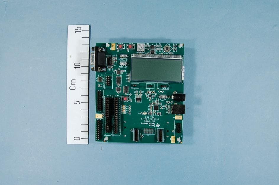
Click to zoom
Application Details
- Equipment Class
- DTS - Digital Transmission System
- Date of Grant
- Jul 25, 2013
- Application Purpose
- Original Equipment
- Date of Application
- Jul 24, 2013
- Equipment Note
- The CC2530EM is a development tool for TIs 2.4 GHz CC2530 IEEE 802.15.4 System-on-Chip.
- Frequency Range
- 2405.00000000 - 2480.00000000
- Company
- Texas Instruments Inc.
- Country
- United States
Documents & Files
Document Text
Text extracted from the exhibit documents filed with the FCC. Open a document above to read the original.
Users Manual
SWRA275A July 2013 CC2530EMK Quick Start Guide 1. Kit Contents 2 x CC2530EM 2 x Pulse W1010 Antennas Documentation The RF boards in this kit are FCC and IC certified and tested to comply with ETSI/R&TTE standards over temperature from 0 to +35°C. The antenna, W1010 from Pulse, is a ¼ wave dipole antenna with 2 dBi gain. FCC/IC Regulatory Compliance FCC Part 15 Class A Compliant IC ICES-003 Class A Compliant 2. Plug EM into SmartRF05EB The CC2530EM, with the antenna mounted on the SMA connector, can be plugged into a SmartRF05EB. The SmartRF05EB is included in the CC2530 Development Kit [2]. Caution! The kit contains ESD sensitive components. Handle with care to prevent permanent damage. 3. Configure the SmartRF05EB Set the EM Selection switch in position SOC/TRX. For best performance, it is recommended to turn off the RS232 interface. Select power source with the jumper on header P11: Position 1-2: Batteries Position 2-3: USB or DC supply Warning! To minimize risk of injury or property damage, never use rechargeable batteries to power the board. Always select a power source that is suitably rated for use with this EVM, not exceeding 20 VDC, with a current output rating between 0 and 1500 mA. Note that there should only be one active power source at any one time. Do not leave the EVM powered when unattended. 4. Packet Error Rate (PER) When power is applied to the SmartRF05EB, the preprogrammed PER test on the CC2530 will start running. The LCD will display the screen as shown in the picture above. The number in the parentheses is the revision of the CC2530. Press Button 1 to continue. 5. Select Channel Select one of the 16 IEEE 802.15.4 channels, with channel number from 11 to 26 (2405-2480 MHz, 5 MHz channel spacing). Select the same channel for both boards. The channel is selected by moving the joystick to the right or left. Press Button 1 to confirm the selection. 6 Set up the Receiver Set one of the boards to operate as receiver. Use the joystick to select mode. Confirm by pressing Button 1. The receiver will now wait for packets from the transmitter. 7. Set up the Transmitter Set the other board to operate as transmitter. Use the joystick to select mode. Confirm the selection by pressing Button 1. On the transmitter node, additional parameters have to be set. On the next screen, select the TX output power (signal strength). Use the joystick to select between -3 dBm, 0 dBm or 4 dBm. Confirm the selection with Button 1. 8. TX: Packets and Rate Next, select burst size (number of packets to send) by using the joystick, either 1000, 10K, 100K or 1M packets. Confirm the selection with Button 1. After selecting burst size, select packet rate; 100, 50, 20 or 10 packet per second. Confirm the selection with Button 1. 9. TX: Start PER Test The transmitter is now configured for the PER test. The PER test is started and stopped by pushing the joystick (as a button). The transmitter will display the number of packets sent during the PER test. After stopping the test, it will start from the beginning if the test is restarted. OFF SOC /TRX SWRA275A July 2013 10. RX: Observe PER The PER test receiver will display the PER value (number of lost and erroneous packets divided by the number of packets sent, displayed as a fraction of 1000). The receiver will also display the number of received packets and a moving average RSSI value based on the last 32 packets. By pressing button 1, all counters on the receiver will be reset and the receiver will restart the PER calculations. 11. SmartRF Studio After running the PER test, the next recommended step is to install SmartRF Studio and to connect the evaluation board to the PC. When installing SmartRF Studio, you will also install the USB drivers required for the SmartRF05EB board. SmartRF Studio can be used for RF testing and evaluation of C2530. SmartRF Studio can be downloaded from www.ti.com/smartrfstudio 12. Flash Programmer Texas Instruments has a simple tool which can be used to program the flash on the CC2530. The Flash Programmer application, available on the kit web page [2], can be used to program Intel HEX files, read the contents of flash and several other operations. Programming of a CC2530 can be done through the SmartRF05EB. Production programming tools are available from TI’s developer network [4]. 13. IAR Embedded Workbench To develop software, program and debug the CC2530, you should use IAR Embedded Workbench for 8051. A free evaluation version of IAR EW8051 is included in the kit. A free, code size limited version can be downloaded from the web. See www.iar.com/ew8051. 14. Packet Sniffer In order to debug RF protocols, it is possible to use TI’s SmartRF Packet Sniffer. You can use the CC2531 USB dongle or the SmartRF05EB with a CC2530EM to capture the packets. 15. Thank You! We hope you will enjoy working with the CC2530 and associated Low-Power RF products from Texas Instruments. A. Available Software CC2530 Software Examples Source code for the PER test and other simple examples for the CC2530 [1] RemoTI™ Network Protocol TIs’ implementation of the ZigBee RF4CE standard: www.ti.com/remoti SimpliciTI™ Network Protocol An RF protocol targeting simple, small RF networks: www.ti.com/simpliciti TIMAC Software TI’s IEEE 802.15.4 medium-access- control stack: www.ti.com/timac Z-Stack™ Software TI’s ZigBee-compliant protocol stack www.ti.com/z-stack B. More information On Texas Instruments’ Low-Power RF web site you will find all our latest products, application and design notes, FAQ section, news and events updates, and much more. Just go to www.ti.com/lprf The Low Power RF Online Community has forums, blogs and videos. Use the forums to find information, discuss and get help with your design. Join us at www.ti.com/lprf-forum The TI LPRF eNewsletter keeps you up to date on e.g. new products, application notes, software and events. Sign up at www.ti.com/lprfnewsletter C. References [1] CC2530 product web page www.ti.com/product/cc2530 [2] C…
Text truncated - open the document above for the full version.
Block Diagram
f = <2405MHz – 2480MHz> CTRL LNA PA FREQUENCY SYNTHESIZER f_internal = <4810MHz – 4960MHz> f_output = <2405MHz – 2480MHz> AAF LPF ADCADCDACDAC DEMODULATOR MODULATOR RADIO CONTROLLER AND DATA INTERFACE Q I Q I RF_N RF_P I Q I Q CLOCK MUX P2.3 P2.4 XOSC_Q2 XOSC_Q1 16MHz RC-OSC 32kHz RC-OSC 32MHz Crystal OSC 32.768kHz Crystal OSC BALUN ADC CLOCK
External Photos
PHOTOSof EUT Project no.:215160 FCC ID: ZAT2530EM Page1of3 PHOTOS– CC2530EM CC2530EM, EUT for radiated measurements PHOTOSof EUT Project no.:215160 FCC ID: ZAT2530EM Page2of3 PULSE W1010Antenna SmartRf05 Evaluation Board–front view PHOTOSof EUT Project no.:215160 FCC ID: ZAT2530EM Page3of3 SmartRf05 Evaluation Board–rear view
ID Label/Location Info
Certification Document Label 1/1 Description of FCC/IC/CE marking on CC2530EM The FCC/IC/CE labeling of the CC2530EM is shown below. The required labels are printed in the silk layer directly on the circuit board. Front side view: Back side view: The board size is approximately 39.3mm x 39.2mm.
Internal Photos
PHOTOSof EUT Project no.:215160 FCC ID: ZAT2530EM Page1 of 1 INTERNALPHOTOS–CC2530EM CC2530EM, EUT for radiated measurements
Operational Description
Texas Instruments Norway AS Gaustadalléen 21 0349 Oslo Norway (+47) 22 95 85 44 (+47) 22 95 85 46 Page 1 of 1 Technical Description The CC2530EM is a development tool for IEEE802.15.4 solutions in the 2.4GHz ISM band. The CC2530 is a System-on-Chip solution tailored for 2.4 GHz ZigBee applications. The CC2530EM board is equipped with a 2.4 GHz whip antenna W1010 from Pulse. The board does not have any form of housing or cover. The CC2530EM is an engineering development board and cannot be used in an end product. The wireless control protocol is based on IEEE802.15.4 at 2.4GHz. The frequency range is 2405MHz to 2480MHz, with 5MHz channel spacing. The PHY layer uses a DSSS technique with a chip rate of 2Mbps and a data rate of 250kbps. The modulation format is half sine shaped O-QPSK. The CC2530 System on Chip has a differential RF output. On the CC2530EM this differential output is fed to a balun and a filter towards the antenna. The antenna gain is 2 dBi.
Parts List/Tune Up Info
CC2530EM Discrete Partlist 1.6 Ref. Part namePcs/unitDescriptionManufacturerPart numberSupplierOrdering code C1 C_2U2_0402_X5R_M_6P3VDC1Capacitor, 2u2, 0402, X5R, +/-20%, 6.3VMurataGRM155R60J225METTI C101; 211; 241; 271; 311 C_100N_0402_X5R_K_105Capacitor, 100n, 0402, X5R, 10%, 10VMurataGRM155R71A104KA01D C221; C231 C_12P_0402_NP0_J_502Capacitor, 12p, 0402, NP0, 5%, 50VMurataGRM1555C1H120JA01D C251; C261 C_18P_0402_NP0_J_502Capacitor, 18p, 0402, NP0, 5% 25VMurataGRM1555C1H180JZ01DELFA65-881-23 C252; C254; C262 C_1P0_0402_NP0_C_503Capacitor, 1p, 0402, NP0, +/-0.25pF 50VMurataGRM1555C1H1R0CZ01D C272 C_220P_0402_NP0_J_501Capacitor, 220p, 0402, NP0, 5%, 50VMurataGRM1555C1H221JA01D C321; C331 C_22P_0402_NP0_J_502Capacitor, 22p, 0402, NP0, 5%, 50VMurataGRM1555C1H220JZ01D C391; C401 C_1U_0402_X5R_K_6P32Capacitor, 1u, 0402, X5R, 10%, 6.3VMurataGRM155R60J105KE19D L1 L_BEAD_102_04021EMI filter bead, 0402 1k ohms Tape GHz Band Gen UseMurataBLM15HG102SN1DACTE L251 L_04020Inductor, general, 0402; Do not mount L253L_1N0_0402_S1Inductor, 1n0, 0402, Monolithic type, +/-0.3 nHMurataLQG15HS1N0S02D L252; L261 L_2N0_0402_S2Inductor, 2n0, 0402, +/-0.3 nHMurataLQG15HS2N0S02D L255L_3N0_0402_S1Inductor, 3n0, 0402, Monolithic type, +/-0.3 nHMurataLQG15HS3N0S02DACTE L256L_04020Inductor, general, 0402; Do not mount P1; P2 SMD_SOCKET_2x102SMD pinrow socket, .050 spacing, 2x10SamtecSFM-110-02-SM-D-A-K-TRAbacus P3 SMA_SMD1SMA connector, straight SMD-mountHus-Tsan Group TaiwanSMA-10V21-TGGEC Partner A/SSMA-10V21-TGG R253R_04020Resistor, general, 0402; Do not mount R301 R_56K_0402_F1Resistor, 56k ohms, 0402, ±1% KoaRK73H1ETTP5602FELFA60-488-96 U1 CC25301Single-chip SoCTICC2530TICC2530 X1 X_32.000/10/20/60/101Crystal, 32.000000MHz, FA-128, 10.0pF, +/-10ppm, (FTC: +/-20ppm at -40/85C), 60ohms Epson ToyocomFA-128, 32MHZ, 10PPM, 10PF, 2x1.6mm, -40/+85C, 60ohmsACTEQ22FA1280009200 X2 X_32.768/20/30/40/12.51Crystal, 32.768kHz, FC-12M, 12,5pFEpson ToyocomFC-12M, 32.768kHz, 20PPM, 12,5pFACTE Total number of components 30
RF Exposure Info
Prediction of MPE limit at a given distance Equation from page 18 of OET Bulletin 65, Edition 97-01 where:S = power density P = power input to the antenna G = power gain of the antenna in the direction of interest relative to an isotropic radiator R = distance to the center of radiation of the antenna Maximum peak output power at antenna input terminal:3.7(dBm)* Maximum peak output power at antenna input terminal:2.3(mW) Antenna gain(maximum):2.4(dBi)* Maximum antenna gain:1.74(numeric) Time Averaging:100(%)* Prediction distance:20(cm)* Prediction frequency:2450(MHz)* MPE limit for uncontrolled exposure at prediction frequency:1.000(mW/cm^2) Power density at prediction frequency:0.001 (mW/cm^2) This equates to:0.01 W/m^2 2 4R PG S
Test Report
Nemko AS, Gaustadalléen 30, P.O.Box 73 Blindern, NO-0314 Oslo Norway T +47 22 96 03 30 F +47 22 96 05 50 Enterprise number NO974404532 Visiting address: Nemko Kjeller, Instituttveien 6, P.O.Box 96, NO-2027 Kjeller Norway T +47 64 84 57 00 F +47 64 84 57 05 Test report no. : 215160-3 Item tested : CC2530EM Type of equipment : 2.4 GHz Transceiver FCC ID : ZAT2530EM Client : Texas Instruments Norway AS FCC Part 15.247 Digital Transmission System RSS-210, Issue 8 Low Power Licence-Exempt Radiocommunication Devices 25 July 2013 Authorized by : .............................................. Frode Sveinsen Technical Verificator TEST REPORT FCC part 15.247 Ref. no.: 215160-3 FCC ID: ZAT2530EM IC: 451H-2530EM Nemko AS, NO-2027 Kjeller Page 2 (69) CONTENTS 1 GENERAL INFORMATION ...................................................................................................... 3 1.1 Testhouse Info .......................................................................................................................... 3 1.2 Client Information ...................................................................................................................... 3 1.3 Responsible Manufacturer (If other than client) ........................................................................ 3 2 TEST INFORMATION ............................................................................................................... 4 2.1 Test Item ................................................................................................................................... 4 2.2 Test Environment ...................................................................................................................... 5 2.3 Test Period................................................................................................................................ 5 3 TEST REPORT SUMMARY ..................................................................................................... 6 3.1 General ..................................................................................................................................... 6 3.2 Test Summary ........................................................................................................................... 7 3.3 Description of modification for Modification Filing ..................................................................... 7 3.4 Comments ................................................................................................................................ 7 3.5 Family List Rational .................................................................................................................. 7 4 TEST RESULTS ....................................................................................................................... 8 4.1 Power Line Conducted Emissions ............................................................................................ 8 4.2 Minimum 6 dB Bandwidth ......................................................................................................... 9 4.3 20 dB Bandwidth ..................................................................................................................... 13 4.4 Peak Power Output ................................................................................................................. 15 4.5 Spurious Emissions (Radiated) .............................................................................................. 25 4.6 Power Spectral Density (PSD) ................................................................................................ 64 5 LIST OF TEST EQUIPMENT .................................................................................................. 68 6 BLOCK DIAGRAM ................................................................................................................. 69 6.1 Power Line Conducted Emission ............................................................................................ 69 6.2 Test Site Radiated Emission ................................................................................................... 69 TEST REPORT FCC part 15.247 Ref. no.: 215160-3 FCC ID: ZAT2530EM IC: 451H-2530EM Nemko AS, NO-2027 Kjeller Page 3 (69) 1 GENERAL INFORMATION 1.1 Testhouse Info Name : Nemko AS Address : Nemko Kjeller Instituttveien 6, Box 96 NO-2027 Kjeller, NORWAY Telephone : +47 64 84 57 00 Fax : +47 64 84 57 05 E-mail: [email protected] FCC test firm : 994405 IC OATS : 2040D-1 Total Number of Pages: 69 1.2 Client Information Name : Texas Instruments Norway AS Address : Gaustadalléen 21, NO-0349 Oslo, Norway Telephone : +47 22 95 85 44 Fax : +47 22 95 85 46 Contact: Name : Dag Grini Telephone : +47 22 95 83 01 E-mail : [email protected] 1.3 Responsible Manufacturer (If other than client) Same as the client. TEST REPORT FCC part 15.247 Ref. no.: 215160-3 FCC ID: ZAT2530EM IC: 451H-2530EM Nemko AS, NO-2027 Kjeller Page 4 (69) 2 TEST INFORMATION 2.1 Test Item Name : Texas Instruments FCC ID : ZAT2530EM IC : 451H-2530EM Model/version : CC2530EM Serial number : - Hardware identity and/or version: - Software identity and/or version : - Frequency Range : 2405 – 2480 MHz Number of Channels : 16 Type of Modulation : 250 kbps, OQPSK (Digital) Conducted Output Power: 2.3 mW (Peak) User Frequency Adjustment : None Type of Power Supply : 3.0V DC (Two AA 1.5 V DC batteries) Antenna Connector : SMA , Antenna type: PULSE W1010 Antenna Diversity Supported : No Desktop Charger : None Description of Test Item The CC2530EM RF-transceiver module is an evaluation module developed for the 2.4 GHz ISM band. It is based on the CC2530 system on- chip device. The physical layer of the radio complies with the IEEE 802.15.4 standard with Direct Sequence Spread Spectrum (DSSS) and offset-QPSK modulation. Exposure Evaluation The EUT is exempted from RF Exposure Evaluation. TEST REPORT FCC part 15.247 Ref. no.: 215160-3 FCC ID: ZAT2530EM IC: 451H-2…
Text truncated - open the document above for the full version.
Test Setup Photos
Photos of Test Set-up Projectno.:215160 FCC ID: ZAT2530EM Page1of2 PHOTOS OF TEST SET-UP–CC2530EM XY plane-Radiated Emissions Radiated emissions-< 30MHz, 10meter Photos of Test Set-up Projectno.:215160 FCC ID: ZAT2530EM Page2of2 RadiatedEmissions30-1000MHz, 3 meter Radiated emissions 1–25GHz, 3 meter& 1 meter
Contact Information
Applicant
Marian Kost(Product Line Manager, Connectivity)
Technical Contact
Texas instruments Norway ASSverre Hellan
[email protected]+47 22 95 89 05
Gaustadalleen 21 · Oslo · Norway
Non-Technical Contact
Nemko USAZarah MacIvor
[email protected]214-629-5683
Test Firm
Nemko ASFrode Sveinsen
Technical Specifications
| # | Rule Parts | Frequency Range | Power Output |
|---|---|---|---|
| 1 | 15C | 2.40 GHz - 2.48 GHz | 2.30 mW |
Other Applications from Texas Instruments Inc.
ZAT-2340R5MODA
Jan 30, 2026CC2340R5MODAN0MHAR
Equipment Class
DTS - Digital Transmission SystemZAT-1312PSIP-3
May 19, 2024CC1312PSIP
Equipment Class
DSS - Part 15 Spread Spectrum TransmitterZAT-1312PSIP-2
Jan 21, 2024CC1312PSIP
Equipment Class
DSS - Part 15 Spread Spectrum Transmitter
ZAT-1312PSIP-1
Jul 09, 2023CC1312PSIP
Equipment Class
DSS - Part 15 Spread Spectrum Transmitter
ZAT7IDEM
Feb 27, 2014The 7IDEM is a development tool for TIs 2.4 GHz 7ID System-on-Chip
Equipment Class
DTS - Digital Transmission System