ZAT2531USBThe CC2531Dongle is a development tool for Texas Instruments 2.4 GHz CC2531 IEEE 802.15.4 System-on-Chip with USB
Texas Instruments Inc.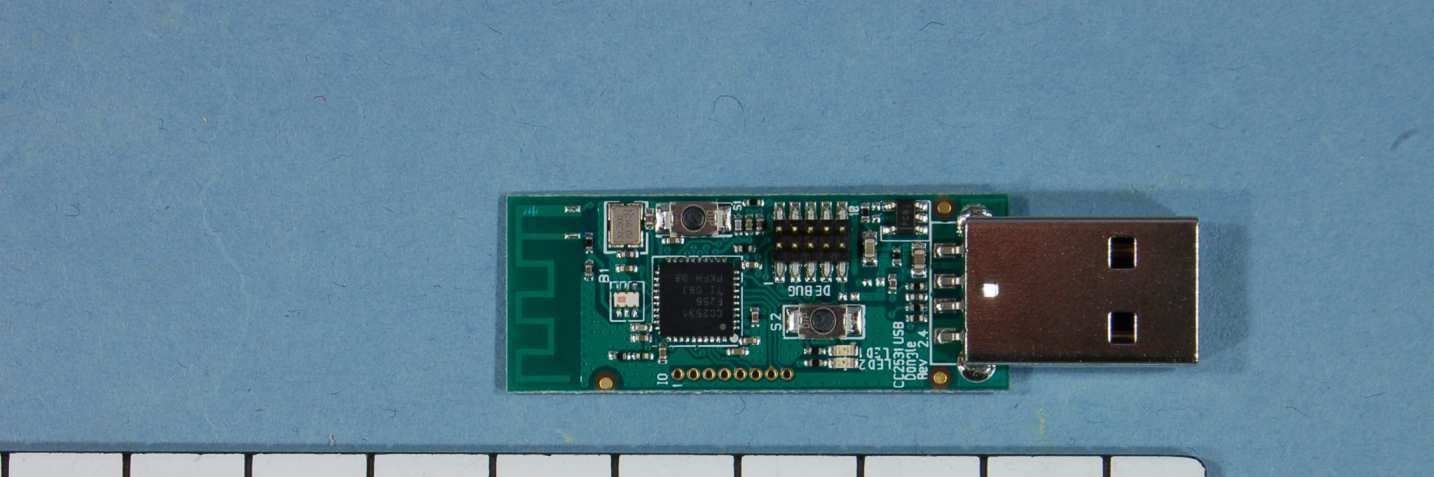
Click to zoom
Application Details
- Equipment Class
- DTS - Digital Transmission System
- Date of Grant
- Apr 14, 2013
- Application Purpose
- Original Equipment
- Date of Application
- Apr 14, 2013
- Equipment Note
- The CC2531Dongle is a development tool for Texas Instruments 2.4 GHz CC2531 IEEE 802.15.4 System-on-Chip with USB
- Frequency Range
- 2425.00000000 - 2475.00000000
- Company
- Texas Instruments Inc.
- Country
- United States
Documents & Files
Document Text
Text extracted from the exhibit documents filed with the FCC. Open a document above to read the original.
Users Manual
SWRA276A March 2013 CC2531 USB Evaluation Kit Quick Start Guide 1. Kit Contents 1 x CC2531 USB Dongle Documentation The RF boards in this kit are FCC and IC certified and tested to comply with ETSI/R&TTE over temperature from 0 to +35°C. Caution! The kit contains ESD sensitive components. Handle with care to prevent permanent damage. 2. Getting Started The CC2531 USB Dongle can be used as a development platform for USB and RF applications. An external development tool, like the CC Debugger, is required to program and debug software running on the CC2531. The CC2531 Dongle comes preprogrammed with software that lets the dongle operate as a packet capture device for the SmartRF Packet Sniffer. This Quick Start Guide will describe how to use the dongle with the packet sniffer and the next steps for your own software development. 3. Install the driver Before plugging the dongle into the PC, please install TI’s SmartRF Packet Sniffer. When installing the Packet Sniffer, you will also automatically install the USB driver required for proper communication between the dongle and the packet sniffer. The Packet Sniffer can be downloaded from www.ti.com/tool/packet-sniffer 4. Insert the USB dongle When inserting the USB dongle into a USB slot, Windows’ new hardware wizard will appear. Select the options for automatic installation and wait for the driver installation to complete. After installation, the Packet Sniffer is ready for use. Caution! This USB dongle has been designed to be powered from a USB port. Do not attempt to connect other power sources to the device. Avoid powering the unit when not in use. 5. Packet Sniffer TI’s SmartRF Packet Sniffer is a convenient tool for debugging of RF protocols. It displays the captured packets and decodes the packet contents depending on what protocol you are running. When starting the packet sniffer, select the protocol as required. The Packet Sniffer for CC2531 supports SimpliciTI, RemoTI and ZigBee PRO, in addition to a generic mode (no packet parsing). 6. Debugging and Programming For software development on the CC2531 an external debugger is necessary. This can be either a SmartRF05EB [3] as shown in the first picture, ...or a CC Debugger [4] as shown in the second picture. SWRA276A March 2013 7. Flash Programmer Texas Instruments has a simple tool which can be used to program the flash on the CC2531. The Flash Programmer application, available on the kit web page [3], can be used to program Intel HEX files, read the contents of flash and several other operations. You will need a SmartRF05EB, a CC Debugger or other programmers from Third Parties [5] to program the device. 8. IAR Embedded Workbench To develop software and debug software running on the CC2531, you should use IAR Embedded Workbench for 8051. A free, code size limited version can be downloaded from the web. See www.iar.com/ew8051. 9. Thank You! We hope you will enjoy working with the CC2531 and associated Low-Power RF products from Texas Instruments. A. Available Software CC2531 USB Firmware Library and Examples. Source code of the USB Protocol Stack including simple HID and CDC examples [2]. RemoTI™ Network Protocol TIs’ implementation of the ZigBee RF4CE standard: www.ti.com/tool/remoti TIMAC Software TI’s IEEE 802.15.4 medium-access-control stack: www.ti.com/tool/timac Z-Stack™ Software TI’s ZigBee-compliant protocol stack www.ti.com/tool/z-stack B. More information On Texas Instruments’ Low-Power RF web site you will find all our latest products, application and design notes, FAQ section, news and events updates, and much more. Just go to www.ti.com/lprf The Low Power RF Online Community has forums, blogs and videos. Use the forums to find information, discuss and get help with your design. Join us at www.ti.com/lprf-forum The TI LPRF eNewsletter keeps you up to date on e.g. new products, application notes, software and events. Sign up at www.ti.com/lprfnewsletter C. References [1] CC2531EMK product web page www.ti.com/tool/cc2531emk [2] CC2531 product web page www.ti.com/product/cc2531 [3] CC2530 Development Kit www.ti.com/tool/cc2530dk [4] CC Debugger www.ti.com/tool/cc-debugger [5] LPRF Developer’s Network www.ti.com/general/docs/gencontent. tsp?contentId=29028 EVALUATION BOARD/KIT/MODULE (EVM) ADDITIONAL TERMS Texas Instruments (TI) provides the enclosed Evaluation Board/Kit/Module (EVM) under the following conditions: The user assumes all responsibility and liability for proper and safe handling of the goods. Further, the user indemnifies TI from all claims arising from the handling or use of the goods. Should this evaluation board/kit not meet the specifications indicated in the User’s Guide, the board/kit may be returned within 30 days from the date of delivery for a full refund. THE FOREGOING LIMITED WARRANTY IS THE EXCLUSIVE WARRANTY MADE BY SELLER TO BUYER AND IS IN LIEU OF ALL OTHER WARRANTIES, EXPRESSED, IMPLIED, OR STATUTORY, INCLUDING ANY WARRANTY OF MERCHANTABILITY OR FITNESS FOR ANY PARTICULAR PURPOSE. EXCEPT TO THE EXTENT OF THE INDEMNITY SET FORTH ABOVE, NEITHER PARTY SHALL BE LIABLE TO THE OTHER FOR ANY INDIRECT, SPECIAL, INCIDENTAL, OR CONSEQUENTIAL DAMAGES. Please read the User's Guide and, specifically, the Warnings and Restrictions notice in the User's Guide prior to handling the product. This notice contains important safety information about temperatures and voltages. For additional information on TI's environmental and/or safety programs, please visitwww.ti.com/eshor contact TI. No license is granted under any patent right or other intellectual property right of TI covering or relating to any machine, process, or combination in which such TI products or services might be or are used. TI currently deals with a variety of customers for products, and therefore our arrangement with the user is not exclusive. TI assumes no liability for applications assistance, customer product design, software performance, or infringement of patents or services described here…
Text truncated - open the document above for the full version.
Block Diagram
CC2531Dongle CC2531 f = <2402MHz – 2480MHz> CTRL LNA PA FREQUENCY SYNTHESIZER f_internal = <4804MHz – 4960MHz> f_output = <2402MHz – 2480MHz> AAF LPF ADC ADC DAC DAC DEMODULATOR MODULATOR RADIO CONTROLLER AND DATA INTERFACE QI QI RF_N RF_P I Q I Q CLOCK MUX X O S C _ Q 2 X O S C _ Q 1 16MHz RC-OSC 32kHz RC-OSC 32MHZ Crystal OSC BALUN ADC CLOCK
ID Label/Location Info
Certification Document Label 1/1 Description of label on CC2531Dongle FCC/IC/CE labeling of product is shown below. The label contains the model name, optional variant designator, revision number, serial number, FCC ID and IC number. Texas Instruments Model: CC2531Dongle (xx) Rev. x.x.x S.No.: xxxxxx FCC ID: ZAT2531USB IC: 451H-2531USB ~ 1 3 m m ~ 25 mm Placement of label on product 16 mm 4 1 m m 1 5 m m 11 mm T e x a s I n s t r u m e n t s M o d e l : C C 2 5 3 1 D o n g l e ( x x x ) R e v . x . x . x S . N o . : x x x x x x F C C I D : Z A T 2 5 3 1 U S B I C : 4 5 1 H - 2 5 3 1 U S B
Internal Photos
TEST REPORT ETSI EN 300 328 Project No.: 182230-3 Nemko AS, NO-2027 Kjeller Page 44 (46) 6 PHOTOGHRAPHS OF EUT CC2531 – USB Dongle
Operational Description
Texas Instruments Norway AS Gaustadalléen 21 0349 Oslo Norway (+47) 22 95 85 44 (+47) 22 95 85 46 Page 1 of 1 Technical Description The CC2531Dongle is an evaluation board for the CC2531 chip from Texas Instruments. The board is powered through USB. The CC2531System on Chip has a differential RF output. On the CC2531Dongle board this differential output is transformed to a single ended, 50 ohm signal through an integrated balun from Johansson Technologies (2450BM15A0002). Additionally the balun has integrated filter components which greatly reduces harmonic radiation. The single ended output of the balun is connected to an on-board PCB antenna.
RF Exposure Info
SAR Exemption FCC ID.: ZAT2531USB Applicant: Texas Instruments, Inc. Type of Device: USB Dongle Analysis: The product is a USB dongle that is used for development of rf transmitter circuits and software. The device is part of an Evaluation Module (EVM) kit and is intended only for use by developers. Since the dongle could be used in any laptop computer and a specific minimum separation distance cannot be determined, the minimum separation of 5 mm is used per 447498 10 D01 General RF Exposure Guidance v05. The SAR exclusion is calculated using the formula from page 10 of 447498 10 D01. From test report 182230‐5, issued by Nemko AS, the maximum measured rf output power is 4.47 mW. Therefore: ܹ݉5 ݉݉5 ൨െ √ 2.4ൌ1െ1.5ൌ െ0.5 This is below the threshold of 3.0 for 1‐g SAR and 7.5 for 10‐g SAR.
Schematics
VOLTAGE REGULATOR SoC periferials RF-SoC PART P1_1/LED P1_2 P0_2 P0_3 PA_DM P0_0 PA_DP P1_4 P1_5 P1_6 P1_7 P2_1 P2_2 RESET_N P0_4 P0_5 P1_0/LED P1_3 P0_0 P0_2 P0_3 P0_4 P0_5 P1_0/LED P1_1/LED P1_2 P1_3 P1_4 P1_5 P1_6 P1_7 P2_1 P2_2 PA_DP PA_DM RESET_N 1 FM2 FIDUCIAL_MARK_1mm 1 FM3 FIDUCIAL_MARK_1mm 1 FM1 FIDUCIAL_MARK_1mm Including PCB antenna CONTRACT NO. SIZEFSCM NO. DRAWN CHECKED ISSUED COMPANY NAME DWG DWG NO.REV. DATE APPROVALS SHEETSCALE A4 1(4) - USB Connector - Buttons - LEDs - SMD sockets Generated voltage: 3.3 V for CC2531 Texas Instruments CC2531 USB dongle 2.4 025104 TIK MAP 3.3VVCC_EXT VBUS Gnd OutIn /ENNC VREG U2 TPS76933 1 2 R2R_0402 1 2 C2 C_4U7_0603_X5R_K_6 1 2 C1 C_1U_0603_X5R_L_6P3 1 2 R1 R_2_0402_F 12 R3 R_0_0402 1 2 C3 C_0402 CONTRACT NO. SIZEFSCM NO. DRAWN CHECKED ISSUED COMPANY NAME DWG DWG NO.REV. DATE APPROVALS SHEETSCALE A4 CC2531 USB DONGLE VOLTAGE REGULATOR Not mount: C3, R2 2(4) To CC2531 From PC Texas Instruments 2.4 025104 TIK MAP P0_0 P0_2 P0_3 P0_4 P0_5 P1_0/LED P1_1/LED P1_2 P1_3 P1_4 P1_5 P1_6 P1_7 P2_1 P2_2 PA_DP PA_DM RESET_N 3.3V VCC 1 2 C241 C_100N_0402_X5R_K_10 1 2 C211C_100N_0402_X5R_K_10 C5 C_0P5_0402_NP0_B_50 1 2 C311C_100N_0402_X5R_K_10 1 2 C271C_100N_0402_X5R_K_10 1 2 C221 C_27P_0402_NP0_J_50 1 2 C4 C_2U2_0402_X5R_M_4VDC 1 2 C272C_220P_0402_NP0_J_50 1 2 C391 C_1U_0402_X5R_K_6P3 1 2 C201 C_1N_0402_NP0_J_50 1 2 R301 R_56K_0402_F 1 2 C401 C_1U_0402_X5R_K_6P3 1 2 C41 C_10P_0402_NP0_J_50 3 1 X1X_32.000/10/15/30/16 1 2 3 4 5 6 7 8 9 10 11 12 13 14 15 16 17 18 19 20 21 22 23 24 25 26 27 28 29 30 31 32 33 34 35 36 37 38 39 40 41 P0_5 P1_5 RBIAS AVDD2 P0_6 P0_7 P0_4 P1_6 P0_2 P1_7 P0_0 DVDD_USB DGND_USB P0_1 P0_3 GND AVDD4 AVDD3 DCOUPL P1_0 P1_4 AVDD1 RESET_N P2_4 P1_1 P1_3 P1_2 RF_P P2_2 P2_3 P2_0 RF_N P2_1 DVDD2 DVDD1 AVDD5 AVDD6 XOSC_Q2 XOSC_Q1 USB_M USB_P U1 CC2531 1 2 C231 C_27P_0402_NP0_J_50 12 L1 L_BEAD_102_0402 12 A2 ANTENNA_IIFA_1_LEFT 2 R9 R_0_0402 1 2 3 4 56 B1 JTI_2450BM15A0002 12 R201 R_2K2_0402_G 1 2 C101 C_100N_0402_X5R_K_10 L301 L_6N8_0402_J CONTRACT NO. SIZEFSCM NO. DRAWN CHECKED ISSUED COMPANY NAME DWG DWG NO.REV. DATE APPROVALS SHEETSCALE A4 3(4) Texas Instruments CC2531 USB DONGLE RF-PART 2.4 025104 TIK MAP P1_1/LED P1_2 P0_2 P0_3 PA_DM P0_0 PA_DP P1_4 P1_5 P1_6 P1_7 P2_1 P2_2 RESET_N P0_4 P0_5 P1_0/LED P1_3 3.3V VBUS 3.3V 3.3V VCC_EXT 8 7 6 5 4 3 2 1 IO BL_31_008U_NO_SILK 1 2 3 4 5 6 D- VBUS Shield GND D+ Shield P1 USB_A 12 R21 R_33_0402_G 12 R31 R_33_0402_G 12 R91 R_0_0402 1 2 R71 R_270_0402_F 1 2 D2LED_EL19-21SYGC 1 2 R92R_0402 1 2 C31 C_47P_0402_NP0_J_50 1 2 R11 R_270_0402_F 1 2 R32R_1K5_0402_G 12 S2 PUSH_BUTTON_SKRK 12 S1 PUSH_BUTTON_SKRK 1 2 D1LED_EL19-21SURC 12 34 56 78 910 DEBUG STL21 1 2 C21 C_47P_0402_NP0_J_50 CONTRACT NO. SIZEFSCM NO. DRAWN CHECKED ISSUED COMPANY NAME DWG DWG NO.REV. DATE APPROVALS SHEETSCALE A4 4(4) LED_Green CC2531 USB dongle USB circuitry SoC debug/flash button_P_1_3 Texas Instruments LED_Red button_P_1_2 2.4 025104 USB Interface Not mount: R92, IO TIK Additional testpins MAP
Test Report
Nemko AS, Gaustadalléen 30, P.O.Box 73 Blindern, NO-0314 Oslo Norway T +47 22 96 03 30 F +47 22 96 05 50 Enterprise number NO974404532 Visiting address: Nemko Kjeller, Instituttveien 6, P.O.Box 96, NO-2027 Kjeller Norway T +47 64 84 57 00 F +47 64 84 57 05 Test report no. : 182230-5 Item tested : CC2531Dongle Type of equipment : 2.4GHz Transceiver FCC ID : ZAT2531USB Client : Texas Instruments Norway AS FCC Part 15.247 Digital Transmission System RSS-210, Issue 8 Low Power Licence-Exempt Radiocommunication Devices 2013-04-09 Authorized by : .............................................. G. Suhantakumar Technical Verificator TEST REPORT FCC part 15.247 Ref. no.: 182230-5 FCC ID: ZAT2531USB Nemko AS, NO-2027 Kjeller Page 2 (33) CONTENTS 1 GENERAL INFORMATION ...................................................................................................... 3 1.1 Testhouse Info .......................................................................................................................... 3 1.2 Client Information ...................................................................................................................... 3 1.3 Responsible Manufacturer (If other than client) ........................................................................ 3 2 Test Information ...................................................................................................................... 4 2.1 Test Item ................................................................................................................................... 4 2.2 Test Environment ...................................................................................................................... 5 2.3 Test Period................................................................................................................................ 5 3 TEST REPORT SUMMARY ..................................................................................................... 6 3.1 General ..................................................................................................................................... 6 3.2 Test Summary ........................................................................................................................... 7 3.3 Description of modification for Modification Filing ..................................................................... 7 3.4 Comments ................................................................................................................................ 7 3.5 Family List Rational .................................................................................................................. 7 4 TEST RESULTS ....................................................................................................................... 8 4.1 Power Line Conducted Emissions ............................................................................................ 8 4.2 Minimum 6 dB Bandwidth ....................................................................................................... 10 4.3 20 dB Bandwidth ..................................................................................................................... 11 4.4 Peak Power Output ................................................................................................................. 12 4.5 Spurious Emissions (Radiated) .............................................................................................. 15 4.6 Receiver Spurious Emissions ................................................................................................. 28 4.7 Power Spectral Density (PSD) ................................................................................................ 30 5 LIST OF TEST EQUIPMENT .................................................................................................. 32 6 BLOCK DIAGRAM ................................................................................................................. 33 6.1 Power Line Conducted Emission ............................................................................................ 33 6.2 Test Site Radiated Emission ................................................................................................... 33 TEST REPORT FCC part 15.247 Ref. no.: 182230-5 FCC ID: ZAT2531USB Nemko AS, NO-2027 Kjeller Page 3 (33) 1 GENERAL INFORMATION 1.1 Testhouse Info Name : Nemko AS Address : Nemko Kjeller Instituttveien 6, Box 96 NO-2027 Kjeller, NORWAY Telephone : +47 64 84 57 00 Fax : +47 64 84 57 05 E-mail: [email protected] FCC test firm : 994405 IC OATS : 2040D-1 Total Number of Pages: 33 1.2 Client Information Name : Texas Instruments Norway AS Address : Gaustadalléen 21, NO-0349 Oslo, Norway Telephone : +47 22 95 85 44 Fax : +47 22 95 85 46 Contact: Name : Fredrik Kervel Telephone : +47 22 95 8362 E-mail : [email protected] 1.3 Responsible Manufacturer (If other than client) Name : / Address : / TEST REPORT FCC part 15.247 Ref. no.: 182230-5 FCC ID: ZAT2531USB Nemko AS, NO-2027 Kjeller Page 4 (33) 2 Test Information 2.1 Test Item Name : Texas Instruments FCC ID : ZAT2531USB Model/version : CC2531Dongle Serial number : / Hardware identity and/or version: / Software identity and/or version : / Frequency Range : 2425 – 2475 MHz Number of Channels : 3 Type of Modulation : Digital (QPSK) User Frequency Adjustment : None Type of Power Supply : Powered from USB Antenna Connector : None (PCB Antenna) Antenna Diversity Supported : No Desktop Charger : None Description of Test Item The tested EUT is a 2.4GHz transceiver on a USB Dongle. Exposure Evaluation The EUT is exempted from RF Exposure Evaluation. TEST REPORT FCC part 15.247 Ref. no.: 182230-5 FCC ID: ZAT2531USB Nemko AS, NO-2027 Kjeller Page 5 (33) 2.2 Test Environment 2.2.1 Normal test condition Temperature: 20 - 22 °C Relative humidity: 42 - 52 % Normal test voltage: 4.5 V DC The radiated emissions tests were performed with the EUT powered…
Text truncated - open the document above for the full version.
Test Setup Photos
TEST REPORT ETSI EN 300 328 Project No.: 182230-3 Nemko AS, NO-2027 Kjeller Page 43 (46) Test Setups Radiated measurements Climatic measurements
Contact Information
Applicant
Marian Kost(Product Line Manager, Connectivity)
Test Firm
Nemko ASFrode Sveinsen
Technical Specifications
| # | Rule Parts | Frequency Range | Power Output |
|---|---|---|---|
| 1 | 15C | 2.42 GHz - 2.48 GHz | 4.00 mW |
Other Applications from Texas Instruments Inc.
ZAT-2340R5MODA
Jan 30, 2026CC2340R5MODAN0MHAR
Equipment Class
DTS - Digital Transmission SystemZAT-1312PSIP-3
May 19, 2024CC1312PSIP
Equipment Class
DSS - Part 15 Spread Spectrum TransmitterZAT-1312PSIP-2
Jan 21, 2024CC1312PSIP
Equipment Class
DSS - Part 15 Spread Spectrum Transmitter
ZAT-1312PSIP-1
Jul 09, 2023CC1312PSIP
Equipment Class
DSS - Part 15 Spread Spectrum Transmitter
ZAT7IDEM
Feb 27, 2014The 7IDEM is a development tool for TIs 2.4 GHz 7ID System-on-Chip
Equipment Class
DTS - Digital Transmission System