ZAT2538EMThe CC2538EM is a development tool for the 2.4 GHz CC2538 IEEE802.15.4 System-on-Chip from TI.
Texas Instruments Inc.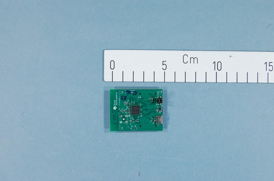
Click to zoom
Application Details
- Equipment Class
- DTS - Digital Transmission System
- Date of Grant
- Mar 14, 2013
- Application Purpose
- Original Equipment
- Date of Application
- Mar 13, 2013
- Equipment Note
- The CC2538EM is a development tool for the 2.4 GHz CC2538 IEEE802.15.4 System-on-Chip from TI.
- Frequency Range
- 2405.00000000 - 2480.00000000
- Company
- Texas Instruments Inc.
- Country
- United States
Documents & Files
Document Text
Text extracted from the exhibit documents filed with the FCC. Open a document above to read the original.
Users Manual
March 2013 Web sites: www.ti.com/lprf E2E Forum: www.ti.com/lprf-forum Make sure to subscribe to the Low-Power RF Newsletter to receive information about updates to documentation, new product releases, and more. Sign up on the TI web pages. CC2538 Development Kit Quick Start Guide Opening the Box and Running the Packet Error Rate Test 1. Kit Contents 2 x SmartRF06 Evaluation Boards (SRF06EB) 2 x CC2538 Evaluation Modules (CC2538EM) 1 x CC2531 USB dongle (sniffer) 2 x Micro USB Cables Documentation The RF boards in this kit are FCC and IC certified and tested/comply with ETSI/R&TTE over temperature from 0 to 35°C. 2. SmartRF06EB Overview 3. Plug the EM into the 06EB Insert a CC2538EM board into the SmartRF06EB as shown above. Caution! The kit contains ESD sensitive components. Handle with care to prevent permanent damage. To minimize risk of injury, avoid touching components during operation if symbolized as hot. 5. Power Options There are several ways of applying power to the TrxEB. USB (5V) 2 x 1.5 V AAA batteries 1 x 3.0 V CR2032 coin cell battery External regulated power supply There are voltage regulators on the SmartRF06EB that will set the on-board voltage to 2.1 V or 3.3 V. Warning! To minimize risk of injury or property damage, never use rechargeable batteries to power the board. Always select a power source that is suitably rated for use with this EVM, not exceeding 3.6 VDC, with a current output rating between 0 and 500 mA. 6. Select Power Source The power source is selected using the Source switch on the left hand side of the SmartRF06EB. In “USB” position, the EM is powered over USB, running at 3.3 V. In “BAT” position, the board is powered from batteries or an external source, running at 2.1 V. The 2.1 V regulator can be bypassed by shorting the pins on the “regulator bypass” jumper. In this case, the EM is powered directly from the external source or batteries. Note that there should only be one active power source at any one time. Do not leave the EVM powered when unattended. 7. Welcome Screen Turn on power with the Main Power switch. You should now see the Texas Instruments logo and a short description of the buttons on the LCD. Pushing any of the five buttons on the board will take you to the main menu. NB! If you don’t see anything on the screen make sure the board is correctly powered (see step 5 and 6 above). 8. Select Channel Select which channel to use for the test. 9. Select Mode One of the boards must operate as a transmitter and the other as a receiver. Select transmitter on one board ... ... and receiver on the other board. The receiver is now configured. Buttons EM Connectors Micro SD card reader USB Main Power Switch Emulator LEDs LCD LEDs 10-pin ARM Debug Connector EM Breakout Power Selection 20-pin ARM-JTAG Connector 10. Select TX Power On the transmitter, select desired output power. 11. Select Burst Size On the transmitter, select the desired burst size, that is, the number of packets to transmit. 12. Select Packet Rate On the transmitter, select the desired packet rate. 13. Start Sending Packets The transmitter is now configured and in idle state. Sending packets is started/stopped by pressing the Select button. 15. PER Test Results On the receiver, the statistics window will show the error rate based on the number of lost or erreneous packets divided by the total number of packets that should have been received. 18. References Please visit www.ti.com and http://www.ti.com/tool/cc2538dk On the kit product page, you will find additional documentation, links to updated software examples and software tools like SmartRF Studio. You will also find a lot of information on the TI E2E forum at http://e2e.ti.com We hope that you will enjoy working with the CC2538 device. 17. Troubleshooting It you are experiencing problems with this test, please check the following: Nothing is shown in the display! Make sure the board is powered correctly (see steps 5 and 6 above). Please visit the kit web page and check for updated SW and documentation. Updated SW can be downloaded to the device using IAR EWARM or SmartRF Flash Programmer. SmartRF™ Studio 1. Download and Install Before connecting SmartRF06EB to your PC, download and install SmartRF Studio from www.ti.com/smartrfstudio. 2. Launch SmartRF Studio After installing the tool, connect the EB to the PC using the USB cable and start SmartRF Studio. Select the “2.4 GHz” tab and double click the highlighted CC2538 device icon. 3. Test the Radio You can now configure the radio, run performance tests, export register settings and run link tests with another CC2538 on a SmartRF06EB connected to the PC. EVALUATION BOARD/KIT/MODULE (EVM) ADDITIONAL TERMS Texas Instruments (TI) provides the enclosed Evaluation Board/Kit/Module (EVM) under the following conditions: The user assumes all responsibility and liability for proper and safe handling of the goods. Further, the user indemnifies TI from all claims arising from the handling or use of the goods. Should this evaluation board/kit not meet the specifications indicated in the User’s Guide, the board/kit may be returned within 30 days from the date of delivery for a full refund. THE FOREGOING LIMITED WARRANTY IS THE EXCLUSIVE WARRANTY MADE BY SELLER TO BUYER AND IS IN LIEU OF ALL OTHER WARRANTIES, EXPRESSED, IMPLIED, OR STATUTORY, INCLUDING ANY WARRANTY OF MERCHANTABILITY OR FITNESS FOR ANY PARTICULAR PURPOSE. EXCEPT TO THE EXTENT OF THE INDEMNITY SET FORTH ABOVE, NEITHER PARTY SHALL BE LIABLE TO THE OTHER FOR ANY INDIRECT, SPECIAL, INCIDENTAL, OR CONSEQUENTIAL DAMAGES. Please read the User's Guide and, specifically, the Warnings and Restrictions notice in the User's Guide prior to handling the product. This notice contains important safety information about temperatures and voltages. For additional information on TI's environmental and/or safety programs, please visit www.ti.com/esh or contact TI. No license is granted under any patent right or other intellectual prop…
Text truncated - open the document above for the full version.
Block Diagram
CC2538EM CC2538 f = <2405MHz – 2480MHz> CTRL LNA PA FREQUENCY SYNTHESIZER f_internal = <4810MHz – 4960MHz> f_output = <2405MHz – 2480MHz> AAF LPF ADC ADC DAC DAC DEMODULATOR MODULATOR RADIO CONTROLLER AND DATA INTERFACE QI QI RF_N RF_P I Q I Q CLOCK MUX P D 6 P D 7 X O S C _ Q 2 X O S C _ Q 1 16MHz RC-OSC 32kHz RC-OSC 32MHz Crystal OSC 32.768kHz Crystal OSC BALUN ADC CLOCK
Cover Letter(s)
Texas Instruments Norway AS Gaustadalléen 21 0349 Oslo Norway (+47) 22 95 85 44 (+47) 22 95 85 46 March 13, 2013 The CC2538EM is a development tool for IEEE802.15.4 solutions in the 2.4GHz ISM band. The CC2538 is a System-on-Chip solution tailored for 2.4 GHz Zigbee applications. The CC2538EM board is equipped with a 2.4 GHz PCB antenna. The board does not have any form of housing or cover. The CC2538EM is an engineering development board and cannot be used in an end product. Texas Instruments Norway AS requests Nemko AS to do all necessary testing on the CC2538EM to be FCC certified according to FCC CFR 47 Part 15.247 for systems operating in the 2.4GHz ISM band. _________________ Magnus Wines Tools Manager
External Photos
PHOTOSof EUT Project no.:230524 FCC ID: ZAT2538EM Page1of1 INTERNALPHOTOS–CC2538EM CC2438EM, EUT for radiated measurements
ID Label/Location Info
www.ti.com Certification Document Label Labeling on CC2538EM The product IDs are printed in silk on the circuit board as shown below. www.ti.com Certification Document Label
Internal Photos
PHOTOSof EUT Project no.:230524 FCC ID: ZAT2538EM Page1of1 INTERNALPHOTOS–CC2538EM CC2438EM, EUT for radiated measurements
Operational Description
Texas Instruments Norway AS Gaustadalléen 21 0349 Oslo Norway (+47) 22 95 85 44 (+47) 22 95 85 46 Page 1 of 1 Technical Description The CC2538EM is a development tool for IEEE802.15.4 solutions in the 2.4GHz ISM band. The CC2538 is a System-on-Chip solution tailored for 2.4 GHz Zigbee applications. The CC2538EM board is equipped with a 2.4 GHz PCB antenna. The board does not have any form of housing or cover. The CC2538EM is an engineering development board and cannot be used in an end product. The wireless control protocol is based on IEEE802.15.4 at 2.4GHz. The frequency range is 2405MHz to 2480MHz, with 5MHz channel spacing. The PHY layer uses a DSSS technique with a chip rate of 2Mbps and a data rate of 250kbps. The modulation format is half sine shaped O-QPSK. The CC2538 System on Chip has a differential RF output. On the CC2538EM this differential output is fed to a balun and a filter towards a pcb antenna. The antenna gain is 5.8dbi.
Parts List/Tune Up Info
Ref/Part namepcs/unitDescriptionManufacturerValuePart NumberMPNPCB PackageRtd VoltageMin Oper TempMax Oper Temp C21CAPACITOR, CERAMIC X5R, 2.2uF, 10V, -20%/+20%, -55DEGC/+85DEGC, 0603, SMDMURATA2.2uF02-01132GRM188R61A225ME34D060310V-55DEGC+85DEGC C31CAPACITORS, CERAMIC, 1uF, 15%, X5R, 10V, 0603, SMDMURATA1uF02-01389GRM188R61A105KA61D060310V-55DEGC+85DEGC C40CAPACITOR, DO NOT MOUNT, 0603, SMDDNM02-01324 C21 C312CAPACITOR, CERAMIC C0G/NP0, 47pF, 50V, -5%/+5%, -55DEGC/+125DEGC, 0402, SMDMURATA47pF02-04366GRM1555C1H470JA01D040250V-55DEGC+125DEGC C411CAPACITOR, CERAMIC X5R, 4.7uF, 6.3V, -10%/+10%, -55DEGC/+85DEGC, 0603, SMDMURATA4.7uF02-02418GRM188R60J475KE19D06036.3V-55DEGC+85DEGC C101 C151 C241 C331 C361 C391 C4317CAPACITOR, CERAMIC X7R, 100nF, 6.3V, -10%/+10%, -55DEGC/+125DEGC, 0402, SMDMURATA100nF02-02323GRM155R70J104KA01D04026.3V-55DEGC+125DEGC C2811CAPACITOR, CERAMIC X7R, 1nF, 50V, -10%/+10%, -55DEGC/+125DEGC, 0402, SMDMURATA1nF02-02070GRM155R71H102KA01D040250V-55DEGC+125DEGC C321 C551 C5613CAPACITOR, CERAMIC X5R, 1uF, 10V, -10%/+10%, -55DEGC/+85DEGC, 0402, SMDMURATA1uF02-02381GRM155R61A105KE15D040210V-55DEGC+85DEGC C341 C3512CAPACITOR, CERAMIC C0G/NP0, 12pF, 50V, -5%/+5%, -55DEGC/+125DEGC, 0402, SMDMURATA12pF02-04168GRM1555C1H120JA01D040250V-55DEGC+125DEGC C371 C3812CAPACITOR, CERAMIC C0G/NPO, 18pF, 50V, -55DEGC/+125DEGC, 0402, SMDMURATA18pF02-02407GRM1555C1H180JA01D040250V-55DEGC+125DEGC C372 C3822CAPACITOR, CERAMIC C0G/NP0, 1pF, 50V, -0.1pF/+0.1pF, -55DEGC/+125DEGC, 0402, SMDMURATA1pF02-04367GRM1555C1H1R0BA01D040250V-55DEGC+125DEGC C3731CAPACITOR, CERAMIC C0G/NP0, 1.2pF, 50V, -0.25pF/ +0.25pF, -55DEGC/+125DEGC, 0402, SMDMURATA1.2pF02-04524GRM1555C1H1R2CA01D040250V-55DEGC+125DEGC C3740CAPACITOR, DO NOT MOUNT, 0402, SMDDNM02-01321 C3921CAPACITOR, CERAMIC C0G/NP0, 220pF, 50V, -5%/+5%, -55DEGC/+125DEGC, 0402, SMDMURATA220pF02-01276GRM1555C1H221JA01D040250V-55DEGC+125DEGC C441 C4512CAPACITOR, CERAMIC C0G/NP0, 22pF, 50V, -5%/+5%, -55DEGC/+125DEGC, 0402, SMDMURATA22pF02-04373GRM1555C1H220JA01D040250V-55DEGC+125DEGC FL11FILTER, EMI, 1500@100MHz, -55DEGC/+125DEGC, 0603, SMDMURATABLM18HE152SN104-00470BLM18HE152SN1D0603-55DEGC+125DEGC J11CONNECTOR, USB-B, 5 PINS, PITCH 0.65mm, SMDTyco1981568-106-022441981568-1N/AN/A J21CONNECTOR, COAX RF, STRAIGHT, FEMALE, 1 PIN, SMDHUS-TSANSMA-10V21-TGG06-02188SMA-10V21-TGG L372 L373 L3813INDUCTOR, CHIP, 2nH, -0.3nH/ +0.3nH, 0.3A, -55DEGC/+125DEGC, 0402, SMDMURATA2nH03-06525LQG15HS2N0S02D0402-55DEGC+125DEGC L3741INDUCTOR, STANDARD, 3.3nH, -0.3nH/+0.3nH, 0.3A, -55DEGC/+125DEGC, 0402, SMDMURATA3.3nH03-06501LQG15HS3N3S02D0402-55DEGC+125DEGC L3750INDUCTOR, DO NOT MOUNT, 0402, SMDTBD03-01022 P1 P2 P33CONNECTOR, HEADER, FEMALE, STRAIGHT, 2 ROWS, 20 PINS, PITCH 1.27mm, SMDSAMTECSFM-110-02-S-D-A-K-TR06-02251SFM-110-02-SM-D-A-K-TR-55DEGC+125DEGC P51CONNECTOR, HEADER, STRAIGHT, MALE, 4 PINS, 2 ROWS, 2.54mm PITCH, SMDGradConn Cable BB02-HP041-KB3-060B0006-02190BB02-HP041-KB3-060B00-40DEGC+105DEGC P60CONNECTOR, DO NOT MOUNTAMP TYCO ELECTRONICS CORPORATION826629-206-00059826629-2750V-65DEGC+105DEGC R1 R442 R452 0RESISTOR, DO NOT MOUNT, 0402, SMDDNM01-02475 R21 R312RESISTOR, THICK FILM, 33, -1%/+1%, 0.063W, 50V, -55DEGC/+155DEGC, 0402, SMDKOA SPEER3301-16853RK73H1ETTP33R0F040250V-55DEGC+155DEGC R321RESISTOR, THICK FILM, 1.5k, -1%/+1%, 0.063W, 50V, -55DEGC/+155DEGC, 0402, SMDKOA SPEER1.5k01-16854RK73H1ETTP1501F040250V-55DEGC+155DEGC R411RESISTOR, THICK FILM, 2, -1%/+1%, 0.063W, 50V, -55DEGC/+155DEGC, 0402, SMDKOA SPEER201-16855RK73H1ETTP2R00F040250V-55DEGC+155DEGC R2811RESISTOR, THICK FILM, 2.2k, -1%/+1%, 0.063W, 50V, -55DEGC/+155DEGC, 0402, SMDKOA SPEER2.2k01-11503RK73H1ETTP2201F040250V-55DEGC+155DEGC R4211RESISTOR, THICK FILM, 56k, -1%/+1%, 0.063W, 50V, -55DEGC/+155DEGC, 0402, SMDKOA SPEER56k01-16848RK73H1ETTP5602F040250V-55DEGC+155DEGC R441 R4512RESISTOR, JUMPER, -55DEGC/+155DEGC, 0402, SMDKOA SPEER001-01784RK73Z1ETTP0402-55DEGC+155DEGC U11IC, ANALOG, STELLARIS MCU WITH 2.4GHz IEEE 802.15.4 ZigBee, 2V TO 3.6V, -40DEGC/+125 DEGC, VQFN56, SMDTEXAS INSTRUMENTSCC2538F512RKU18-27810CC2538F512RKUVQFN562V TO 3.6V-40DEGC+125DEGC U21IC, ANALOG, ULTRALOW-POWER LINEAR REGULATORS, VIN:32.7V TO 10V, VOUT: 3.3V, SOT23-5, SMDTEXAS INSTRUMENTSTPS7693318-00550TPS76933DBVTSOT23-53.3V-40DEGC+125DEGC X11CRYSTAL, OSCILATOR, 32MHz, 10pF, -10PPM/+10PPM, -40DEGC/+85DEGC, SMDEpson Toyocom32MHz12-00422FA-128 32MHz 10pF 10PPMSMD-40DEGC+85DEGC X21CRYSTAL, OSCILATOR, 32.768kHz, -20PPM/ + 20PPM, -40DEGC/ +85DEGC, 12.5pF, SMDEpson Toyocom32.768kHz12-00430FC-12M 32.768kHz 20ppm-40DEGC+85DEGC Total number of components to be mounted49
Parts List/Tune Up Info
Texas Instruments Norway AS Gaustadalléen 21 0349 Oslo Norway (+47) 22 95 85 44 (+47) 22 95 85 46 Tune-up Procedure The CC2538EM will be pre-programmed with an output power level of 7 dBm.
RF Exposure Info
FCC ID: ZAT2538EM MPE Calculation for FCC Uncontrolled Environment Formula from page 18 of OET Bulletin 65, Edition 97 -01 where: S = power density P = power input to the antennaG = power gain of the antenna in the direction of i nterest relative to an isotropic radiator R = distance to the center of radiation of the ante nna Source Based Time Averaged Duty Cycle is 100% in ca lculation below Maximum peak output power at antenna input terminal : 7.10 (dBm) Maximum peak output power at antenna input terminal : 0.005 (W) Maximum antenna gain: 5.80 (dBi) Maximum antenna gain: 3.802 (numeric) Prediction distance: 20 (cm) Prediction frequency: 2405 (MHz) Time Averaged Duty Cycle 100 % MPE limit for uncontrolled exposure at prediction f requency: 10.00 (W/m^2) Power density at prediction frequency: 0.0039 (mW/cm^2) Power density at prediction frequency: 0.039 (W/m^2) Maximum allowable antenna gain: 29.91 (dBi) Margin of Compliance: 24.11 (dB) 2 4 R PG S π =
Schematics
55 44 33 22 11 D D C C B B A A USB interface Place close to pin10 Place close to pin15 Place close to pin24 Voltage regulator (LDO) Power supply External pull-up resistordriven by PC0 EM connector 1 EM connector 2 EM connector 3 (for tes t) 32 MHz crystal Place close to pin55 Place close to pin33 Place close to pin36 Place close to pin 39, 40 and 41 Place close to pin43 SMA connector PCBantenna DN007 Place holder fora large capacitorif needed close topower supply 3.3nH towards SMA Pinrow for GPIOs not availablefrom EM connector 1 and 2.Not mounted USB_NUSB_P PC0PC1PC2PC3PC4PC5PC6PC7VDDVDD USB_P DVDD_USB PD0PD1PD2PD3PD4PD5 PA0PA1PA2PA3PA4PA5PA6PA7PB0PB1PB2PB3PB4PB5PB6/JTAG_TDIPB7/JTAG_TDO PB6/JTAG_TDIPB7/JTAG_TDO VDD_EB JTAG_TCK JTAG_TCK JTAG_TMS JTAG_TMS nRESET nRESET VDD_EB PC0 PC2PC3PC5PC6PC7PA3PA2PA4PA5 PD4PD5 XPSC32M_Q1XPSC32M_Q2 XPSC32M_Q1XPSC32M_Q2 PD7PD6 PB0PB1PA0PA1PB2PB3PB4PB5 PC4 PC4PC5 PA6PC0PC1 PD5PD0 VDD_filtered VDDVDDVDDVDDVDDVDDVDDVDD VDDDVDD_USB PD3PD2PD1 USB_N PA7PD4 PD6 PD7 PD6PD7 VDD_EB Title:Drawn:Checked:Size: Rev: Sheet: of Date: CC2538EM 1 1 1.1.1 A3 Marius Ubostad Monday, October 01, 2012 Title:Drawn:Checked:Size: Rev: Sheet: of Date: CC2538EM 1 1 1.1.1 A3 Marius Ubostad Monday, October 01, 2012 Title:Drawn:Checked:Size: Rev: Sheet: of Date: CC2538EM 1 1 1.1.1 A3 Marius Ubostad Monday, October 01, 2012 FIDU4 J2SMA-10V21-TGG 1 23 45 C331100nF R442DNM FIDU2 C41 4.7uF R42156k U1 CC2538F512RKU PB0 5 PC7 6 PC5 8 PC4 9 VDD 24 PD2 27 nRESET 28 PD3 29 PD5 31 DVDD_REG 32 AVDD 33 R_BIAS 42 AVDD_GUARD 43 JTAG_TMS 46 JTAG_TCK 47 PB6 49 DGND_USB 1 USB_P 2 USB_N 3 DVDD_USB 4 PC6 7 VDD 10 PC0 14 VDD 15 PD0 25 PD1 26 PD4 30 XOSC32M_Q1 34 XOSC32M_Q2 35 AVDD 41 PD6/XOSC32K_Q1 44 PD7/XOSC32K_Q2 45 PB7 48 PC3 11 PC2 12 PC1 13 AVDD 36 RF_P 37 RF_N 38 AVDD 39 AVDD 40 PB5 50 PB4 51 PB3 52 PB2 53 PB1 54 AVDD_DREG/DVDD1 55 DCOUPL 56 AGND 57 PA7 23 PA6 22 PA5 21 PA4 20 PA3 19 PA2 18 PA1 17 PA0 16 C3211uF C31 47pF P5 BB02-HP041-KB3-060B00 3 4 1 2 C5511uF C21 47pF P1 SFM-110-02-S-D-A-K-TR 13579 1113151719 2468101214161820 C5611uF SHIELD SHIELD VBUS D+ D- ID GND J1 1981568-1 2 4 1 3 6 7 8 9 5 10 11 P2 SFM-110-02-S-D-A-K-TR 13579 1113151719 2468101214161820 P3 SFM-110-02-S-D-A-K-TR 13579 1113151719 2468101214161820 L375TBD C3821pF R1DNM C3731.2pF C2811nF X132MHz 1 2 4 3 C392220pF C3721pF R4410 FIDU1 U2TPS76933 GND 2 OUT 5 NC 4 IN 1 EN 3 R452DNM C391100nF C351 12pF C451 22pF L3732nH C151100nF C44122pF C4 DNM X2 32.768kHz 1 2 FIDU3 C22.2uF C341 12pF R2133 A1 2.4GHz 3 21 L3743.3nH C431100nF R3133 C374DNM L3722nH C361100nF R321.5k C241100nF P6826629-2 12 FL1BLM18HE152SN1 1 2 R2812.2k C3 1uF C38118pF R412 L3812nH C101100nF C37118pF FIDU6 FIDU5 R4510
Test Report
Nemko AS, Gaustadalléen 30, P.O.Box 73 Blindern, NO-0314 Oslo Norway T +47 22 96 03 30 F +47 22 96 05 50 Enterprise number NO974404532 Visiting address: Nemko Kjeller, Instituttveien 6, P.O.Box 96, NO-2027 Kjeller Norway T +47 64 84 57 00 F +47 64 84 57 05 Test report no. : 230524-3 Item tested : CC2538EM Type of equipment : 2.4 GHz Transceiver FCC ID : ZAT2538EM Client : Texas Instruments Norway AS FCC Part 15.247 Digital Transmission System RSS-210, Issue 8 Low Power Licence-Exempt Radiocommunication Devices 11 March 2013 Authorized by : .............................................. Frode Sveinsen Technical Verificator TEST REPORT FCC part 15.247 Ref. no.: 230524-3 FCC ID: ZAT2538EM IC: 451H-2538EM Nemko AS, NO-2027 Kjeller Page 2 (58) CONTENTS 1 GENERAL INFORMATION ...................................................................................................... 3 1.1 Testhouse Info .......................................................................................................................... 3 1.2 Client Information ...................................................................................................................... 3 1.3 Responsible Manufacturer (If other than client) ........................................................................ 3 2 TEST INFORMATION ............................................................................................................... 4 2.1 Test Item ................................................................................................................................... 4 2.2 Test Environment ...................................................................................................................... 5 2.3 Test Period................................................................................................................................ 5 3 TEST REPORT SUMMARY ..................................................................................................... 6 3.1 General ..................................................................................................................................... 6 3.2 Test Summary ........................................................................................................................... 7 3.3 Description of modification for Modification Filing ..................................................................... 7 3.4 Comments ................................................................................................................................ 7 3.5 Family List Rational .................................................................................................................. 7 4 TEST RESULTS ....................................................................................................................... 8 4.1 Power Line Conducted Emissions ............................................................................................ 8 4.2 Minimum 6 dB Bandwidth ......................................................................................................... 9 4.3 20 dB Bandwidth ..................................................................................................................... 13 4.4 Peak Power Output ................................................................................................................. 15 4.5 Spurious Emissions (Radiated) .............................................................................................. 25 4.6 Power Spectral Density (PSD) ................................................................................................ 53 5 LIST OF TEST EQUIPMENT .................................................................................................. 57 6 BLOCK DIAGRAM ................................................................................................................. 58 6.1 Power Line Conducted Emission ............................................................................................ 58 6.2 Test Site Radiated Emission ................................................................................................... 58 TEST REPORT FCC part 15.247 Ref. no.: 230524-3 FCC ID: ZAT2538EM IC: 451H-2538EM Nemko AS, NO-2027 Kjeller Page 3 (58) 1 GENERAL INFORMATION 1.1 Testhouse Info Name : Nemko AS Address : Nemko Kjeller Instituttveien 6, Box 96 NO-2027 Kjeller, NORWAY Telephone : +47 64 84 57 00 Fax : +47 64 84 57 05 E-mail: [email protected] FCC test firm : 994405 IC OATS : 2040D-1 Total Number of Pages: 58 1.2 Client Information Name : Texas Instruments Norway AS Address : Gaustadalléen 21, NO-0349 Oslo, Norway Telephone : +47 22 95 85 44 Fax : +47 22 95 85 46 Contact: Name : Dag Grini Telephone : +47 22 95 83 01 E-mail : [email protected] 1.3 Responsible Manufacturer (If other than client) Same as the client. TEST REPORT FCC part 15.247 Ref. no.: 230524-3 FCC ID: ZAT2538EM IC: 451H-2538EM Nemko AS, NO-2027 Kjeller Page 4 (58) 2 TEST INFORMATION 2.1 Test Item Name : Texas Instruments FCC ID : ZAT2538EM IC : 451H-2538EM Model/version : CC2538EM Serial number : - Hardware identity and/or version: Rev 1.1.1 Software identity and/or version : - Frequency Range : 2405 – 2480 MHz Number of Channels : 16 Type of Modulation : 250 kbps, OQPSK (Digital) Conducted Output Power: 5.1 mW (Peak) User Frequency Adjustment : None Type of Power Supply : 3.0V DC (Two AAA 1.5 V DC batteries) Antenna Connector : PCB antenna Antenna Diversity Supported : No Desktop Charger : None Description of Test Item The CC2538EM RF-transceiver module is an evaluation module developed for the 2.4 GHz ISM band. It is based on the CC2538 system on- chip device. The physical layer of the radio complies with the IEEE 802.15.4 standard with Direct Sequence Spread Spectrum (DSSS) and offset-QPSK modulation. Exposure Evaluation The EUT is exempted from RF Exposure Evaluation. TEST REPORT FCC part 15.247 Ref. no.: 230524-3 FCC ID: ZAT2538EM IC: 451H-2538EM Nemk…
Text truncated - open the document above for the full version.
Test Setup Photos
Photos of Test Set-up Projectno.:230524 FCC ID: ZAT2538EM Page1of2 PHOTOS OF TEST SET-UP–CC2538EM XY plane-Radiated Emissions Radiated emissions-< 30MHz, 10meter Photos of Test Set-up Projectno.:230524 FCC ID: ZAT2538EM Page2of2 RadiatedEmissions30-1000MHz, 3 meter Radiated emissions 1–25GHz, 3 meter& 1 meter
Contact Information
Applicant
Marian Kost(Product Line Manager, Connectivity)
Technical Contact
Texas instruments Norway ASMarius Ubostad
[email protected]+4722958911
Gaustadalleen 21 · Oslo · Norway
Non-Technical Contact
Texas Instruments Norway ASMagnus Wines
[email protected]+4722958209
Test Firm
Nemko ASFrode Sveinsen
Technical Specifications
| # | Rule Parts | Frequency Range | Power Output |
|---|---|---|---|
| 1 | 15C | 2.40 GHz - 2.48 GHz | 5.10 mW |
Other Applications from Texas Instruments Inc.
ZAT-2340R5MODA
Jan 30, 2026CC2340R5MODAN0MHAR
Equipment Class
DTS - Digital Transmission SystemZAT-1312PSIP-3
May 19, 2024CC1312PSIP
Equipment Class
DSS - Part 15 Spread Spectrum TransmitterZAT-1312PSIP-2
Jan 21, 2024CC1312PSIP
Equipment Class
DSS - Part 15 Spread Spectrum Transmitter
ZAT-1312PSIP-1
Jul 09, 2023CC1312PSIP
Equipment Class
DSS - Part 15 Spread Spectrum Transmitter
ZAT7IDEM
Feb 27, 2014The 7IDEM is a development tool for TIs 2.4 GHz 7ID System-on-Chip
Equipment Class
DTS - Digital Transmission System