ZAT2540KEYFOBThe CC2540KEYFOB is a development tool for the 2.4 GHz CC2540 BLE System-on-Chip with USB from TI.
Texas Instruments Inc.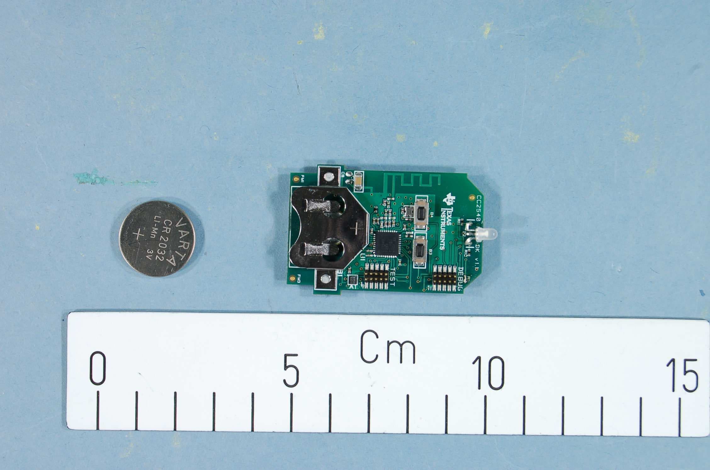
Click to zoom
Application Details
- Equipment Class
- DTS - Digital Transmission System
- Date of Grant
- Nov 28, 2012
- Application Purpose
- Original Equipment
- Date of Application
- Nov 28, 2012
- Equipment Note
- The CC2540KEYFOB is a development tool for the 2.4 GHz CC2540 BLE System-on-Chip with USB from TI.
- Frequency Range
- 2402.00000000 - 2480.00000000
- Company
- Texas Instruments Inc.
- Country
- United States
Documents & Files
Document Text
Text extracted from the exhibit documents filed with the FCC. Open a document above to read the original.
Users Manual
SWRU3XX December 2012 Web sites: www.ti.com/ble E2E Forum: www.ti.com/ble-forum CC2540 Mini Development Kit Quick Start Guide Opening the Box and Evaluating Bluetooth® Low Energy Kit Contents 1 x CC2540 USB dongle 1 x CC2540 Keyfob board 1 x Keyfob plastic case 1 x CC Debugger with cables 1 x CR2032 Battery Documentation The RF Boards in this kit are FCC and IC certified and tested to comply with ETSI/R&TTE over temperature from 0 to +35°C. Caution! The kit contains ESD sensitive components. Handle with care to prevent permanent damage. Introduction This document will guide you through the initial steps required in order to run the pre programmed Bluetooth® low energy demo application. You will get familiar with the hardware in the box and some of the tools that can be used for developing your own software at a later stage. For the CC2540DK-MINI, there are two ways of getting started: 1. Evaluate Using BTool. BTool is a Windows application that allows you to control a central device using the serial interface and perform various BLE functions while connected to a peripheral device, such as the CC2540 Keyfob. 2. Evaluate Using iPhone 4S/5. Apple iPhone 4S and 5 both support BT4.0 and Texas Instruments have created an iOS Application to evaluate a peripheral device, such as the CC2540 Keyfob. Hardware Setup First, you will need to power up the CC2540 Keyfob. When you insert the CR 2032 battery, the LED will be lit green for one second. You can toggle Advertisements on and off by pushing the right button on the CC2540 Keyfob. During advertisement, the LED will be blinking red. Caution! This kit includes a non-rechargeable lithium battery. Always make sure the battery is removed from the CC2540 Keyfob when it is connected to an external power source (Do not apply voltage > 3.6V). Dispose the battery properly and keep out of the reach of children. If swallowed, contact a physician immediately. Evaluate Using BTool 1. Download & Install BLE-Stack The latest BLE software can be downloaded at www.ti.com/ble-stack. After the BLE-Stack software installation is complete, the USB Dongle driver must be associated with the device in order to use the BTool application. To associate the USB Dongle driver, you must first connect the USB Dongle to the PC’s USB port, or to a USB hub that connects to the PC The first time that the dongle is connected to the PC, a message will pop-up, indicating that Windows does not recognize the device. The driver is found in the folder Accessories\ Drivers in the default install directory. For more information on how to install the driver, please refer to the CC254XDK-MINI User Guide, found at... 2. Identify the COM Port Number Once the driver is installed, you need to determine which COM port Windows has assigned to the USB Dongle. Right-click on “Computer”, listed in the Start Menu, and select “Properties”. The “System Properties” window should open up, where you can select “Device Manager”. A list of all hardware devices should appear. Under the section “Ports (COM & LPT)”, the device “TI CC2540 Low-Power RF to USB CDC Serial Port” should appear. Next to the name should be the port number (COM#) Take note of this port number, as it will be needed in order to use BTool. 3. Start BTool BTool is included as part of the installation of the BLE stack and can be found in the folder \Projects\BTool in the default install directory. When you start up BTool, you will be prompted to set port settings. Select the options below and press “OK”. 4. Connect to CC2540 Keyfob Pressing the right button on the CC2540 Keyfob starts the advertisement. The device advertises for 30 seconds. In BTool, press SCAN button: After the scanning is complete, choose the device to connect to and press “Establish”. 5. Button Notifications To notify when buttons are presses on the CC2540 Keyfob, notifications need to be enabled. This is done in the “Read/Write” Tab of BTool. Simply write 01:00 to character handle 0x0048. If a button on the CC2540 Keyfob is now pushed, notifications will be sent and can be monitored in the BTool log window. 6. Enable Accelerometer Similar to the button notifications, the notifications for the accelerometer data can be enabled. In this example we will only enable notifications for the x-axis. First of all, the accelerometer need to be enabled, which is done by writing 01:00 to character handle 0x0034 in the “Read/Write” tab of BTool. To enable notifications for the x-axis, write 01:00 to character handle 0x003B. This will enable the CC2540 Keyfob to send notifications as you move it. 7. Immediate Alert To sound the buzzer located on the CC2540 Keyfob, write the following value to handle 0x0028: 01:00 for low Alert 02:00 for high Alert 00:00 to turn off. The buzzer will sound for 10 seconds. 8. Terminate Connection To terminate the connection you will have three options: Remove the battery from the CC2540 Keyfob, which will trigger a supervision timeout. Move the CC2540 Keyfob out of range (typically >10m), which will trigger a supervision timeout. Press the “Terminate” button in BTool as indicated in the image below. 9. Source Code The project and source code files for the pre programmed application (as well as many others) are included with the Bluetooth low energy (BLE) stack from Texas Instruments, which can be downloaded at www.ti.com/ble-stack. The project implementing this demo is called Keyfobdemo (CC2540 Slave configuration). The project can be modified as desired, and should provide a good framework for developing your own custom BLE applications. More details on these projects can be found within the BLE Software Developer’s Guide, which is included with the stack. For troubleshooting please refer to the CC254XDK-MINI User Guide, found at... Evaluate Using iPhone 4S/5 1. Download the Application The iPhone 4S/5 app can be downloaded via iTunes (found at www.apple.com/itunes) or App Store which are pre installed on the iPhone 4S/5. !! This…
Text truncated - open the document above for the full version.
Block Diagram
CC2540Keyfob CC2540 f = <2400MHz – 2480MHz> CTRL LNA PA FREQUENCY SYNTHESIZER f_internal = <4800MHz – 4960MHz> f_output = <2400MHz – 2480MHz> AAF LPF ADC ADC DAC DAC DEMODULATOR MODULATOR RADIO CONTROLLER AND DATA INTERFACE QI QI RF_N RF_P I Q I Q CLOCK MUX P 2 _ 4 P 2 _ 3 X O S C _ Q 2 X O S C _ Q 1 16MHz RC-OSC 32kHz RC-OSC 32MHZ Crystal OSC 32.768kHz Crystal OSC BALUN ADC CLOCK
Cover Letter(s)
June 4, 2012 Nemko Canada Inc 303 River Road Ottawa, Ontario, Canada K1V 1H2 Attn: Director of Certification Authority to Act as Agent FCC On our behalf, I appoint Zarah MacIvor of Nemko USA, Inc. at 802 N Kealy Avenue, Lewisville TX 75057 to act as our agent in the preparation of this application for equipment certification. I certify that submitted documents properly describe the device or system for which equipment certification is sought. I also certify that each unit manufactured, imported or marketed, as defined in FCC regulations will have affixed to it a label identical to that submitted for approval with this application. In signing this letter, Applicant certifies that neither the applicant nor any party to the application is not subject to a denial of Federal benefits, that include FCC benefits, pursuant to Section 5301 of the Anti-Drug Abuse Act of 1988, 21 U.S.C. § 862 because of a conviction for possession or distribution of a controlled substance. See 47 CFR 1.2002(b) for the definition of a "party" for these purposes. For instances where our authorized agent signs the application for certification on our behalf, I acknowledge that all responsibility for complying with the terms and conditions for certification, as specified by Nemko Canada Inc, still resides with Texas Instruments, Inc., 12500 TI Boulevard, Dallas, TX 75243. Dated this 4th Day of June 20 12 Agency agreement expiration date: Usually Give 8 - 12 Months By: Signature Printed Title: On behalf of : (Company Name)
External Photos
Project no.: 215170-5 Page 1 of 2 EXTERNAL PHOTOS – CC2540KEYFOB CC2540KeyFob with a cell coin battery, EUT for radiated measurements
ID Label/Location Info
Certification Document Label 1/1 Description of label for CC2540Keyfob FCC/IC/CE labeling of product is shown below. The FCC ID, IC number and CE logo is printed directly on the PCB. There is a separate label with the model name, revision and serial number. ~ 33 mm ~ 5 0 m m Texas Instruments Model: CC2540Keyfob Rev.: x.x.x S.N.: xxxxxx
Internal Photos
Project no.: 215170-5 Page 1 of 2 INTERNAL PHOTOS – CC2540KEYFOB CC2540KeyFob with a cell coin battery, EUT for radiated measurements Project no.: 215170-5 Page 2 of 2 The battery pack used during testing CC2540KeyFob used for conducted measurements
Operational Description
Texas Instruments Norway AS Gaustadalléen 21 0349 Oslo Norway (+47) 22 95 85 44 (+47) 22 95 85 46 Page 1 of 1 Technical Description The CC2540Keyfob is an evaluation board for the CC2540 chip from Texas Instruments. The CC2540Keyfob is included in a development kit that can be used as for Bluetooth Low Energy development. The CC2540 System on Chip has a differential RF output. On the CC2540Keyfob board this differential output is transformed to a single ended, 50 ohm signal through a discrete balun. Additionally, the balun ha greatly reduces harmonic radiation. The single ended output of the balun is connected to an on-board PCB antenna.
Parts List/Tune Up Info
CC2540 Keyfob Partlist List 1.2.0 Ref. Part name Pcs/unit Description Manufacturer Part number Supplier Ordering code U1 CC2540 1 2.4 GHz SoC TI CC2540 TI CC2540 A1 CMA3000-D01 1 3-axis ultra low power accelerometer with digital S PI and I2C interface VTI Technologies CMA3000-D01 EG Components CMA3000-D01 B1 CR2032_SOCKET 1 Socket for CR2032 buttoncell battery K eystone 3002 ELFA 69-525-27 C9 C_0805 1 Capacitor, general, 0805; Do not mount C2;C101;C211;C241;C281;C291;C311 C_100N_0402_X5R_K_1 0 7 Capacitor, 100n, 0402, X5R, 10%, 10V Murata GRM155R71A104KA01D C221;C231 C_12P_0402_NP0_J_50 2 Capacitor, 12p, 0402, NP0, 5%, 50V Murata GRM1555C1H120JZ01D C321;C331 C_15P_0402_NP0_J_50 2 Capacitor, 15p, 0402, NP0, 5%, 50V Murata GRM1555C1H150JZ01D C251;C261 C_18P_0402_NP0_J_50 2 Capacitor, 18p, 0402, NP0, 5% 25V Murata GRM1555C1H180JZ01D ELFA 65-881-23 C8 C_1N_0402_NP0_J_50 1 Capacitor, 1n, 0402, NP0, 5%, 50 V Murata GRM1555C1H102JA01D C252-253;C262 C_1P0_0402_NP0_C_50 3 Capacitor, 1p, 040 2, NP0, +/-0.25pF 50V Murata GRM1555C1H1R0CZ01D C391;C401 C_1U_0402_X5R_K_6P3 2 Capacitor, 1u, 0402, X 5R, 10%, 6.3V Murata GRM155R60J105KE19D C271 C_220P_0402_NP0_J_50 1 Capacitor, 220p, 0402, NP0, 5% , 50V Murata GRM1555C1H221JA01D C7 C_47U_1206_X5R_K_6P3 1 Capacitor, 47u,1206, X5R, 10%, 6.3V Murata GRM31CR60J476KE19L D2 LED_EL209EGW 1 LED, red/green, 3.0mm, 2/2.1V, 10/3,6 mcd Everlight 209SURSYGW/S530-A3 ELFA 75-010-26 L252 L_1N0_0402_S 1 Inductor, 1n0, 0402, Monolithic type, +/-0.3 nH Murata LQG15HS1N0S02D L251;L261 L_2N0_0402_S 2 Inductor, 2n0, 0402, +/-0.3 n H Murata LQG15HS2N0S02D L253 L_3N0_0402_S 1 Inductor, 3n0, 0402, Monolithic type, +/-0.3 nH Murata LQG15HS3N0S02D ACTE B2 CMT-1603 1 Piezo audio transducer, 25V, SMD CUI Inc. CMT-1603 Digikey 102-1193-1-ND R1 R_0402 1 Resistor, general, 0402; Do not mount R11-12 R_270_0402_F 2 Resistor, 270 ohms, 0402, ±1% K oa RK73H1E270RF-MR or RK73H1ETTP2700F ELFA 60-885-61 or 60-477-73 R2 R_2K7_0402_F 1 Resistor, 2k7 ohms, 0402, ±1% Koa RK73H1ETTP2701F ELFA 60-482-50 R301 R_56K_0402_F 1 Resistor, 56k ohms, 0402, ±1% Koa RK73H1ETTP5602F ELFA 60-488-96 DEBUG;TEST STL21 2 10 pins connector MPE-Garry GmbH STL21-A01XX-010-TRU Freber B3-4 147873-2 2 SMD 2 pin button switch Tyco Electronics 147 873-2 X1 X_32.000/10/20/60/10 1 Crystal, 32 MHz, FA-128 -40/+ 85C, 10pF, Epson Toyocom FA-128, 32MHZ, 10PPM, 10PF, 2x1.6mm, -40/+85C, ACTE Q22FA1280009200 X2 X_32.768/20/50/40/12 1 Crystal, 32.768 kHz, 12.5pF, 20/50 ppm,SMD package Epson Toyocom MC-306 ACTE Q13MC3061000314 Total no of components 42
RF Exposure Info
Prediction of MPE limit at a given distance Equation from page 18 of OET Bulletin 65, Edition 97-01 where:S = power density P = power input to the antenna G = power gain of the antenna in the direction of interest relative to an isotropic radiator R = distance to the center of radiation of the antenna Maximum peak output power at antenna input terminal:1.8(dBm)* Maximum peak output power at antenna input terminal:1.5(mW) Antenna gain(maximum):-1.5(dBi)* Maximum antenna gain:0.71(numeric) Time Averaging:100(%)* Prediction distance:20(cm)* Prediction frequency:2450(MHz)* MPE limit for uncontrolled exposure at prediction frequency:1.000(mW/cm^2) Power density at prediction frequency:0.0002 (mW/cm^2) This equates to:0.002 W/m^2 2 4R PG S
Test Report
Nemko AS, Gaustadalléen 30, P.O.Box 73 Blindern, NO-0314 Oslo Norway T +47 22 96 03 30 F +47 22 96 05 50 Enterprise number NO974404532 Visiting address: Nemko Kjeller, Instituttveien 6, P.O.Box 96, NO-2027 Kjeller Norway T +47 64 84 57 00 F +47 64 84 57 05 Test report no. : 215170- 3 Item tested : CC2540KEYFOB Type of equipment : 2.4 GHz Transceiver FCC ID : ZAT2540KEYFOB Client : Texas Instruments Norway AS FCC Part 15.247 Digital Transmission System RSS-210, Issue 8 Low Power Licence-Exempt Radiocommunication Devices 19 October 2012 Authorized by : .............................................. Frode Sveinsen Technical Verificator TEST REPORT FCC part 15.247 Ref. no.: 215170-3 FCC ID: ZAT2540KEYFOB IC ID: 451H-2540KEYFOB Nemko AS, NO-2027 Kjeller Page 2 (44) CONTENTS 1 GENERAL INFORMATION ...................................................................................................... 3 1.1 Testhouse Info .......................................................................................................................... 3 1.2 Client Information ...................................................................................................................... 3 1.3 Responsible Manufacturer (If other than client) ........................................................................ 3 2 Test Information ...................................................................................................................... 4 2.1 Test Item ................................................................................................................................... 4 2.2 Test Environment ...................................................................................................................... 5 2.3 Test Period................................................................................................................................ 5 3 TEST REPORT SUMMARY ..................................................................................................... 6 3.1 General ..................................................................................................................................... 6 3.2 Test Summary ........................................................................................................................... 7 3.3 Description of modification for Modification Filing ..................................................................... 7 3.4 Comments ................................................................................................................................ 7 3.5 Family List Rational .................................................................................................................. 7 4 TEST RESULTS ....................................................................................................................... 8 4.1 Power Line Conducted Emissions ............................................................................................ 8 4.2 Minimum 6 dB Bandwidth ......................................................................................................... 9 4.3 20 dB Bandwidth ..................................................................................................................... 13 4.4 Peak Power Output ................................................................................................................. 15 4.5 Spurious Emissions (Radiated) .............................................................................................. 22 4.6 Power Spectral Density (PSD) ................................................................................................ 39 5 LIST OF TEST EQUIPMENT .................................................................................................. 43 6 BLOCK DIAGRAM ................................................................................................................. 44 6.1 Power Line Conducted Emission ............................................................................................ 44 6.2 Test Site Radiated Emission ................................................................................................... 44 TEST REPORT FCC part 15.247 Ref. no.: 215170-3 FCC ID: ZAT2540KEYFOB IC ID: 451H-2540KEYFOB Nemko AS, NO-2027 Kjeller Page 3 (44) 1 GENERAL INFORMATION 1.1 Testhouse Info Name : Nemko AS Address : Nemko Kjeller Instituttveien 6, Box 96 NO-2027 Kjeller, NORWAY Telephone : +47 64 84 57 00 Fax : +47 64 84 57 05 E-mail: [email protected] FCC test firm : 994405 IC OATS : 2040D-1 Total Number of Pages: 44 1.2 Client Information Name : Texas Instruments Norway AS Address : Gaustadalléen 21, NO-0349 Oslo, Norway Telephone : +47 22 95 85 44 Fax : +47 22 95 85 46 Contact: Name : Dag Grini Telephone : +47 22 95 83 01 E-mail : [email protected] 1.3 Responsible Manufacturer (If other than client) Same as the client TEST REPORT FCC part 15.247 Ref. no.: 215170-3 FCC ID: ZAT2540KEYFOB IC ID: 451H-2540KEYFOB Nemko AS, NO-2027 Kjeller Page 4 (44) 2 Test Information 2.1 Test Item Name : Texas Instruments FCC ID : ZAT2540KEYFOB IC : 451H-2540KEYFOB Model/version : CC2540KEYFOB Serial number : 0000 1243 (with PCB antenna) 0000 1293 (with SMA connector) Hardware identity and/or version: / Software identity and/or version : / Frequency Range : 2402 – 2480 MHz Number of Channels : 40 Type of Modulation : GFSK Output power: 1.5 mW (Conducted) Data rate: 1000kbps User Frequency Adjustment : None Type of Power Supply : 3.0 V DC (one CR2032 cell battery) Antenna Connector : PCB antenna Antenna Diversity Supported : No Desktop Charger : None Description of Test Item The CC2540KEYFOB supports the Bluetooth Low Energy (BLE) standard, which is considered Digital Modulation per FCC part 15.247a. Exposure Evaluation The EUT is exempted from RF Exposure Evaluation. TEST REPORT FCC part 15.247 Ref. no.: 215170-3 FCC ID: ZAT2540KEYFOB IC ID: 451H-2540KEYFOB Nemko AS, NO-2027 Kjeller Page 5 (44) 2.2 Test Envi…
Text truncated - open the document above for the full version.
Test Setup Photos
Project no.: 215170-4 Page 1 of 3 PHOTOS OF TEST SET-UP – CC2540KEYFOB XZ plane - Radiated Emissions YZ plane - Radiated Emissions Project no.: 215170-4 Page 2 of 3 Radiated emissions - < 30MHz Radiated Emissions 30 - 1000MHz Project no.: 215170-4 Page 3 of 3 Radiated emissions 1 – 12 GHz Radiated Emissions 12 - 18 GHz
Contact Information
Applicant
Marian Kost(Product Line Manager, Connectivity)
Technical Contact
Non-Technical Contact
Nemko USA, Inc.Zarah G MacIvor
[email protected]214-629-5683
Test Firm
Nemko ASFrode Sveinsen
Technical Specifications
| # | Rule Parts | Frequency Range | Power Output |
|---|---|---|---|
| 1 | 15C | 2.40 GHz - 2.48 GHz | 1.50 mW |
Other Applications from Texas Instruments Inc.
ZAT-2340R5MODA
Jan 30, 2026CC2340R5MODAN0MHAR
Equipment Class
DTS - Digital Transmission SystemZAT-1312PSIP-3
May 19, 2024CC1312PSIP
Equipment Class
DSS - Part 15 Spread Spectrum TransmitterZAT-1312PSIP-2
Jan 21, 2024CC1312PSIP
Equipment Class
DSS - Part 15 Spread Spectrum Transmitter
ZAT-1312PSIP-1
Jul 09, 2023CC1312PSIP
Equipment Class
DSS - Part 15 Spread Spectrum Transmitter
ZAT7IDEM
Feb 27, 2014The 7IDEM is a development tool for TIs 2.4 GHz 7ID System-on-Chip
Equipment Class
DTS - Digital Transmission System