ZAT2541ARCThe CC2541ARC is a development tool for the 2.4 GHz CC2541 BLE System-on-Chip from TI
Texas Instruments Inc.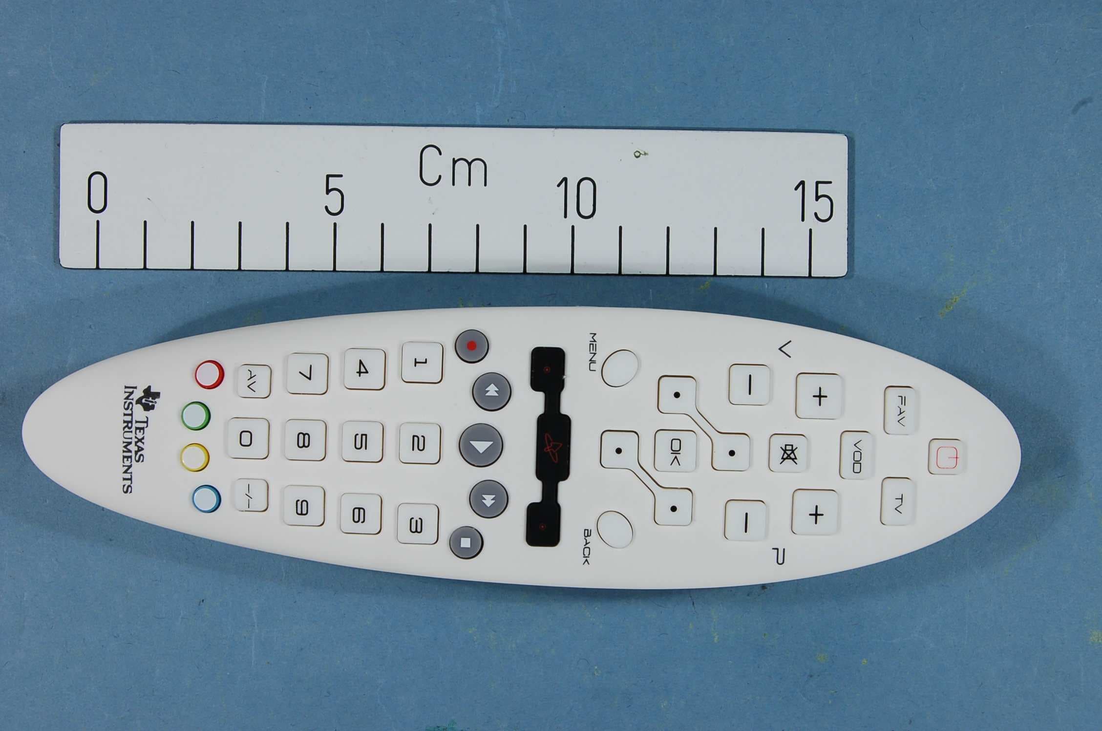
Click to zoom
Application Details
- Equipment Class
- DTS - Digital Transmission System
- Date of Grant
- Jan 29, 2013
- Application Purpose
- Original Equipment
- Date of Application
- Jan 28, 2013
- Equipment Note
- The CC2541ARC is a development tool for the 2.4 GHz CC2541 BLE System-on-Chip from TI
- Frequency Range
- 2402.00000000 - 2480.00000000
- Company
- Texas Instruments Inc.
- Country
- United States
Documents & Files
Document Text
Text extracted from the exhibit documents filed with the FCC. Open a document above to read the original.
Users Manual
SWRU??? January 2013 Web sites: www.ti.com/ble E2E Forum: www.ti.com/ble-forum CC2541 Advanced Remote Control Quick Start Guide Opening the Box and Evaluating Bluetooth® Low Energy Kit Contents 1 x Advanced Remote 1 x CC2540USB Dongle 1 x CC Debugger/Programmer 3 x AAA Battery Documentation The RF Boards in this kit are FCC and IC certified and tested to comply with ETSI/R&TTE over temperature from 0 to +35°C. Caution! The kit contains ESD sensitive components. Handle with care to prevent permanent damage. Introduction This document will guide you through the initial steps required in order to run the pre programmed Bluetooth® low energy (BLE) demo application. You will get familiar with the hardware in the box and how to interface the remote with different platforms. 1. Evaluate using dongle. A USB dongle pre-programmed with firmware acting as translator between BLE HID and USB HID is supplied in the kit and works with most operating system platforms. 2. Evaluate using Windows 8 native. Windows 8 includes native support for the BLE HID over GATT profile. Using a BT4.0 dongle or internal BT4.0 hardware you can easily connect the Advanced Remote to your computer. Hardware Setup Insert 3xAAA (LR03) batteries in the Advanced Remote’s battery holder. You are good to go. Pressing any button on the remote will put it into advertising mode and make it detectable by Bluetooth Low Energy capable hosts. Connect Using Single Mode BT4.0 Low Energy CC2540USB HID Dongle 1. Insert dongle in USB port The dongle will be enumerated as three USB Human Interface Device class devices. Mouse Keyboard Consumer control The LED on the dongle should start blinking red, indicating it’s scanning for a Bluetooth Low Energy peripheral which advertises BLE HID service capabilities. 2. Advertise and connect Press any number key or consumer control key to make the device advertise. The devices will now connect and pair using JustWorks pairing. The dongle LED should now blink green when data is received from the Advanced Remote and otherwise be off. Long term bonding entries will be stored in both the Advanced Remote and dongle to speed up subsequent reconnections. 3. Manage connection and bonds Pressing SW1 on the dongle will disconnect any active connection between the dongle and an Advanced Remote. Pressing SW2 on the dongle will erase all long term bond information stored on the dongle. Pressing this button will not affect bond data stored on the Advanced Remote. Connect to Windows 8 with BT 4.0 LE (Smart Ready) hardware 1. Make sure LE works In Device manager, under Bluetooth, make sure that you see references to Bluetooth LE. 2. Open PC settings Move your mouse to the lower right hand corner and click on Settings. Then click on Change PC settings. 3. Add Advanced Remote Then click on Devices and Add a device. 4. Select and add the remote If you have pressed a button on the Advanced Remote, and it’s not connected to another host, it will show up in the list of found devices. 5. Enter pairing code The devices will now pair using Passkey entry. On your Advanced Remote, enter the 6-digit passkey displayed on the computer screen. The Advanced Remote is now paired with Windows and bond data is stored on both devices, making reconnection faster and passkey entry unnecessary. 6. Remove device A device can be removed from Windows and bond data deleted by clicking on the device and then the ( – ) symbol. Using the Advanced Remote Control Mouse keys Mouse speed Action keys 1. Advertise and connect Almost all the keys will make the Advanced Remote start advertising and be discoverable by hosts scanning for HID capable BLE devices. 2. Keyboard input Pressing any number will act as a keyboard input of that number. The same goes for OK which is Enter, Back which is Backspace and the four keys surrounding OK, which act as directional or arrow keys. 3. Consumer control Buttons such as Volume, Mute, Play/Pause etc. are consumer control keys, and will control media settings on your computer. 4. Mouse input Holding down the middle button will prompt the Advanced Remote to interpret your movement of the remote as mouse input and send this to the computer. Double clicking the middle button will lock the mouse function. The left and right buttons act as left and right mouse buttons. Pressing AV and –/– will decrease and increase mouse speed. 5. Remove bond information Pressing the Red action button will remove bonding information stored on the Advanced Remote. Pairing will have to be done again, using passkey entry if applicable. 6. Calibrate Pressing the Blue action button will force the Advanced Remote to recalibrate the onboard gyroscope and accelerometer used for motion sensing. Additional Tools and Links BLE Packet Sniffer The CC2540 USB Dongle can be used as a BLE sniffer and monitor packets while the iPhone 4S Demo is running. The SmartRF Protocol Packet Sniffer software can be downloaded at www.ti.com/packetsniffer. SmartRF Flash Programmer Texas Instruments has a simple tool which can be used to program and flash the CC2541. SmartRF Flash Programmer can be downloaded at www.ti.com/tool/flash-programmer. IAR Embedded Workbench To develop software, program, and debug the CC2541, you should use IAR Embedded Workbench for 8051. More information on IAR EW8051, including a free evaluation version download, can be found at www.iar.com/ew8051. BLE E2E Forum For additional help, visit the TI Bluetooth low energy E2E forum, www.ti.com/ble-forum, for instant support during your development. BLE Wiki Our BLE Wiki contains application examples, guides and documentation covering those extra steps you might need help with. The Wiki is not only managed by Texas Instruments employees but also E2E community members. Anyone can share, edit and make use of the information posted here. The Wiki is found at www.ti.com/ble-wiki. Useful Links TI BLE Stack and Software: www.ti.com/ble-stack CC2540/41 Mini Development Kit User Guide: www.…
Text truncated - open the document above for the full version.
Block Diagram
CC2541ARC CC2541 f = <2400MHz – 2480MHz> CTRL LNA PA FREQUENCY SYNTHESIZER f_internal = <4800MHz – 4960MHz> f_output = <2400MHz – 2480MHz> AAF LPF ADC ADC DAC DAC DEMODULATOR MODULATOR RADIO CONTROLLER AND DATA INTERFACE QI QI RF_N RF_P I Q I Q CLOCK MUX P 2 _ 4 P 2 _ 3 X O S C _ Q 2 X O S C _ Q 1 16MHz RC-OSC 32kHz RC-OSC 32MHZ Crystal OSC 32.768kHz Crystal OSC BALUN ADC CLOCK
External Photos
PHOTOS of EUT Project no.: 227631 FCC ID: ZAT2541ARC Page 2 of 2 CC2541ARC, External photos
ID Label/Location Info
Certification Document Label 1/1 Description of label for CC2541ARC FCC/IC/CE labeling of product is shown below. The labels are attached to the underside of the remote control enclosure. ~ 5 5 m m ~ 197 mm T e x a s I n s t r u m e n t s M o d e l : C C 2 5 4 1 A R C R e v . : x . x . x S N . : x x x x F C C I D : Z A T 2 5 4 1 A R C I C : 4 5 1 H - 2 5 4 1 A R C
Internal Photos
PHOTOS of EUT Project no.: 227631 FCC ID: ZAT2541ARC Page 1 of 2 INTERNAL PHOTOS – CC2541ARC CC2541ARC, EUT for radiated measurements
Operational Description
Texas Instruments Norway AS Gaustadalléen 21 0349 Oslo Norway (+47) 22 95 85 44 (+47) 22 95 85 46 Page 1 of 1 Technical Description The CC2541ARC is an evaluation board for the CC2541 chip from Texas Instruments. The CC2541ARC is included in a development kit that can be used as for Bluetooth Low Energy development. The CC2541 System on Chip has a differential RF output. On the CC2541ARC board this differential output is transformed to a single ended, 50 ohm signal through a discrete balun. Additionally, the balun ha greatly reduces harmonic radiation. The single ended output of the balun is connected to an on-board PCB antenna.
Parts List/Tune Up Info
Texas Instruments Norway AS Gaustadalléen 21 0349 Oslo Norway (+47) 22 95 85 44 (+47) 22 95 85 46 Page 1 of 1 Tune-up Procedure The CC2541ARC will be pre-programmed with an output power level of 0 dBm.
Parts List/Tune Up Info
Part ReferenceQuantityValuePCB PackageDescriptionMPNManufacturer BAT+1BAT+NON COMPONENT, BATTERY + PAD, SMD BAT-1BAT-NON COMPONENT, BATTERY - PAD, SMD BZR11PS1240P02BTACOUSTIC, BUZZER, UP TO 30V, PTHPS1240P02BTTDK C1,C921uF0402CAPACITOR, CERAMIC X5R, 1uF, 10V, -10%/+10%, -55DEGC/+85DEGC, 0402, SMDGRM155R61A105KE15DMURATA C2-C6,C23,C24,C31-C33,C3511100nF0402CAPACITOR, CERAMIC X7R, 100nF, 10V, -10%/+10%, -55DEGC/+125DEGC, 0402, SMDGRM155R71A104KA01DMURATA C71220pF0402CAPACITOR, CERAMIC C0G/NP0, 220pF, 50V, -5%/+5%, -55DEGC/+125DEGC, 0402, SMDGRM1555C1H221JA01DMURATA C10,C30,C3432.2uF0402CAPACITOR, CERAMIC X5R, 2.2uF, 6.3V, -20%/+20%, -55DEGC/+85DEGC, 0402, SMDGRM155R60J225ME95DMURATA C11,C12215pF0402CAPACITOR, CERAMIC C0G/NP0, 15pF, 50V, -5%/+5%, -55DEGC/+125DEGC, 0402, SMDGRM1555C1H150JA01DMURATA C15,C18,C38,C39418pF0402CAPACITOR, CERAMIC C0G/NPO, 18pF, 50V, -55DEGC/+125DEGC, 0402, SMDGRM1555C1H180JA01DMURATA C19-C2131pF0402CAPACITOR, CERAMIC C0G/NP0, 1pF, 50V, -0.1pF/+0.1pF, -55DEGC/+125DEGC, 0402, SMDGRM1555C1H1R0BA01DMURATA C221100uFRADIALCAPACITOR, ALUMINUM, 100uF, 10V, -20%/+20%, -40DEGC/+85DEGC, RADIAL, SMDEEE1AA101WRPANASONIC INDUSTRIAL C29,C41215nF0402CAPACITOR, CERAMIC X7R, 15nF, 16V, -5%/+5%, -55DEGC/+125DEGC, 0402, SMDCAPACITOR_0402_15nF_X7R_M_+/-5%_16VManufacturer selection C36110nF0402CAPACITOR, CERAMIC X7R, 10nF, 25V, -10%/+10%, -55DEGC/+125DEGC, 0402, SMDGRM155R71E103KA01DMURATA C3712.2nF0402CAPACITOR, CERAMIC X7R, 2.2nF, 50V, -10%/+10%, -55DEGC/+125DEGC, 0402, SMDGRM155R71H222KA01DMURATA C4011nF0402CAPACITOR, CERAMIC X7R, 1nF, 50V, -10%/+10%, -55DEGC/+125DEGC, 0402, SMDCAPACITOR_0402_1nF_X7R_M_+/-10%_50VManufacturer selection D11IR333-AOPTO, LED, IR, 940nm, 0.1A, 0.15W, PTHOPE5594AKNOWLEDGE-ON FB1-FB55BLM15HG102SN10402FILTER, INDUCTOR TYPE, 1000OHM@100MHZ, 25%,250mA, 0402, SMDBLM15HG102SN1DMURATA L1,L322nH0402INDUCTOR, CHIP, 2nH, -0.3nH/ +0.3nH, 0.3A, -55DEGC/+125DEGC, 0402, SMDLQG15HS2N0S02DMURATA L211nH0402INDUCTOR, CHIP, 1nH, -0.3nH/+0.3nH, 0.3A, -55DEGC/+125DEGC, 0402, SMDLQG15HS1N0S02DMURATA L413nH0402INDUCTOR, CHIP, 3nH, -0.3nH, +0.3nH, 0.3A, -55DEGC/+125DEGC, 0402, SMDLQG15HS3N0S02DMURATA P11FTSH-105-01-F-DV-KCONNECTOR, HEADER, MALE, STRAIGHT, 10 PINS, 2 ROWS, PITCH 1.27mm, SMDFTSH-105-01-F-DV-KSAMTEC Q3,Q42BC817-16SOT23-3TRANSISTOR, BIPOLAR NPN, 45V, 0.5A, 0.25W, SOT23-3, SMDBC817-16,215NXP Q512N7002SOT23-3TRANSISTOR, MOSFET N-CHANNEL, 60V, 0.3A, 0.83W, SOT23-3, SMD2N7002,215NXP R1156k0402RESISTOR, THICK FILM, 56k, -1%/+1%, 0.063W, 50V, -55DEGC/+155DEGC, 0402, SMDRESISTOR_0402_56k_+/-1%_50V_0.063W_M_+/-100PPMManufacturer selection R2,R92DNMRESISTOR, DO NOT MOUNT, 0402, SMD R31301210RESISTOR, THICK FILM, 30, -5%/+5%, 0.33W, 200V, -55DEGC/+125DEGC, 1210, SMDCRCW121030R0JNEAVISHAY DALE R412200402RESISTOR, THICK FILM, 220, -1%/+1%, 0.1W, 50V, -55DEGC/+155DEGC, 0402, SMDERJ2RKF2200XPANASONIC INDUSTRIAL R5,R1022.2k0402RESISTOR, THICK FILM, 2.2k, -1%/+1%, 0.1W, 50V, -55DEGC/+155DEGC, 0402, SMDERJ2RKF2201XPANASONIC INDUSTRIAL R6,R1821k0402RESISTOR, THICK FILM, 1k, -1%/+1%, 0.1W, 50V, -55DEGC/+155DEGC, 0402, SMDERJ2RKF1001XPANASONIC INDUSTRIAL R71DNMRESISTOR, DO NOT MOUNT, 0603, SMD R8,R12,R24300402RESISTOR, THICK FILM, 0, 0.1W, 50V, -55DEGC/+155DEGC, 0402, SMDERJ2GE0R00XPANASONIC INDUSTRIAL R11100402RESISTOR, JUMPER, 3 PORTS, -55DEGC/+155DEGC, 0402, SMDRK73Z1ETTPKOA SPEER R13,R202DNM0402RESISTOR, DO NOT MOUNT, 0402, SMDDNMDO NOT MOUNT R14-R1742.2kRESISTOR NETWORK, CHIP ARRAY – 4 RESISTORS, 2.2k, -5%/+5%, 0.031W, 50V, -55DEGC/+155DEGC, SMDEXBN8V222JXPANASONIC INDUSTRIAL R1912k0402RESISTOR, THICK FILM, 2k, -1%/+1%, 0.1W, 50V, -55DEGC/+155DEGC, 0402, SMDERJ2RKF2001XPANASONIC INDUSTRIAL R2112.7k0402RESISTOR, THICK FILM, 2.7k, -1%/+1%, 0.063W, 50V, -55DEGC/+155DEGC, 0402, SMDRESISTOR_0402_2.7k_+/-1%_50V_0.063W_M_+/-100PPMManufacturer selection R22115k0402RESISTOR, THICK FILM, 15k, -1%/+1%, 0.063W, 50V, -55DEGC/+155DEGC, 0402, SMDRESISTOR_0402_15k_+/-1%_50V_0.063W_M_+/-100PPMManufacturer selection R23147k0402RESISTOR, THICK FILM, 47k, -1%/+1%, 0.063W, 50V, -55DEGC/+155DEGC, 0402, SMDRESISTOR_0402_47k_+/-1%_50V_0.063W_M_+/-100PPMManufacturer selection TP1,TP4-TP86TP_0.5MM_PTHTESTPOINT, 0.5MM HOLE, PTH U11CC2541F256VQFN40IC, DIGITAL WIRELESS, 2.4-GHz BLUETOOTH® LOW ENERGY AND PRIOPRIETARY SYSTEM-ON-CHIP, 256 KB, 2V TO 3.6V, VQFN40, SMDCC2541F256RHARTEXAS INSTRUMENTS U21KXTF9LGA10IC, TRANSDUCER, TRI-AXIS DIGITAL ACCELEROMETER, 1.8V TO 3.6V, LGA10, SMDKXTF9-2050KIONIX U4,U62SN74LV164ATSSOP14IC, DIGITAL, LOGIC, 8 BIT PARALLEL OUT SERIAL SHIFT REGISTER, 2V TO 5.5V, TSSOP14, SMDSN74LV164APWRTEXAS INSTRUMENTS U5,U72TPS78330SOT5IC, ANALOG, ULTRA-LOW QUIESCENT CURRENT LOW-DROPOUT LINEAR REGULATOR, 2.2V TO 5.5V, SOT5, SMDTPS78330DDCTTEXAS INSTRUMENTS U81IMU-3000QFN24IC, GYROSCOPE, 2.1V TO 3.6V, QFN24, SMDIMU-3000INVENSENSE Y1132MHzSMDCRYSTAL, OSCILATOR, 32MHz, 10pF, -10PPM/+10PPM, -40DEGC/+85DEGC, SMDFA-128 32MHz 10pF 10PPMEpson Toyocom Y2132.768kHzCRYSTAL, OSCILATOR, 32.768kHz, -20PPM/ + 20PPM, -40DEGC/ +85DEGC, 12.5pF, SMDFC-12M 32.768kHz 20ppmEpson Toyocom
Schematics
11 22 33 44 55 A A B B C C D D Pin 27, 28 & 29 Pin 31 Pin 24 Pin 21 Pin 39 Place close to Vdd pins:Pin 10 IR LED BUZZER BATTERY MONITOR 3.3 V LDO 3.3 V LDO FOR GYRO CC2541 Decoupling Capacitors Place C22 close to D1 DEBUGHEADER R2 and R9 should be connected as triport.For compatibility with other accelerometers. P2.0SCLSDAP1.5P1.7 BuzzerIR_out P1.2P1.3P1.4KPb0KPb1KPb2P0.3P0.4P0.5P0.6P0.7 XOSC32K_Q2XOSC32K_Q1Debug DataDebug Clk P0.7 P0.5 SCLSDA P1.3AUX_DAAUX_CL P1.2 KPa0 KPb2KPb1 KPa0 KPb2KPb1 KPa1 KPb0 KPa7 KPb1 KPa7 KPb2 KPa7 KPb0 KPa6 KPb1 KPa6 KPb2 KPa3 KPb0KPb1 KPa3 KPb2 KPa3 KPb0 KPa2 KPb1 KPa2 KPb2 KPa2 KPb0 KPa5 KPb1 KPa5 KPb2 KPa5 KPb0 KPa8 KPa4 KPb0KPb1 KPa8 KPb2 KPa4 KPb2 KPa8 KPb0 KPa9 KPb1 KPa9 KPb2 KPa9 KPb0 KPa14 KPb1 KPa14 KPb2 KPa14 KPa13 KPb0KPb1 KPa13 KPb2 KPa13 KPb0 KPa10 KPb1 KPa10 KPb2 KPa10 KPb0 KPa12 KPb1 KPa12 KPb1 KPa11 KPb2 KPa11 P0.4 KPa2KPa3KPa4KPa5KPa6KPa7KPa1KPa0 P1.4P0.3P0.3 KPa11KPa10KPa9KPa8KPa12KPa13KPa14KPa15 Debug Data Debug ClkRst_N KPa6KPa1 SCLSDA Rst_N P1.5 P0.6 Buzzer IR_out P1.6 P1.6 +4.5V VDD +4.5V VDD VDD VDD +4.5V Vgyro Vgyro Vgyro VDD +4.5V +4.5V VDD VDD_RF VDD_RF +4.5V Title:Drawn:Checked:Size: Rev: Sheet: of Date: CC2541ARC 1 1 2.1.0 A3 FGKNN Tuesday, December 04, 2012 Title:Drawn:Checked:Size: Rev: Sheet: of Date: CC2541ARC 1 1 2.1.0 A3 FGKNN Tuesday, December 04, 2012 Title:Drawn:Checked:Size: Rev: Sheet: of Date: CC2541ARC 1 1 2.1.0 A3 FGKNN Tuesday, December 04, 2012 VOD KP4 1 2 RED KP37 1 2 R330 R8 0 C1215pF RECORD KP20 1 2 R15 2.2k 234 5678 1 C33100nF C211pF Q4BC817-16 1 32 Y2 32.768kHz 1 2 TV KP3 1 2 -/-- KP36 1 2 C30 2.2uF + C22100uF 12 C1115pF MUTE KP6 1 2 C372.2nF C2100nF MOUSE RIGHT KP19 1 2 C20 1pF VOL DOW N KP8 1 2 C191pF 0 KP35 1 2 C9 1uF VOL UP KP5 1 2 MOUSE MIDDLE KP18 1 2 CH UP KP7 1 2 IMU-3000U8 CLKIN 1 AD0 9 RESV-G 11 GND 18 RESV_19 19 CPOUT 20 RESV_21 21 SCL 23 SDA 24 AUX_DA 6 AUX_CL 7 VLOGIC 8 REGOUT 10 INT 12 VDD 13 CLKOUT 22 NC_14 14 NC_15 15 NC_16 16 NC_17 17 NC_2 2 NC_3 3 NC_4 4 NC_5 5 C18 18pF FIDU1 CH DOW N KP10 1 2 AV KP34 1 2 Q3BC817-16 1 32 C1 1uF MOUSE LEFT KP17 1 2 C40 1nF BACK KP16 1 2 R212.7k R52.2k C15 18pF R2347k C10 2.2uF TP8TP_0.5MM_PTH NAV UP KP9 1 2 9 KP33 1 2 FB1 BLM15HG102SN1 1 2 TPS78330U5 IN 1 GND 2 EN 3 GND 4 OUT 5 R2215k R156k R17 2.2k 234 5678 1 R7 DNM NAV DOW N KP15 1 2 C24100nF R102.2k C38 18pF 8 KP32 1 2 C6100nF FIDU3 FB4 BLM15HG102SN1 12 KXTF9U2 IOVDD 1 NC_2 2 SCL 9 SDA 10 INT 7 NC_6 6 GND 4 NC_3 3 NC_8 8 VDD 5 L1 2nH MENU KP14 1 2 FB5 BLM15HG102SN1 12 R14 2.2k 234 5678 1 7 KP31 1 2 C3100nF 6 KP30 1 2 NAV RIGHT KP13 1 2 R9DNM TP6 TP_0.5MM_PTH POW ER KP1 1 2 L43nH D1IR333-A 12 SN74LV164AU6 A 1 B 2 GND 7 CLK 8 nCLR 9 QA 3 QB 4 QC 5 QD 6 QE 10 QF 11 QG 12 QH 13 VCC 14 C4100nF C3610nF R19 2k 5 KP29 1 2 OK KP12 1 2 CC2541F256U1 nRESET 20 XOSC_Q1 22 XOSC_Q2 23 SCL 2 SDA 3 RF_P 25 RF_N 26 RBIAS 30 NC1 1 GND/EGP 41 AVDD1 28 AVDD2 27 AVDD3 24 AVDD4 29 AVDD5 21 AVDD6 31 DVDD1 39 DVDD2 10 DCOUPL 40 NC4 4 P0_0 19 P0_1 18 P0_2 17 P0_3 16 P0_4 15 P0_5 14 P0_6 13 P0_7 12 P1_0 11 P1_1 9 P1_2 8 P1_3 7 P1_4 6 P1_5 5 P2_0 36 P2_1 35 P2_2 34 P2_3/XOSC32K_Q2 33 P2_4/XOSC32K_Q1 32 P1_6 38 P1_7 37 C29 15nF TP1TP_0.5MM_PTH R2DNM FB3 BLM15HG102SN1 1 2 4 KP28 1 2 NAV LEFT KP11 1 2 C35 100nF R11 0 12 3 C32 100nF Y132MHz 1 2 4 3 C3918pF 3 KP27 1 2 C5100nF 2 KP26 1 2 R16 2.2k 234 5678 1 A1 2.4GHz 3 21 R4 220 + - BZR1 PS1240P02BT 21 - BAT- 1 KP25 1 2 C23100nF C41 15nF FIDU2 STOP KP24 1 2 L21nH C31100nF TP4 TP_0.5MM_PTH FB2 BLM15HG102SN1 1 2 + BAT+ Q52N7002 1 32 R61k TP5 TP_0.5MM_PTH BLUE KP40 1 2 FFW D KP23 1 2 SN74LV164AU4 A 1 B 2 GND 7 CLK 8 nCLR 9 QA 3 QB 4 QC 5 QD 6 QE 10 QF 11 QG 12 QH 13 VCC 14 P1 FTSH-105-01-F-DV-K 2468 13579 10 TP7 TP_0.5MM_PTH R20 DNM R240 R13 DNM C7220pF YELLOW KP39 1 2 PLAY KP22 1 2 R12 0 FAV KP2 1 2 L32nH TPS78330U7 IN 1 GND 2 EN 3 GND 4 OUT 5 C34 2.2uF LBL1TI_LOGO R18 1k GREEN KP38 1 2 REV KP21 1 2
Test Report
Nemko AS, Gaustadalléen 30, P.O.Box 73 Blindern, NO-0314 Oslo Norway T +47 22 96 03 30 F +47 22 96 05 50 Enterprise number NO974404532 Visiting address: Nemko Kjeller, Instituttveien 6, P.O.Box 96, NO-2027 Kjeller Norway T +47 64 84 57 00 F +47 64 84 57 05 Test report no. : 227631- 3 Item tested : CC2541ARC Type of equipment : 2.4 GHz Transceiver FCC ID : ZAT2541ARC Client : Texas Instruments Norway AS FCC Part 15.247 Digital Transmission System RSS-210, Issue 8 Low Power Licence-Exempt Radiocommunication Devices 28 January 2013 Authorized by : .............................................. Frode Sveinsen Technical Verificator TEST REPORT FCC part 15.247 Ref. no.: 227631-3 FCC ID: ZAT2541ARC IC: 451H-2541ARC Nemko AS, NO-2027 Kjeller Page 2 (60) CONTENTS 1 GENERAL INFORMATION ...................................................................................................... 3 1.1 Testhouse Info .......................................................................................................................... 3 1.2 Client Information ...................................................................................................................... 3 1.3 Responsible Manufacturer (If other than client) ........................................................................ 3 2 TEST INFORMATION ............................................................................................................... 4 2.1 Test Item ................................................................................................................................... 4 2.2 Test Environment ...................................................................................................................... 5 2.3 Test Period................................................................................................................................ 5 3 TEST REPORT SUMMARY ..................................................................................................... 6 3.1 General ..................................................................................................................................... 6 3.2 Test Summary ........................................................................................................................... 7 3.3 Description of modification for Modification Filing ..................................................................... 7 3.4 Comments ................................................................................................................................ 7 3.5 Family List Rational .................................................................................................................. 7 4 TEST RESULTS ....................................................................................................................... 8 4.1 Power Line Conducted Emissions ............................................................................................ 8 4.2 Minimum 6 dB Bandwidth ......................................................................................................... 9 4.3 20 dB Bandwidth ..................................................................................................................... 11 4.4 Peak Power Output ................................................................................................................. 13 4.5 Spurious Emissions (Radiated) .............................................................................................. 20 4.6 Power Spectral Density (PSD) ................................................................................................ 55 5 LIST OF TEST EQUIPMENT .................................................................................................. 59 6 BLOCK DIAGRAM ................................................................................................................. 60 6.1 Power Line Conducted Emission ............................................................................................ 60 6.2 Test Site Radiated Emission ................................................................................................... 60 TEST REPORT FCC part 15.247 Ref. no.: 227631-3 FCC ID: ZAT2541ARC IC: 451H-2541ARC Nemko AS, NO-2027 Kjeller Page 3 (60) 1 GENERAL INFORMATION 1.1 Testhouse Info Name : Nemko AS Address : Nemko Kjeller Instituttveien 6, Box 96 NO-2027 Kjeller, NORWAY Telephone : +47 64 84 57 00 Fax : +47 64 84 57 05 E-mail: [email protected] FCC test firm : 994405 IC OATS : 2040D-1 Total Number of Pages: 60 1.2 Client Information Name : Texas Instruments Norway AS Address : Gaustadalléen 21, NO-0349 Oslo, Norway Telephone : +47 22 95 85 44 Fax : +47 22 95 85 46 Contact: Name : Dag Grini Telephone : +47 22 95 83 01 E-mail : [email protected] 1.3 Responsible Manufacturer (If other than client) Same as the client TEST REPORT FCC part 15.247 Ref. no.: 227631-3 FCC ID: ZAT2541ARC IC: 451H-2541ARC Nemko AS, NO-2027 Kjeller Page 4 (60) 2 TEST INFORMATION 2.1 Test Item Name : Texas Instruments FCC ID : ZAT2541ARC IC : 451H-2541ARC Model/version : CC2541ARC Serial number : - Hardware identity and/or version: - Software identity and/or version : - Frequency Range : 2402 – 2480 MHz Number of Channels : 40 Type of Modulation : GFSK Conducted Output power: 1.15 mW (Peak) User Frequency Adjustment : None Type of Power Supply : 4.5 V DC (three AAA LR03 1.5 V DC batteries) Antenna Connector : PCB antenna Antenna Diversity Supported : No Desktop Charger : None Description of Test Item The CC2541ARC supports the Bluetooth Low Energy (BLE) standard, which is considered Digital Modulation per FCC part 15.247. Exposure Evaluation The EUT is exempted from RF Exposure Evaluation. TEST REPORT FCC part 15.247 Ref. no.: 227631-3 FCC ID: ZAT2541ARC IC: 451H-2541ARC Nemko AS, NO-2027 Kjeller Page 5 (60) 2.2 Test Environment 2.2.1 Normal test condition Temperature: 19.7 – 21.2 °C Relative humidity: 38.5 – 42.7 % Normal test voltage: Nomina…
Text truncated - open the document above for the full version.
Test Setup Photos
Photos of Test Set-up Project no.: 227631 FCC ID: ZAT2541ARC Page 1 of 5 PHOTOS OF TEST SET-UP – CC2541ARC XY plane - Radiated Emissions XZ plane - Radiated Emissions Photos of Test Set-up Project no.: 227631 FCC ID: ZAT2541ARC Page 2 of 5 YZ plane - Radiated Emissions Radiated emissions - < 30MHz, 10 meter Photos of Test Set-up Project no.: 227631 FCC ID: ZAT2541ARC Page 3 of 5 Radiated Emissions 30 - 1000 MHz, 3 meter Radiated emissions 1 – 8.5 GHz, 3 meter Photos of Test Set-up Project no.: 227631 FCC ID: ZAT2541ARC Page 4 of 5 Radiated Emissions 8.5 - 12 GHz, 1 meter Radiated Emissions 12 - 18 GHz, 1 meter Photos of Test Set-up Project no.: 227631 FCC ID: ZAT2541ARC Page 5 of 5 Radiated Emissions 18 - 25GHz, 1 meter
Contact Information
Applicant
Marian Kost(Product Line Manager, Connectivity)
Technical Contact
Texas Instruments Norway ASP�r H�kansson
[email protected]+47-22-95-85-44
Gaustadalleen 21 · Oslo · Norway
Test Firm
Nemko ASFrode Sveinsen
Technical Specifications
| # | Rule Parts | Frequency Range | Power Output |
|---|---|---|---|
| 1 | 15C | 2.40 GHz - 2.48 GHz | 1.20 mW |
Other Applications from Texas Instruments Inc.
ZAT-2340R5MODA
Jan 30, 2026CC2340R5MODAN0MHAR
Equipment Class
DTS - Digital Transmission SystemZAT-1312PSIP-3
May 19, 2024CC1312PSIP
Equipment Class
DSS - Part 15 Spread Spectrum TransmitterZAT-1312PSIP-2
Jan 21, 2024CC1312PSIP
Equipment Class
DSS - Part 15 Spread Spectrum Transmitter
ZAT-1312PSIP-1
Jul 09, 2023CC1312PSIP
Equipment Class
DSS - Part 15 Spread Spectrum Transmitter
ZAT7IDEM
Feb 27, 2014The 7IDEM is a development tool for TIs 2.4 GHz 7ID System-on-Chip
Equipment Class
DTS - Digital Transmission System