ZB9-STEALTHPlugwise Network Device
Plugwise B.V.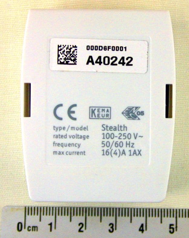
Click to zoom
Application Details
- Equipment Class
- DTS - Digital Transmission System
- Date of Grant
- Oct 02, 2012
- Application Purpose
- Original Equipment
- Date of Application
- Oct 01, 2012
- Equipment Note
- Plugwise Network Device
- Frequency Range
- 2405.00000000 - 2480.00000000
- Company
- Plugwise B.V.
- Country
- Netherlands
Documents & Files
Document Text
Text extracted from the exhibit documents filed with the FCC. Open a document above to read the original.
Users Manual
FCC Declarations Compliance statement (part 15.19) This device complies with part 15 of the FCC Rules. Operation is subject to the following two conditions: (1) this device may not cause harmful interference, and (2) this device must accept any interference received, including interference that may cause undesired operation. Warning (part 15.21) Changes or modifications not expressly approved by the party responsible for compliance could void the user’s authority to operate the equipment. This in particular is applicable for the antenna which has been delivered with any of the Pugwise products mentioned in the list below. FCC ID: ZB9-STICK ZB9-CIRCLE-PLUS ZB9-CIRCLE ZB9-STEALTH-PLUS ZB9-STEALTH ZB9-STEALTH-PLUS ZB9-STEALTH ZB9-SWITCH ZB9-SCAN ZB9-SENSE Plugwise user manual attestation. Version 2012.1 Product: Stick Circle+ Circle Stealth+ Stealth Sting+ Sting Switch Scan Sense
Users Manual
Sense 200.106.110211 Climate monitoring and management Manual 23 Sense Manual Thank you for buying this extension to your Plugwise system. With the Sense, you can wirelessly measure the temperature and air humidity in a room. In this way, you easily obtain insight into the climate in one or more rooms. The temperature sensor has a range of 0 to 60 ̊C; the air-humidity sensor has a range of 5 to 95% RH. You can also link switch actions to certain measurement values. This does not require the computer to be left on. This manual describes the installation of a single Sense, but the same steps can be followed if you want to install multiple Senses at the same time. Before you start • We recommend that you follow this manual carefully; it is essential to take the steps in the correct order. • To be able to use the Sense, you will require a Plugwise network consisting of at least a Stick or Stretch and a Circle+. A Plugwise network can never contain more Senses than 5 times the number of Circles. What this manual explains for the Circle also applies to the Stealth and the Sting, or a combination thereof. • Ensure that you use the latest version of Source and that your modules have the latest firmware version. You can check this by clicking the Updates button in Source. The Sense is only supported if all other modules have firmware version 2.36 (as of 13-05-2011) or later. If this is not yet the case, prior to the installation of the Sense, the other modules must first be updated. In Source, check whether the Stick and all of the modules are online. • In Source, check whether the tick at the bottom left of the screen shows that the Stick is online: • In Source, check in the tree at ‘Overviews’ to see whether all devices are online. This is indicated by grey and yellow lights: • Only insert the battery when you start to use the Sense. A Sense uses a great deal more power if it is not connected to a Plugwise network. • To use the Sense, it must be connected to a Plugwise network. The Sense can then be mounted on a wall. These steps are explained in more detail below. • Check whether all components are present. If a component is missing, please contact us as soon as possible. Contents of the package • Per Sense: 1 3,6V AA battery This manual SenseMounting plate Sens e 200 .106 .11021 1 Clima te monit oring and management Manual 45 1. Adding the Sense to your Plugwise network ÌStart Source and select Settings, Add Modules. ÌWhen you are asked to select a network, select the network to which the Sense must be added. ÌFill in the ID of the Sense. This ID is indicated on the stickers that are attached to the back. ÌClick the button with the green arrow: Next, insert the AA battery in the Sense. Note the + and - marks. ÌIf you want to install multiple Senses, add the IDs for all of the Senses to the list. The Plugwise network will then search for the Senses with the new IDs in the list. Wait until Source indicates that the Sense is online. The circle with the question mark will then change into the following icon: If the Sense is not found within several minutes, check whether the Plugwise network is operating correctly (refer to ‘Before you start’). If the Stick and the other modules are available in Source and the Sense is still not shown as being online, follow the instructions to delete the network settings under ‘Delete network settings’, see: ‘Advanced use’. ÌClick ‘Next’ and then ‘Finish’. ÌThe Sense is now connected to your network. 2. Attaching the Sense to the wall Up/Window > < Reset ÌTake the Sense to the location where it must be installed. This must be within 5 to 10 metres of a Circle. ÌCheck whether Source still indicates that the Sense is online. It can take several minutes for the network to process the new location of the Sense. ÌAttach the Sense mounting plate to the wall. The Up/ Window arrow on the inside of the mounting plate indicates the top. Ensure that the Plugwise logo on the front ends up in a horizontal position (see the corresponding figure). The optimal height of the Sense is 1.50 to 1.80 metres above the floor. In addition, the Sense must not be installed in direct sunlight, above a central heater and preferably not near a door or window. This can negatively impact the functioning of the Sense. ÌWhen the mounting plate is attached to the wall, slide the Sense from above onto the plate until you feel the Sense click into place. 3. Use Communication in the network The Sense contacts one of the Circles in your network. This Circle transmits the measurement data to the other Circles. If the Circle that the Sense tries to contact is unavailable, a connection will be made with another Circle. This can take several seconds. The time interval between two transmissions of measurement data can be specified. As standard, the Sense is set to a transmission interval of 15 minutes. The computer does not need to be switched on to be able to use the Sense. Switching and insight The Sense can be set up to send switch commands if certain temperature or air-humidity values are exceeded: an On or Off command can be sent to appliances or lighting specified in advance within the Plugwise network. While doing so, the Sense does not take into account other switching actions in the network, such as those from the Plugwise Switch or Plugwise Source. As standard, switching actions from the Sense are switched off. It is not recommended to use the Sense as a thermostat. An overview of the options for linking switching actions to the Sense in Source as well as other software functions is available in the latest Source manual. The manual is available at www.plugwise.com/manuals. 67 Removing Sense If the Sense will (temporarily) no longer be used, it can be removed from the Plugwise network. ÌStart Source and go to Settings, Devices. ÌThe list of ‘Non-assigned modules’ is displayed to the right of the screen. Right-click the Sense and then click ‘Delete’. ÌThe Sense will now be ignored by the network.…
Text truncated - open the document above for the full version.
Cover Letter(s)
TÜV Rheinland EPS B.V. Eiberkamp 10 9351VT Leek The Netherlands www.tuv.com/nl T +31 594 505005 F +31 594 504804 E [email protected] Subject Request for confidentiality Date June 14, 2012 Our reference -- Your reference -- Page 1 of 1 Our General Terms and Conditions, as filed at the Chamber of Commerce in Groningen, are applicable to all orders given to TÜV Rheinland EPS B.V. TÜV Rheinland EPS B.V. is registered at the Chamber of Commerce in Groningen with no. 27247331. ® TÜV, TUEV and TUV are registered trademarks. Utilisation and application requires prior approval. ACB Attn.: Mrs. M. Bosley Certification Department 6731 Whittier Avenue, Suite C110 McLean, Virginia 22101 USA Dear Mrs. Bosley, Pursuant to section 0.457(d)(2)(i) and Section 0.459 of the FCC rules we herewith request the following exhibits, related to this application for FCC ID: ZB9-STEALTH be withheld from public inspection and to be kept confidential. The contents of these exhibits may not be disclosed to other parties than Plugwise B.V. and TÜV Rheinland EPS B.V.: 1. Circuit diagram 2. Block diagram 3. Operational description The reason for this request for confidentiality is that the information contained in the exhibits as listed above has been classified as company confidential. Disclosure of any portion of this information to other parties would cause substantial competitive harm. Best regards, TÜV Rheinland EPS B.V. R .van der Meer Test Engineer
Cover Letter(s)
TÜV Rheinland EPS B.V. Eiberkamp 10 9351VT Leek The Netherlands www.tuv.com/nl T +31 594 505005 F +31 594 504804 E [email protected] Subject Antenna info Date August 27, 2012 Our reference -- Your reference -- Page 1 of 1 Our General Terms and Conditions, as filed at the Chamber of Commerce in Groningen, are applicable to all orders given to TÜV Rheinland EPS B.V. TÜV Rheinland EPS B.V. is registered at the Chamber of Commerce in Groningen with no. 27247331. ® TÜV, TUEV and TUV are registered trademarks. Utilisation and application requires prior approval. ACB Attn.: Mrs. M. Bosley Certification Department 6731 Whittier Avenue, Suite C110 McLean, Virginia 22101 USA Dear Mrs. Bosley, On behalf of our customer Plugwise B.V. , we hereby declare that the antenna of the following device: FCC ID: ZB9-STEALTH Brand: Plugwise Model: Stealth Description: Digital Transmission System (DTS). The antenna is fixed to the PCB and part of the device. The antenna used is a chip antenna, Manufacturer:MURATA Model: ANCV12G44SAA127. Max Gain = -5.9 dBi. See for details the photographs of the interior of the device (exibit 09). Best regards, TÜV Rheinland EPS B.V. R. van der Meer Test Engineer
External Photos
Testing and certification of electronic and electric appliances, systems, installations and telecommunication systems TÜV Rheinland EPS B.V. P.O. Box 37 9350 AA Leek (NL) Eiberkamp 10 9351 VT Leek (NL) Telephone: +31 594 505005 Telefax: +31 594 504804 Internet: www.tuv-eps.com E-mail: [email protected] Project number: 12030804_ZB9-STEALTH.p02 Page 1 of 8 PHOTOGRAPHS OF THE EXTERIOR OF A DIGITAL TRANSMISSION SYSTEM BRAND PLUGWISE, MODEL STEALTH AND MODEL STING FCC listed Industry Canada VCCI Registered R&TTE, LVD, EMC Notified Body : : : : 90828 2932G-2 R-1518, C-1598 1856 Description of EUT: Manufacturer: Brand mark: Model: FCC ID: IC: Digital Transmission System (DTS) Applied Micro Electronics “AME” BV Plugwise Stealth and Sting ZB9-STEALTH N/A Project number: 12030804_ZB9-S.p02 Page 2 of 8 Description of test item Test item : Digital Transmission System (DTS) Manufacturer : Applied Micro Electronics “AME” BV Brand : Plugwise Model(s) : Stealth and Sting Serial number(s) : -- Revision : n.a. Receipt date : April 20, 2012 Applicant information Applicant's representative : Mr. R. Van Rooijen Company : Plugwise B.V. Address : Wattstraat 56 Postal code : 2171TR City : Sassenheim Country : The Netherlands Telephone number : +31 252433070 Telefax number : +31 252433079 Description of EUT: Manufacturer: Brand mark: Model: FCC ID: IC: Digital Transmission System (DTS) Applied Micro Electronics “AME” BV Plugwise Stealth and Sting ZB9-STEALTH N/A Project number: 12030804_ZB9-S.p02 Page 3 of 8 Table of contents 1 PHOTOGRAPHS OF THE EQUIPMENT. ....................................................................................................................... 4 1.1 EXTERNAL VIEW. ............................................................................................................................................................ 4 1.1.1 Front view.............................................................................................................................................................. 4 1.1.2 Rear view .............................................................................................................................................................. 5 1.1.3 Side view ............................................................................................................................................................... 6 1.1.4 Top view ................................................................................................................................................................ 7 1.1.5 Bottom view .......................................................................................................................................................... 7 1.2 EXTERNAL VIEW MODEL STING...................................................................................................................................... 8 Description of EUT: Manufacturer: Brand mark: Model: FCC ID: IC: Digital Transmission System (DTS) Applied Micro Electronics “AME” BV Plugwise Stealth and Sting ZB9-STEALTH N/A Project number: 12030804_ZB9-S.p02 Page 4 of 8 1 Photographs of the equipment. 1.1 External view. 1.1.1 Front view Description of EUT: Manufacturer: Brand mark: Model: FCC ID: IC: Digital Transmission System (DTS) Applied Micro Electronics “AME” BV Plugwise Stealth and Sting ZB9-STEALTH N/A Project number: 12030804_ZB9-S.p02 Page 5 of 8 1.1.2 Rear view Description of EUT: Manufacturer: Brand mark: Model: FCC ID: IC: Digital Transmission System (DTS) Applied Micro Electronics “AME” BV Plugwise Stealth and Sting ZB9-STEALTH N/A Project number: 12030804_ZB9-S.p02 Page 6 of 8 1.1.3 Side view Description of EUT: Manufacturer: Brand mark: Model: FCC ID: IC: Digital Transmission System (DTS) Applied Micro Electronics “AME” BV Plugwise Stealth and Sting ZB9-STEALTH N/A Project number: 12030804_ZB9-S.p02 Page 7 of 8 1.1.4 Top view 1.1.5 Bottom view Description of EUT: Manufacturer: Brand mark: Model: FCC ID: IC: Digital Transmission System (DTS) Applied Micro Electronics “AME” BV Plugwise Stealth and Sting ZB9-STEALTH N/A Project number: 12030804_ZB9-S.p02 Page 8 of 8 1.2 External view Model Sting Model Sting is basicly the same as Model Stealth only with power leads added.
ID Label/Location Info
Plugwise Stealth ver. 20120614 FCC marking sticker: Position on backside: FCC ID: ZB9-STEALTH type / model rated voltage frequency max current Stealth 100-230 V~ 50/60 Hz 16(4)A 1AX 000D6F0000 XXX XXX 000D6F0000 XXX XXX FCC ID: ZB9-STEALTH
Internal Photos
Testing and certification of electronic and electric appliances, systems, installations and telecommunication systems TÜV Rheinland EPS B.V. P.O. Box 37 9350 AA Leek (NL) Eiberkamp 10 9351 VT Leek (NL) Telephone: +31 594 505005 Telefax: +31 594 504804 Internet: www.tuv-eps.com E-mail: [email protected] Project number: 12030804_ZB9-STEALTH.p01 Page 1 of 9 PHOTOGRAPHS OF THE INTERIOR OF A DIGITAL TRANSMISSION SYSTEM BRAND PLUGWISE, MODEL STEALTH AND MODEL STING. FCC listed Industry Canada VCCI Registered R&TTE, LVD, EMC Notified Body : : : : 90828 2932G-2 R-1518, C-1598 1856 Description of EUT: Manufacturer: Brand mark: Model: FCC ID: IC: Digital Transmission System (DTS) Applied Micro Electronics “AME” BV Plugwise Stealth and Sting ZB9-STEALTH N/A Project number: 12030804_ZB9-STEALTH.p01 Page 2 of 9 Description of test item Test item : Digital Transmission System (DTS) Manufacturer : Applied Micro Electronics “AME” BV Brand : Plugwise Model(s) : Stealth and Sting Serial number(s) : -- Revision : n.a. Receipt date : April 20, 2012 Applicant information Applicant's representative : Mr. R.van Rooijen Company : Plugwise B.V. Address : Wattstraat 56 Postal code : 2171TR City : Sassenheim Country : The Netherlands Telephone number : +31 252433070 Telefax number : +31 252433079 Description of EUT: Manufacturer: Brand mark: Model: FCC ID: IC: Digital Transmission System (DTS) Applied Micro Electronics “AME” BV Plugwise Stealth and Sting ZB9-STEALTH N/A Project number: 12030804_ZB9-STEALTH.p01 Page 3 of 9 Table of contents 1.1 OVERVIEW, OPENED EUT. ............................................................................................................................................. 4 1.2 OPENED EUT OVERVIEW, PCB REMOVED FROM HOUSING .......................................................................................... 5 1.3 MAIN PCB ...................................................................................................................................................................... 6 1.3.1 Main PCB front view ............................................................................................................................................ 6 1.3.2 Main PCB rear view ............................................................................................................................................. 7 1.3.3 ZigBee PCB view, component side ................................................................................................................... 8 1.3.4 ZigBee PCB view, back side .............................................................................................................................. 8 1.4 INTERNAL VIEW MODEL STING ....................................................................................................................................... 9 Description of EUT: Manufacturer: Brand mark: Model: FCC ID: IC: Digital Transmission System (DTS) Applied Micro Electronics “AME” BV Plugwise Stealth and Sting ZB9-STEALTH N/A Project number: 12030804_ZB9-STEALTH.p01 Page 4 of 9 1.1 Overview, opened EUT. Description of EUT: Manufacturer: Brand mark: Model: FCC ID: IC: Digital Transmission System (DTS) Applied Micro Electronics “AME” BV Plugwise Stealth and Sting ZB9-STEALTH N/A Project number: 12030804_ZB9-STEALTH.p01 Page 5 of 9 1.2 Opened EUT overview, PCB removed from housing Description of EUT: Manufacturer: Brand mark: Model: FCC ID: IC: Digital Transmission System (DTS) Applied Micro Electronics “AME” BV Plugwise Stealth and Sting ZB9-STEALTH N/A Project number: 12030804_ZB9-STEALTH.p01 Page 6 of 9 1.3 Main PCB 1.3.1 Main PCB front view Description of EUT: Manufacturer: Brand mark: Model: FCC ID: IC: Digital Transmission System (DTS) Applied Micro Electronics “AME” BV Plugwise Stealth and Sting ZB9-STEALTH N/A Project number: 12030804_ZB9-STEALTH.p01 Page 7 of 9 1.3.2 Main PCB rear view Description of EUT: Manufacturer: Brand mark: Model: FCC ID: IC: Digital Transmission System (DTS) Applied Micro Electronics “AME” BV Plugwise Stealth and Sting ZB9-STEALTH N/A Project number: 12030804_ZB9-STEALTH.p01 Page 8 of 9 1.3.3 ZigBee PCB view, component side 1.3.4 ZigBee PCB view, back side Antenna Description of EUT: Manufacturer: Brand mark: Model: FCC ID: IC: Digital Transmission System (DTS) Applied Micro Electronics “AME” BV Plugwise Stealth and Sting ZB9-STEALTH N/A Project number: 12030804_ZB9-STEALTH.p01 Page 9 of 9 1.4 Internal view Model Sting The Model Sting is basicly the same as model Stealth with only added power leads.
Test Report
FCC ID: ZB9-STEALTH IC: N/A Test Report No.: 12030804.fcc04 Page 1 of 37 Client: Plugwise B.V. Wattstraat 56, 2171TR Sassenheim Test Item: Digital Transmission System (DTS) Built-in module for wireless energy measuring and switching, ZigBee device Identification: Serial No.: ---- Project No.: 12030804 Date of Receipt: 2012-04-20 Testing Location: TÜV Rheinland EPS B.V. Eiberkamp 10 9351VT Leek Test Specification: FCC 47 CFR Part 15, Subpart C, Section 15.247 (October 1, 2010) ANSI C63.4-2009 KDB Publication No. 558074 D01: Measurement of Digital Transmission Systems Operating under Section 15.247 (January 18, 2012) Test Result: The test item passed the test specification(s). Testing Laboratory: TÜV Rheinland EPS B.V. Eiberkamp 10 9351VT Leek The Netherlands Tested by: 2012-09-10 R. van der Meer / Inspector Date Name/Position Signature Reviewed by: 2012-09-10 O. Hoekstra / Reviewer Date Name/Position Signature Other Aspects: N/A Abbreviations: P(ass) = passed F(ail) = failed N/A = not applicable N/T = not tested This report shall not be reproduced, except in full, without the written permission of TÜV Rheinland EPS B.V. The test results relate only to the item(s) tested. . FCC ID: ZB9-STEALTH IC: N/A Test Report No.: 12030804.fcc04 Page 2 of 37 TEST SUMMARY 5.1.1 VOLTAGE REQUIREMENTS RESULT: PASS 5.1.2 ANTENNA REQUIREMENTS RESULT: PASS 5.1.3 RESTRICTED BANDS OF OPERATION RESULT: PASS 5.2.1 CONDUCTED OUTPUT POWER RESULT: PASS 5.2.2 6DB BANDWIDTH RESULT: PASS 5.2.3 CONDUCTED SPURIOUS EMISSION RESULT: PASS 5.2.4 PEAK POWER SPECTRAL DENSITY RESULT: PASS 5.2.5 BAND EDGE CONDUCTED EMISSIONS RESULT: Pass 5.2.6 RADIATED SPURIOUS EMISSIONS OF TRANSMITTER RESULT: PASS 5.3.1 AC POWER LINE CONDUCTED EMISSION OF TRANSMITTER RESULT: PASS FCC ID: ZB9-STEALTH IC: N/A Test Report No.: 12030804.fcc04 Page 3 of 37 Contents 1. GENERAL REMARKS ............................................................................................... 4 1.1 COMPLEMENTARY MATERIALS ................................................................................. 4 2. TEST SITES ............................................................................................................ 4 2.1 TEST FACILITIES ..................................................................................................... 4 2.2 LIST OF TEST AND MEASUREMENT INSTRUMENTS ...................................................... 5 2.3 MEASUREMENT UNCERTAINTY ................................................................................. 6 3. GENERAL PRODUCT INFORMATION ........................................................................... 7 3.1 PRODUCT FUNCTION AND INTENDED USE .................................................................. 7 3.2 SYSTEM DETAILS .................................................................................................... 7 3.3 CLOCK FREQUENCIES ............................................................................................. 8 3.4 COUNTERMEASURES TO ACHIEVE EMC COMPLIANCE ................................................ 8 4. TEST SET-UP AND OPERATION MODES ..................................................................... 9 4.1 TEST METHODOLOGY .............................................................................................. 9 4.2 OPERATION MODES ................................................................................................ 9 4.3 PHYSICAL CONFIGURATION FOR TESTING ................................................................. 9 4.4 TEST SOFTWARE .................................................................................................. 10 4.5 SPECIAL ACCESSORIES AND AUXILIARY EQUIPMENT ............................................... 11 5. TEST RESULTS R ADI O ....................................................................................... 13 5.1 TECHNICAL REQUIREMENTS ................................................................................... 13 5.1.1 Voltage Requirements ............................................................................................................... 13 5.1.2 Antenna Requirements .............................................................................................................. 13 5.1.3 Restricted Bands of Operation ................................................................................................... 14 5.2 CONDUCTED MEASUREMENTS AT ANTENNA PORT ................................................... 15 5.2.1 Conducted Output Power ........................................................................................................... 15 5.2.1.2 6dB Bandwidth ........................................................................................................................... 17 5.2.3 Conducted Spurious Emission ................................................................................................... 20 5.2.4 Peak Power Spectral Density .................................................................................................... 24 5.2.5 Band Edge Conducted Emissions ............................................................................................. 27 5.2.6 Radiated Spurious Emissions of Transmitter ............................................................................. 30 5.3 AC POWER LINE CONDUCTED MEASUREMENTS ...................................................... 35 5.3.1 AC Power Line Conducted Emission of Transmitter .................................................................. 35 6. LIST OF TABLES .................................................................................................... 37 7. LIST OF FIGURES .................................................................................................. 37 FCC ID: ZB9-STEALTH IC: N/A Test Report No.: 12030804.fcc04 Page 4 of 37 1. General Remarks 1.1 Complementary Materials There is no attachment to this test report. 2. Test Sites 2.1 Test Facilities The Federa…
Text truncated - open the document above for the full version.
Test Setup Photos
Testing and certification of electronic and electric appliances, systems, installations and telecommunication systems TÜV Rheinland EPS B.V. Eiberkamp 10 9351VT Leek The Netherlands Telephone: +31 594 505005 Telefax: +31 594 504804 Internet: www.tuv.com/nl E-mail: [email protected] Project number: 12030804.p03 Page 1 of 7 PHOTOGRAPHS OF THE TESTSETUP OF A DIGITAL TRANSMISSION SYSTEM OPERATING IN THE 2G4 ISM-BAND BRAND PLUGWISE, MODEL STEALTH 12030804.p03 June 26, 2012 FCC listed Industry Canada VCCI Registered R&TTE, LVD, EMC Notified Body : : : : 90828 2932G-2 R-1518, C-1598 1856 Description of EUT: Manufacturer: Brand mark: Model: FCC ID: IC: Digital Transmission Sytem (DTS) Applied Micro Electronics “AME” BV Plugwise Stealth ZB9-STHEALTH N/A Project number: 12030804.p03 Page 2 of 7 Description of test item Test item : Digital Transmission System (DTS) Manufacturer : Applied Micro Electronics “AME” BV Brand : Plugwise Model : Stealth Serial number : -- FCC ID : ZB9-STEALTH IC : N.A. Applicant information Applicant's representative : Mr. R.van Rooijen Company : Plugwise B.V. Address : Wattstraat 56 Postal code : 2171TR City : Sassenheim Country : The Netherlands Telephone number : +31 252433070 Telefax number : +31 252433079 Report written by : R. van der Meer Report date : June 26, 2012 Description of EUT: Manufacturer: Brand mark: Model: FCC ID: IC: Digital Transmission Sytem (DTS) Applied Micro Electronics “AME” BV Plugwise Stealth ZB9-STHEALTH N/A Project number: 12030804.p03 Page 3 of 7 Table of contents 1 PHOTOGRAPHS OF THE TESTSETUP. ....................................................................................................................... 4 1.1 RADIATED EMISSIONS..................................................................................................................................................... 4 1.1.1 Radiated emissions setup .................................................................................................................................. 4 1.1.2 Radiated emissions setup detail ........................................................................................................................ 5 1.2 CONDUCTED TESTS ........................................................................................................................................................ 6 1.3 CONDUCTED EMISSIONS ................................................................................................................................................ 7 1.3.1 Conducted emissions testsetup overview ........................................................................................................ 7 Description of EUT: Manufacturer: Brand mark: Model: FCC ID: IC: Digital Transmission Sytem (DTS) Applied Micro Electronics “AME” BV Plugwise Stealth ZB9-STHEALTH N/A Project number: 12030804.p03 Page 4 of 7 1 Photographs of the testsetup. 1.1 Radiated emissions. 1.1.1 Radiated emissions setup Description of EUT: Manufacturer: Brand mark: Model: FCC ID: IC: Digital Transmission Sytem (DTS) Applied Micro Electronics “AME” BV Plugwise Stealth ZB9-STHEALTH N/A Project number: 12030804.p03 Page 5 of 7 1.1.2 Radiated emissions setup detail Description of EUT: Manufacturer: Brand mark: Model: FCC ID: IC: Digital Transmission Sytem (DTS) Applied Micro Electronics “AME” BV Plugwise Stealth ZB9-STHEALTH N/A Project number: 12030804.p03 Page 6 of 7 1.2 Conducted tests Description of EUT: Manufacturer: Brand mark: Model: FCC ID: IC: Digital Transmission Sytem (DTS) Applied Micro Electronics “AME” BV Plugwise Stealth ZB9-STHEALTH N/A Project number: 12030804.p03 Page 7 of 7 1.3 Conducted emissions 1.3.1 Conducted emissions testsetup overview Photo . Basic test set-up conducted emission Photo . Detail test set-up conducted emission
Contact Information
Applicant
Norbert Vroege(CEO)
Technical Contact
Non-Technical Contact
Plugwise B.V.Remy van Rooijen
[email protected]+31252433074
Test Firm
TUV Rheinland Nederland B.V.Wiebe Boekema
Technical Specifications
| # | Rule Parts | Frequency Range | Power Output |
|---|---|---|---|
| 1 | 15C | 2.40 GHz - 2.48 GHz | 1.17 mW |
Other Applications from Plugwise B.V.
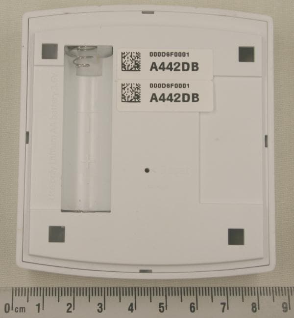
ZB9-SENSE
Oct 02, 2012Plugwise Network Device
Equipment Class
DTS - Digital Transmission System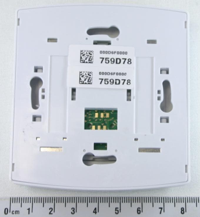
ZB9-SWITCH
Oct 02, 2012Plugwise Network Device
Equipment Class
DTS - Digital Transmission System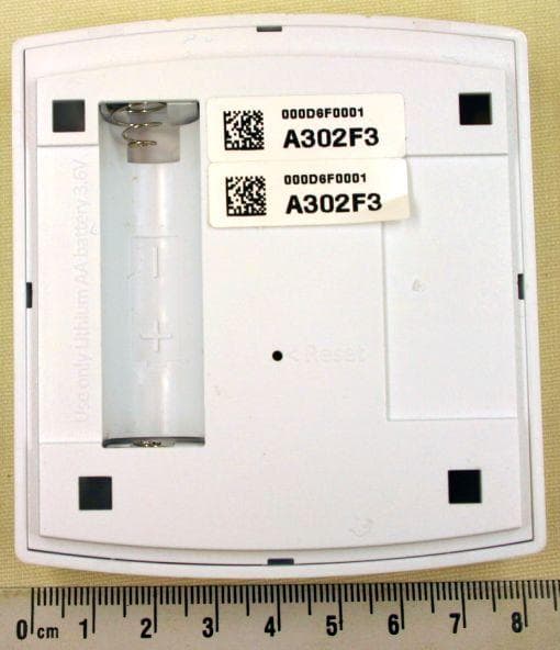
ZB9-SCAN
Oct 02, 2012Plugwise Network Device
Equipment Class
DTS - Digital Transmission System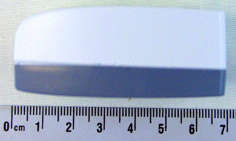
ZB9-STEALTH-PLUS
Oct 02, 2012Plugwise Network Device
Equipment Class
DTS - Digital Transmission System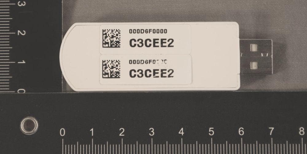
ZB9-STICK
Aug 08, 2011Plugwise Stick
Equipment Class
JBP - Part 15 Class B Computing Device Peripheral