ZBG-ATRUHF-1UHF ATR
Koos Technical Services, Inc
Click to zoom
Application Details
- Equipment Class
- TNB - Licensed Non-Broadcast Station Transmitter
- Date of Grant
- Apr 11, 2013
- Application Purpose
- Original Equipment
- Date of Application
- Apr 11, 2013
- Equipment Note
- UHF ATR
- Frequency Range
- 450.00000000 - 470.00000000
- Company
- Koos Technical Services, Inc
- Country
- United States
Documents & Files
Document Text
Text extracted from the exhibit documents filed with the FCC. Open a document above to read the original.
Users Manual
Agility Telemetry Radio (ATR) User Manual Oct 2012 Revision D.2 Quick Start Procedure Note: Prior to starting the installation process, go to the KTS Wireless website (ktswireless.com) and download a copy of the ATR Element Management System (EMS) software. Store this software on your PCs Desktop. Follow the steps below to install and configure Agility Telemetry Radio (ATR): 1. Select the location for the ATR. Must be an area free of water intrusion with a temperature range of -30 to +60 deg C (-22 to 140 deg F). It is always best to use the mounting option shown in Figure 1 below to provide good ‘heat sinking’ of the ATR case to a large metal surface or DIN rail. This will reduce the operating temperature of the ATR and surrounding equipment within the same enclosure. Figure 1: ATR Optional Mounting Bracket See the KTS website for ordering information. Correct mounting is critical to maximizing ATR performance and reliability. 2. Locate the coaxial cable to the antenna. This should be a good quality, low-loss cable that is as short as possible. This cable should include an in-line surge arrestor to prevent lightning strike damage to the radio. The cable should have a BNC (F) connector or an adapter will be needed. See the KTS Wireless website for ordering information, if one is needed. 3. Locate the power source. The ATR requires a 9-24 VDC input and draws about 2.5 A (at 12 VDC) when transmitting. Power is supplied via the Green Terminal Block at the end of the unit (See Figure 2). The mating terminal block connector is supplied with the ATR and can be used to connect to an existing power supply. Alternately, a separate power supply (12 or 24 VDC) can be purchased directly from a OEM supplier provided it meets the FCC or other regulatory requirements when powering the ATR. Power/Fan (TB) Ethernet (RJ45) Antenna (SMA) Serial Data (DB9) Figure 2: ATR Connections The proper wiring for the Terminal Block (TB) is shown in Figure 3 below: +12 to 24 VDC In (Radio) Ground +12 or 24 VDC In (External Fan) 123 Figure 3: ATR Power Connections Note that the radio is powered using pins 1 and 3 and accepts any voltage from 12 to 24 VDC. Pins 2 and 3 can be used to connect to an external fan near the radio if additional cooling is required. A thermostat inside the ATR will turn the fan on and off based on its internal temperature. The maximum current supported (internal fuse) for the fan is 0.75 A at 12 VDC. 4. Once the power is supplied to the ATR, observe that the green power LED is illuminated. It takes about 7-10 seconds for the ATR to boot-up. After this, only the green power LED should be on. Figure 4 summarizes the LEDs and their meaning. Power on (GRN) or Summary Fault (RED) Wireless Link Activity (Amber = TX; Grn= RX) Reset Button (Recessed) (Depress for 12 secs for Factory Defaults) Ethernet Activity (Flashes Yellow) LAN Speed (GRN = 10 Mb/s Off = 100 Mb/s) Figure 4: ATR LEDs and definitions 5. Connect a laptop to the ATR as shown in the Figure 5. Double-click on the icon below to start the EMS software. EMS_2.3.23.6.jar Agility Telemetry Radio (ATR) Laptop Element Management System (EMS) Software Ethernet cable Figure 5: EMS to ATR Connection 6. The Main screen will appear (See Figure 6). Enter a valid password and click on Login. The IP Tab will open if a valid password is entered. Contact KTS Wireless to obtain your password. Section 4.0 of this manual contains the details of using the ATR Element Management System (EMS). Jump to Section 4.0 for details on setting up the EMS and resetting the ATR IP addresses (i.e., changing from the default value). 7. The default IP address of the ATR is 192.168.1.4. This address is automatically loaded in the Connect to field at the top. Click on the GET button at the bottom if this default address is still loaded in the ATR and not been changed. Note: Pressing and holding the recessed Reset button (See Figure 4) for at least 12 seconds will force the radio back to its default settings. The default radio IP address is 192.168.1.4. If the ATR’s IP address is unknown, clicking on the ‘magnifying glass’ icon to the right of the ‘connect to’ will initiate a search. If it is discovered in the search, a pop-up window will appear with the unit’s serial number and IP address. 8. Open the Configuration Tab. Select the Link Configuration (channel bandwidth) from the pull-down menu. Enter the desired Frequency in Hz (with or without commas separators). Make sure the desired frequency is supported by the RF Card installed in the ATR. The following ranges are supported: RF Card Band Frequency Range (MHz) VHF 145.0 to 225.0 (Band 15 or 26) UHF 450.0 to 470.0 (Band 28) The ATR configuration printed label (on the bottom side) indicates the RF Band supported (VHF or UHF). Verification of the Radio band can be found on the SW/HW tab (RF Band is displayed in the upper right of the tab). 9. Set the Transmit Power level. Valid entries are 10 to 37 (dBm) depending on the model . 10. Enter the Radio Type (Remote or Hub). All networks require a single hub. This Hub radio controls the Media Access Control (MAC) software and implements a round-robin polling of all remote sites that have ‘joined’ the network. All remote sites automatically join the Hub/network if they are configured with the same frequency and link configuration as the hub and have sufficient signal strength to communicate with it. 11. Enter the Site Name (optional). This is a convenient name for the location or site and can be used by operation staff for identification. Its value does not affect radio operation. Up to 15 characters can be entered. This name is used by the optional Network Performance Software (NPM) to display the status of sites and send alerts. It is recommended that a unique name be given to each site. 12. Click on SET to make the desired Configuration changes within the ATR. The ATR will automatically reset and begin using the new configuration information. Allow about 7- 10 seconds for this …
Text truncated - open the document above for the full version.
External Photos
AT R Enclosure AT R Enclosure Ends Front Back
ID Label/Location Info
ATR FCC Labels 26” VHF This device complies with part 15 of the FCC Rules. Operation is subject to the condition that this device does not cause harmful interference. Agility Tl t Rdi Input Power: 12 to 24 VDC, 2.5A Operating Temp Range: ‐ 30 to + 60 C 2 . 6” 1.0” T e l eme t ry R a di o Made in U.S.A Operating Temp Range: 30 to 60 C FCC ID: ZBG ‐ ATRVHF ‐ 1 ATR-US-VHF-100 UHF This device complies with part 15 of the FCC Rules. Operation is subject to the condition that this device does not cause harmful interference. Agility Telemetry Radio Input Power: 12 to 24 VDC, 2.5A Operating Temp Range: ‐ 30 to +60 C UHF Telemetry Radio Made in U.S.A FCC ID: ZBG ‐ ATRUHF ‐ 1 ATR-US-UHF-100 Label Location Label Location This device complies with part 15 of the FCC Rules. Operation is subject to the condition that this device does not cause harmful interference. Agility In p ut Power: 9 to 24 VDC , 2.5A Agility Telemetry Radio Made in U.S.A p , Operating Temp Range: ‐ 30 to +60 C FCC ID: ZBG ‐ ATRVHF ‐ 1
ID Label/Location Info
ATR VHF FCC Labels VHF-1 (150 – 174 MHz) This device complies with part 15 of the FCC Rules. Operation is subject to the condition that this device does not cause harmful interference. Agility Telemetry Radio Made in U.S.A Input Power: 12 to 24 VDC, 2.5A Operating Temp Range: -30 to +60 C FCC ID: ZBG-ATRVHF-1 ATR-US-VHF-100 This device complies with part 15 of the FCC Rules. Operation is subject to the condition that this device does not cause harmful interference. Agility Telemetry Radio Made in U.S.A Input Power: 12 to 24 VDC, 2.5A Operating Temp Range: -30 to +60 C FCC ID: ZBG-ATRVHF-2 ATR-US-VHF-120 2.6” 1.0” VHF-2 (217 - 220 MHz) ATR UHF FCC Label UHF (450 – 470 MHz) This device complies with part 15 of the FCC Rules. Operation is subject to the condition that this device does not cause harmful interference. Agility Telemetry Radio Made in U.S.A Input Power: 12 to 24 VDC, 2.5A Operating Temp Range: -30 to +60 C FCC ID: ZBG-ATRUHF-1 ATR-US-UHF-100 Label Location
Internal Photos
UHF RF Board -Top UHF RF Board -Bottom UHF RF Board –Top (No Shields)
Parts List/Tune Up Info
1025 Greenwood Blvd., Suite 391 Lake Mary, FL 32746 Phone: 407.260.0564; Fax: 407.333.3620 www.koostech.com Tuning Procedure UHF ATR (ZBG-ATRUHF-1) The KTS UHF Agility Telemetry Radio (ATR) includes an internal frequency synthesizer with a 20 MHz Frequency Reference. This Reference a Temperature-Compensated Crystal Oscillator (TCXO) with Stratum 3 frequency stability. This reference is multiplied up to the desired operating frequency within the Synthesizer. This TCXO is aged and very accurately set at the factory. It will meet the frequency stability and accuracy requirements for the life of the product and does not require any tuning.
RF Exposure Info
Freq (MHz):470 PTransmit Power (mW):3,300.0 GMax Antenna Gain (dB):7.55.623413Linear Gain RDistance (cm):8031.50inches S Power Density (mW/cm 2 ): 0.308 Limits for General Public (mW/cm 2 ): f = 30 - 300 MHz0.2 f = 300 - 1500 MHzf/15000.313 Limits for Occupational Exposure f=30 - 300 MHz1 f = 300 - 1500 MHzf/3001.567 MPE Calculations
Test Report
FCC PART 90 TEST REPORT APPLICANT KOOS TECHNICAL SERVICES 1025 GREENWOOD BLVD SUITE 391 LAKE MARY FLORIDA 32746 FCC ID ZBGATRUHF-1 MODEL NUMBER ATRUHF-1 PRODUCT DESCRIPTION UHF AGILITY TELEMETRY RADIO DATE SAMPLE RECEIVED 5/3/2012 DATE TESTED 6/12/2012 TESTED BY JOE SCOGLIO APPROVED BY MARIO R. DE ARANZETA TIMCO REPORT NO. 1133AUT12TestReport.doc TEST RESULTS PASS FAIL THE ATTACHED REPORT SHALL NOT BE REPRODUCED EXCEPT IN FULL WITHOUT THE WRITTEN APPROVAL OF TIMCO ENGINEERING, INC. TABLE OF CONTENTS 849 NW STATE ROAD 45 NEWBERRY, FL 32669 USA PH: 888.472.2424 OR 352.472.5500 FAX: 352.472.2030 EMAIL: [email protected] HTTP://WWW.TIMCOENGR.COM Certificate # 0955-01 Applicant: KOOS TECHNICAL SERVICES FCC ID: ZBGATRUHF-1 Report: K\KOOS TECHNICAL SERVICES\1133AUT12\1133AUT12TestReport.doc Page 2 of 18 TABLE OF CONTENTS GENERAL REMARKS ........................................................................................................... 3 GENERAL INFORMATION .................................................................................................... 4 TEST PROCEDURES ............................................................................................................ 5 RF POWER OUTPUT ............................................................................................................ 6 SPURIOUS EMISSIONS AT ANTENNA TERMINALS (CONDUCTED) ...................................... 7 FIELD STRENGTH OF SPURIOUS EMISSIONS .................................................................. 10 FREQUENCY STABILITY .................................................................................................... 13 TRANSIENT FREQUENCY BEHAVIOR ................................................................................ 14 EMC EQUIPMENT LIST ...................................................................................................... 18 Applicant: KOOS TECHNICAL SERVICES FCC ID: ZBGATRUHF-1 Report: K\KOOS TECHNICAL SERVICES\1133AUT12\1133AUT12TestReport.doc Page 3 of 18 GENERAL REMARKS The attached report shall not be reproduced except in full without the written permission of Timco Engineering Inc. The test results relate only to the items tested. Summary The device under test does: fulfill the general approval requirements as identified in this test report not fulfill the general approval requirements as identified in this test report Attestations This equipment has been tested in accordance with the standards identified in this test report. To the best of my knowledge and belief, these tests were performed using the measurement procedures described in this report. All instrumentation and accessories used to test products for compliance to the indicated standards are calibrated regularly in accordance with ISO 17025: 2005 requirements. Testing Certificate # 0955-01 I attest that the necessary measurements were made, under my supervision, at: Timco Engineering Inc. 849 NW State Road 45 Newberry, Fl 32669 Authorized Signatory Name: Mario de Aranzeta C.E.T. Compliance Engineer/ Lab. Supervisor Date: June 13, 2012 Applicant: KOOS TECHNICAL SERVICES FCC ID: ZBGATRUHF-1 Report: K\KOOS TECHNICAL SERVICES\1133AUT12\1133AUT12TestReport.doc Page 4 of 18 GENERAL INFORMATION DUT Specification DUT Description UHF AGILITY TELEMETRY RADIO FCC ID ZBGATRUHF-1 Model Number ATRUHF-1 Serial Number N/A Operating Frequency 450-470 MHz Test Frequencies 451.0 MHz, 460.0 MHz, 469.0 MHz DUT Power Source 110–120Vac/50– 60Hz DC Power 12V Battery Operated Exclusively Test Item Prototype Pre-Production Production Type of Equipment Fixed Mobile Portable Test Conditions The temperature was 26ºC Relative humidity of 50%. Modification to the DUT None Test Exercise The DUT was placed in continuous transmit mode. Applicable Standards ANSI/TIA 603-C:2004, FCC CFR 47 Part 90, IC RSS- 119, RSS-GEN Test Facility Timco Engineering Inc. at 849 NW State Road 45 Newberry, FL 32669 USA. Applicant: KOOS TECHNICAL SERVICES FCC ID: ZBGATRUHF-1 Report: K\KOOS TECHNICAL SERVICES\1133AUT12\1133AUT12TestReport.doc Page 5 of 18 TEST PROCEDURES Power Output: The RF power output was measured at the antenna feed point using a peak power meter. Antenna Conducted Emissions: The RBW = 100 kHz, VBW = 300 kHz and the span set to 10.0 MHz and the spectrum was scanned from 30 MHz to the 10 th harmonic of the fundamental. Above 1 GHz the resolution bandwidth was 1 MHz and the VBW = 3 MHz and the span to 50 MHz. Radiation Interference: The test procedure used was ANSI/TIA 603-C: 2004 using an Agilent spectrum receiver with pre-selector. The bandwidth (RBW) of the spectrum receiver was 100 kHz up to 1 GHz and 1 MHz above 1 GHz with an appropriate sweep speed. The VBW above 1 GHz was 3 MHz. The analyzer was calibrated in dB above a micro volt at the output of the antenna. Applicant: KOOS TECHNICAL SERVICES FCC ID: ZBGATRUHF-1 Report: K\KOOS TECHNICAL SERVICES\1133AUT12\1133AUT12TestReport.doc Page 6 of 18 RF POWER OUTPUT Rule Part No.: FCC Part 2.1046(a), IC RSS-119 4.1 and 5.4, RSS-GEN 4.8 Test Requirements: Method of Measurement: RF power is measured by connecting a 50-ohm, resistive wattmeter to the RF output connector. With a transmitter properly adjusted the RF output measures: Test Setup Diagram: Test Data: OUTPUT POWER: HIGH – 3.3 Watts Conducted LOW - 0.009 Watts Conducted Applicant: KOOS TECHNICAL SERVICES FCC ID: ZBGATRUHF-1 Report: K\KOOS TECHNICAL SERVICES\1133AUT12\1133AUT12TestReport.doc Page 7 of 18 SPURIOUS EMISSIONS AT ANTENNA TERMINALS (CONDUCTED) Rule Part No.: FCC Part 2.1051(a), RSS-GEN 7.1.4 Requirements: 12.5 kHz CH spacing– 50+10log(3.3) = 55 6.25 kHz CH spacing - 55+10log(3.3) = 60 Method of Measurement: The carrier was modulated 100%. The spectrum was scanned from 0.4 to at least the 10th harmonic of the fundamental. The measurements were made in accordance with standard ANSI/TIA 603-C: 2004. Test Data: TF HIGH POWER EF dB below carrier TF LOW POWER EF dB below carrier 451.0 451 0 451 451 0 902 76.1 902…
Text truncated - open the document above for the full version.
Test Report
FCC PART 90 TEST REPORT APPLICANT KOOS TECHNICAL SERVICES 1025 GREENWOOD BLVD SUITE 391 LAKE MARY FLORIDA 32746 FCC ID ZBGATRUHF-1 MODEL NUMBER ATRUHF-1 PRODUCT DESCRIPTION UHF AGILITY TELEMETRY RADIO DATE SAMPLE RECEIVED 1/2/2013 DATE TESTED 1/3/2013 TESTED BY Joe Scoglio APPROVED BY Joe Scoglio TIMCO REPORT NO. 1133AUT12TestReport2.doc TEST RESULTS PASS FAIL THE ATTACHED REPORT SHALL NOT BE REPRODUCED EXCEPT IN FULL WITHOUT THE WRITTEN APPROVAL OF TIMCO ENGINEERING, INC. 849 NW STATE ROAD 45 NEWBERRY, FL 32669 USA PH: 888.472.2424 OR 352.472.5500 FAX: 352.472.2030 EMAIL: [email protected] HTTP://WWW.TIMCOENGR.COM Certificate # 0955-01 Applicant: KOOS TECHNICAL SERVICES FCC ID: ZBGATRUHF-1 Report: V:\K\KOOS TECHNICAL SERVICES\329UT13\1133AUT12TestReport2.doc Page 2 of 14 TABLE OF CONTENTS GENERAL REMARKS ................................................................................................... 3 GENERAL INFORMATION ............................................................................................ 4 EQUIPMENT LIST ........................................................................................................ 5 TEST PROCEDURE ...................................................................................................... 6 OCCUPIED BANDWIDTH ............................................................................................. 7 OCCUPIED BANDWIDTH PLOTS ................................................................................. 9 Applicant: KOOS TECHNICAL SERVICES FCC ID: ZBGATRUHF-1 Report: V:\K\KOOS TECHNICAL SERVICES\329UT13\1133AUT12TestReport2.doc Page 3 of 14 GENERAL REMARKS The attached report shall not be reproduced except in full without the written permission of Timco Engineering Inc. Summary The device under test does: fulfill the general approval requirements as identified in this test report not fulfill the general approval requirements as identified in this test report Attestations This equipment has been tested in accordance with the standards identified in this test report. To the best of my knowledge and belief, these tests were performed using the measurement procedures described in this report. All instrumentation and accessories used to test products for compliance to the indicated standards are calibrated regularly in accordance with ISO 17025 requirements. Testing Certificate # 0955-01 I attest that the necessary measurements were made, under my supervision, at: Timco Engineering Inc. 849 NW State Road 45 Newberry, Fl 32669 Authorized Signatory Name: Mario de Aranzeta C.E.T. Compliance Engineer/ Lab. Supervisor Date: January/4/2013 Applicant: KOOS TECHNICAL SERVICES FCC ID: ZBGATRUHF-1 Report: V:\K\KOOS TECHNICAL SERVICES\329UT13\1133AUT12TestReport2.doc Page 4 of 14 GENERAL INFORMATION DUT Specification DUT Description UHF AGILITY TELEMETRY RADIO FCC ID ZBGATRUHF-1 Model Number ATRUHF-1 Serial Number N/A Operating Frequency 450-470 MHz Test Frequencies 451.0 MHz, 460.0 MHz, 469.0 MHz DUT Power Source 110–120Vac/50– 60Hz DC Power 12V Battery Operated Exclusively Test Item Prototype Pre-Production Production Type of Equipment Fixed Mobile Portable Test Conditions The temperature was 26ºC Relative humidity of 50%. Modification to the DUT None Test Exercise The DUT was placed in continuous transmit mode. Applicable Standards ANSI/TIA 603-C:2004, FCC CFR 47 Part 90, IC RSS- 119, RSS-GEN Test Facility Timco Engineering Inc. at 849 NW State Road 45 Newberry, FL 32669 USA. Applicant: KOOS TECHNICAL SERVICES FCC ID: ZBGATRUHF-1 Report: V:\K\KOOS TECHNICAL SERVICES\329UT13\1133AUT12TestReport2.doc Page 5 of 14 EQUIPMENT LIST Device Manufacturer Model Serial Number Cal/Char Date Due Date Analyzer Tan Tower Spectrum Analyzer HP 8566B Opt 462 3138A07786 3144A20661 10/28/11 10/28/13 Analyzer Tan Tower Preamplifier HP 8449B-H02 3008A00372 10/28/11 10/28/13 Antenna: Biconnical Electro- Metrics BIA-25 1171 06/13/12 06/13/14 Antenna: Biconnical Eaton 94455-1 1096 05/04/11 05/04/13 Antenna: Log- Periodic Electro- Metrics LPA-25 1122 05/04/11 05/04/13 Frequency Counter HP 5352B 2632A00165 06/22/11 06/22/13 Frequency Counter HP 5385A 2730A03025 08/17/11 08/17/13 Signal Generator HP 8640B 2308A21464 02/23/12 02/23/14 Hygro- Thermometer Extech 445703 0602 06/15/11 06/15/13 Digital Multimeter Fluke 77 35053830 09/09/11 09/09/13 Analyzer Tan Tower RF Preselector HP 85685A 3221A01400 10/28/11 10/28/13 Antenna: Passive Loop EMC Test Systems EMCO 6512 9706-1211 06/14/12 06/14/14 Analyzer Tan Tower Quasi- Peak Adapter HP 85650A 3303A01690 10/28/11 10/28/13 Temperature Chamber Tenney Engineering TTRC 11717-7 07/03/12 07/03/14 Frequency Counter HP 5385A 3242A07460 06/22/11 06/22/13 3/10-Meter OATS TEI N/A N/A 12/31/11 12/31/13 3-Meter OATS TEI N/A N/A 12/31/11 12/31/13 3-Meter Semi- Anechoic Chamber Panashield N/A N/A 12/31/11 12/31/13 Applicant: KOOS TECHNICAL SERVICES FCC ID: ZBGATRUHF-1 Report: V:\K\KOOS TECHNICAL SERVICES\329UT13\1133AUT12TestReport2.doc Page 6 of 14 TEST PROCEDURE Power Line Conducted Interference: The procedure used was ANSI/TIA 603-C:2004, using a 50uH LISN. Both lines were observed with the UUT transmitting. The bandwidth of the spectrum analyzer was 10 kHz with an appropriate sweep speed. Bandwidth 20 dB: The measurements were made with the spectrum analyzer's resolution bandwidth (RBW) = 1 MHz and the video bandwidth (VBW) = 3 MHz and the span set as shown on plot. Power Output: The RF power output was measured at the antenna feed point using a peak power meter. Antenna Conducted Emissions: The RBW = 100 kHz, VBW = 300 kHz and the span set to 10.0 MHz and the spectrum was scanned from 30 MHz to the 10 th harmonic of the fundamental. Above 1 GHz the resolution bandwidth was 1 MHz and the VBW = 3 MHz and the span to 50 MHz. Radiation Interference: The test procedure used was ANSI/TIA 603-C: 2004, using an Agilent spectrum receiver with pre-selector. The bandwidth (RBW) of the spectrum ANSI/TIA 603-C:2004, receiver was 100 kH…
Text truncated - open the document above for the full version.
Contact Information
Applicant
Ed Gerhardt(VP Operations)
Test Firm
Timco Engineering, Inc.Bruno Clavier
Technical Specifications
| # | Rule Parts | Frequency Range | Power Output | Emission | Tolerance |
|---|---|---|---|---|---|
| 2 | 9 | 450 MHz - 470 MHz | 3.3 W | 11K0F1D | 0.05 ppm |
Other Applications from Koos Technical Services, Inc

ZBG-ATRVHF-1
Apr 07, 2013VHF ATR
Equipment Class
TNB - Licensed Non-Broadcast Station Transmitter
ZBG-ATRVHF-2
Apr 04, 2013VHF ATR
Equipment Class
TNB - Licensed Non-Broadcast Station Transmitter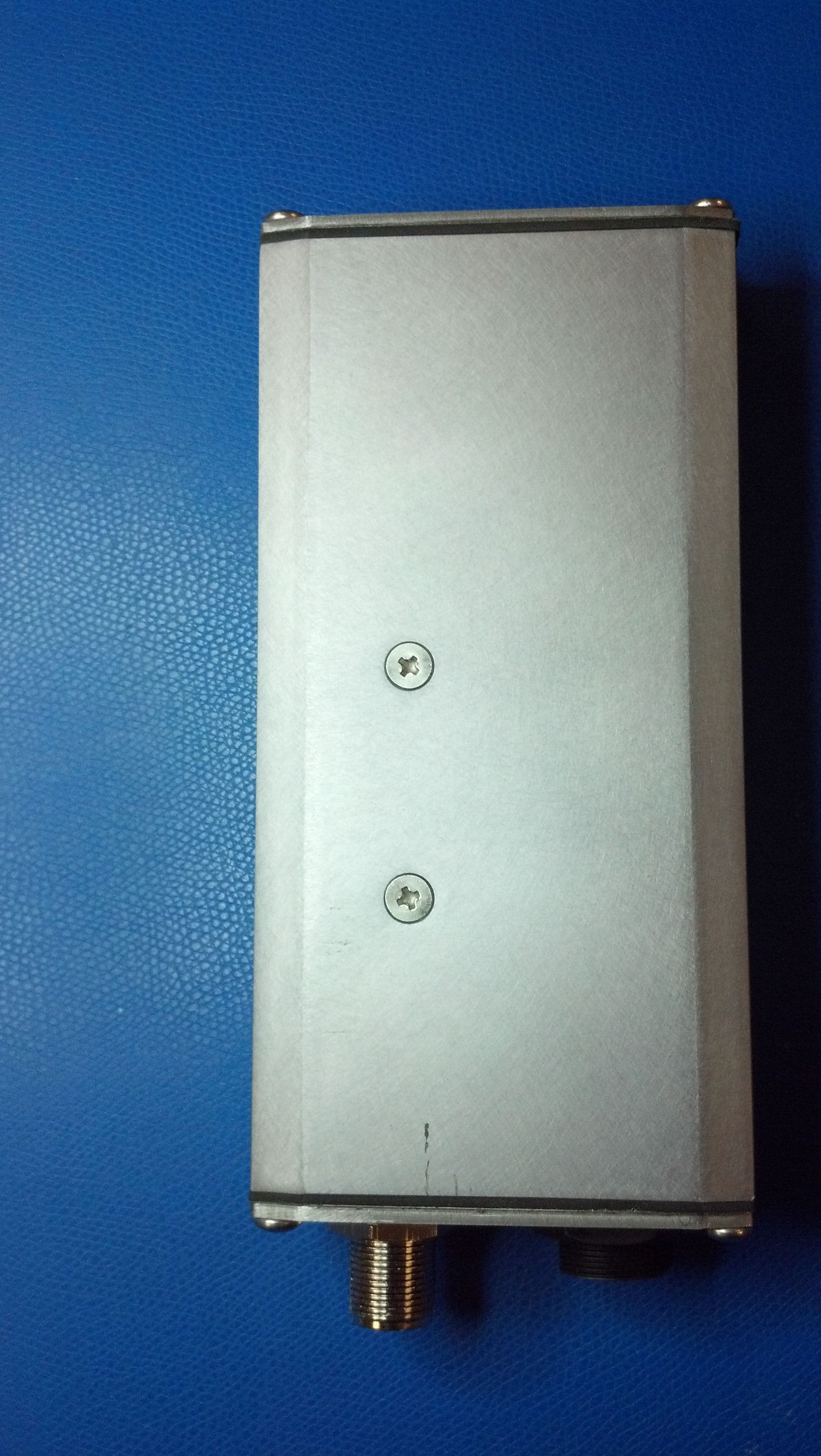
ZBGAWR2UHF
Jun 06, 2012White space radio controlled by database
Equipment Class
WGF - White Space Device with Geo-location- Fixed
ZBGAWR-1
Dec 21, 2011Fixed TVDB
Equipment Class
WGF - White Space Device with Geo-location- Fixed