ZBGAWR2UHFWhite space radio controlled by database
Koos Technical Services, Inc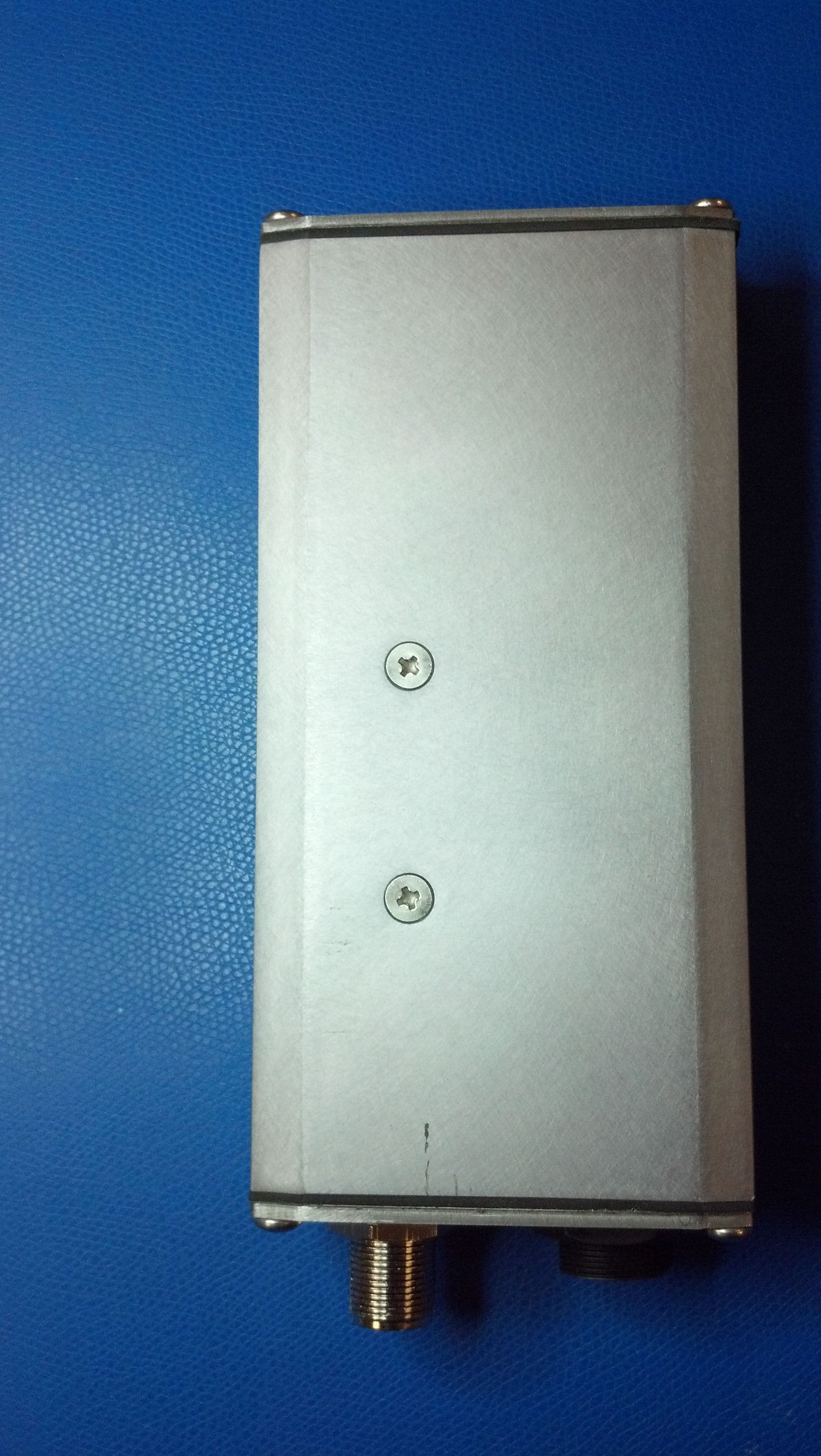
Click to zoom
Application Details
- Equipment Class
- WGF - White Space Device with Geo-location- Fixed
- Date of Grant
- Jun 06, 2012
- Application Purpose
- Original Equipment
- Date of Application
- Dec 04, 2011
- Equipment Note
- White space radio controlled by database
- Frequency Range
- 473.00000000 - 695.00000000
- Company
- Koos Technical Services, Inc
- Country
- United States
Documents & Files
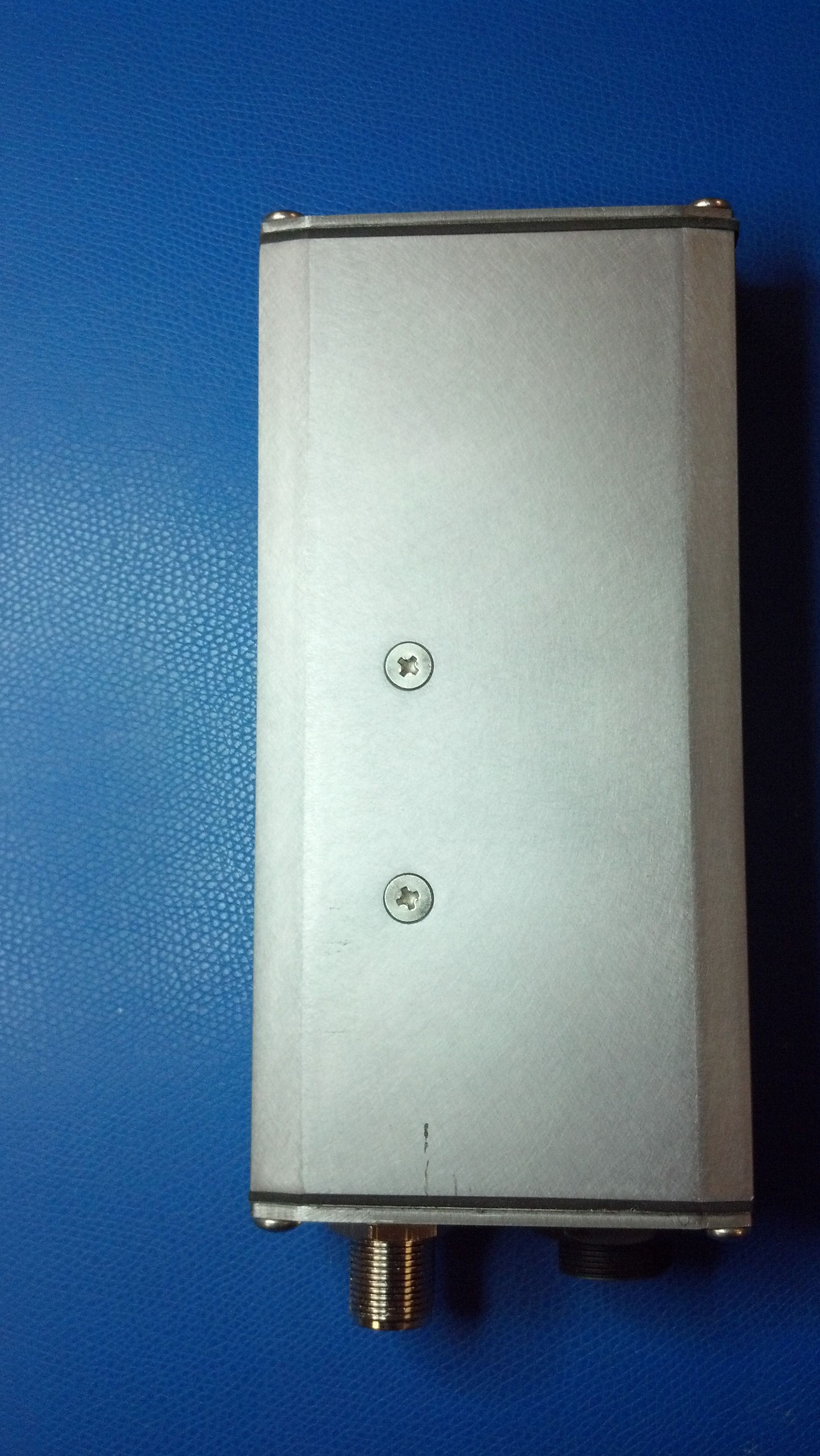
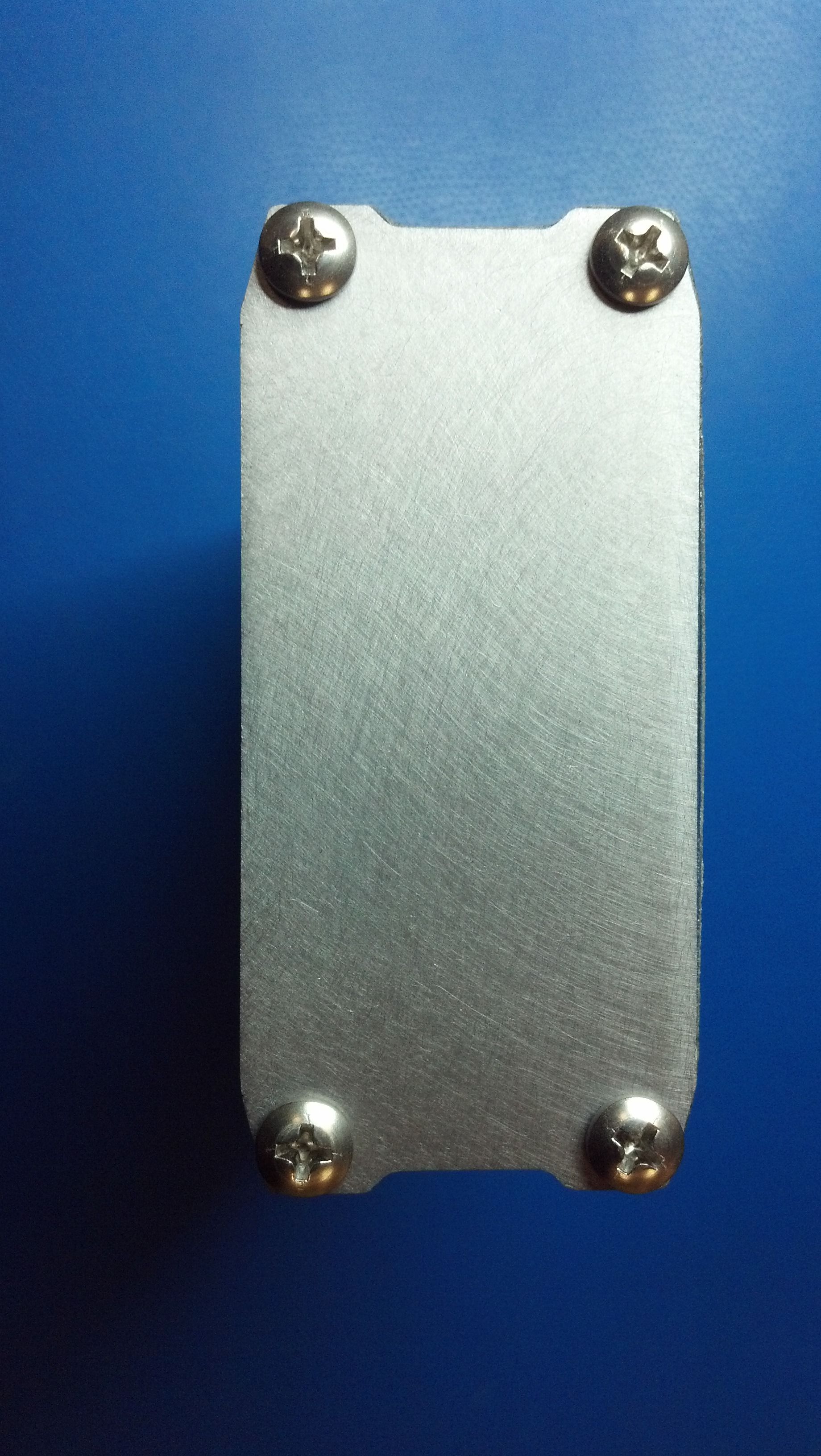
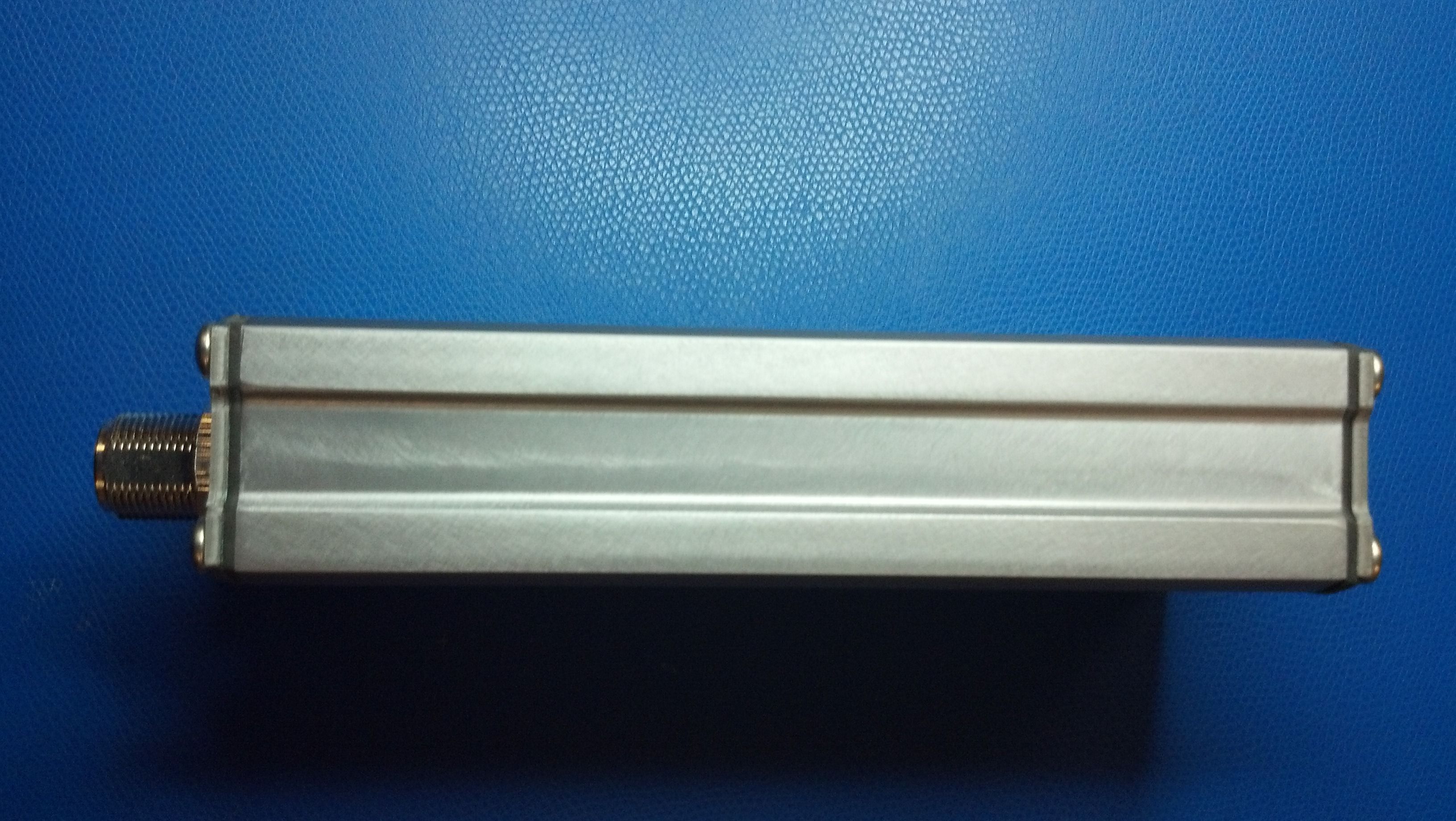
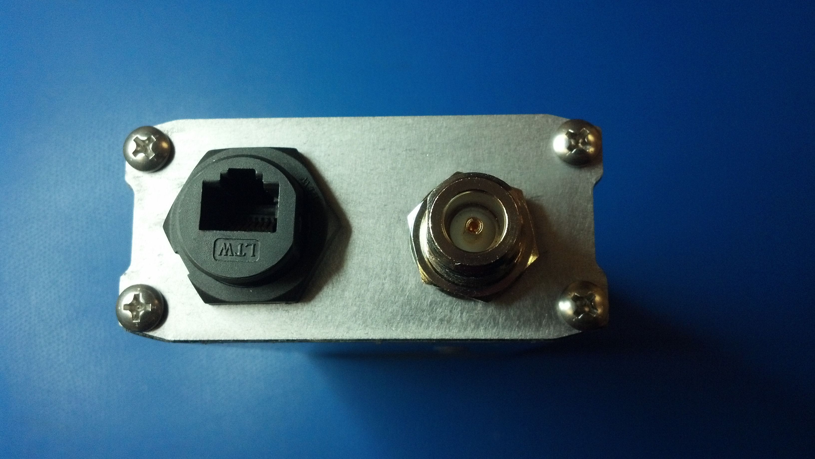
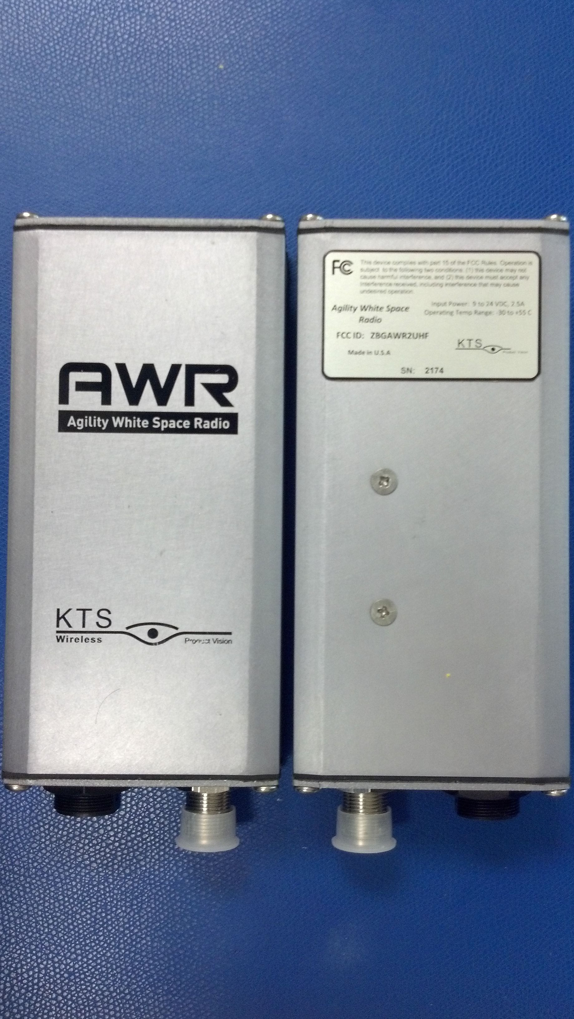
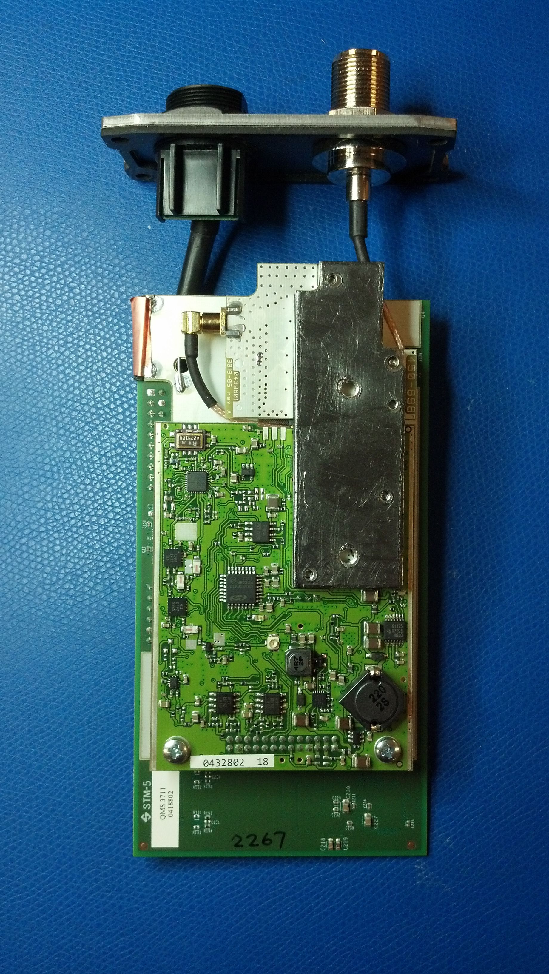
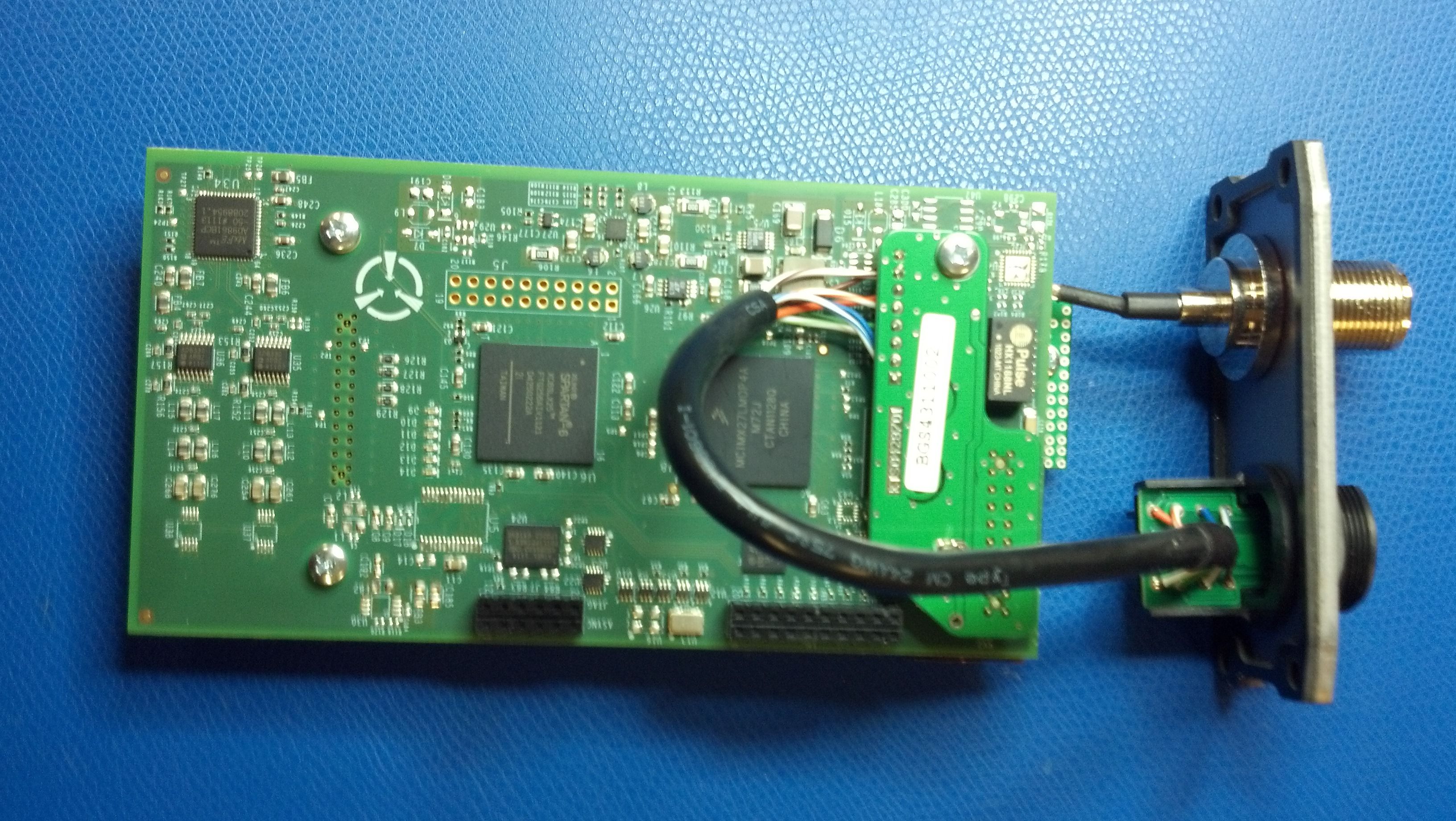
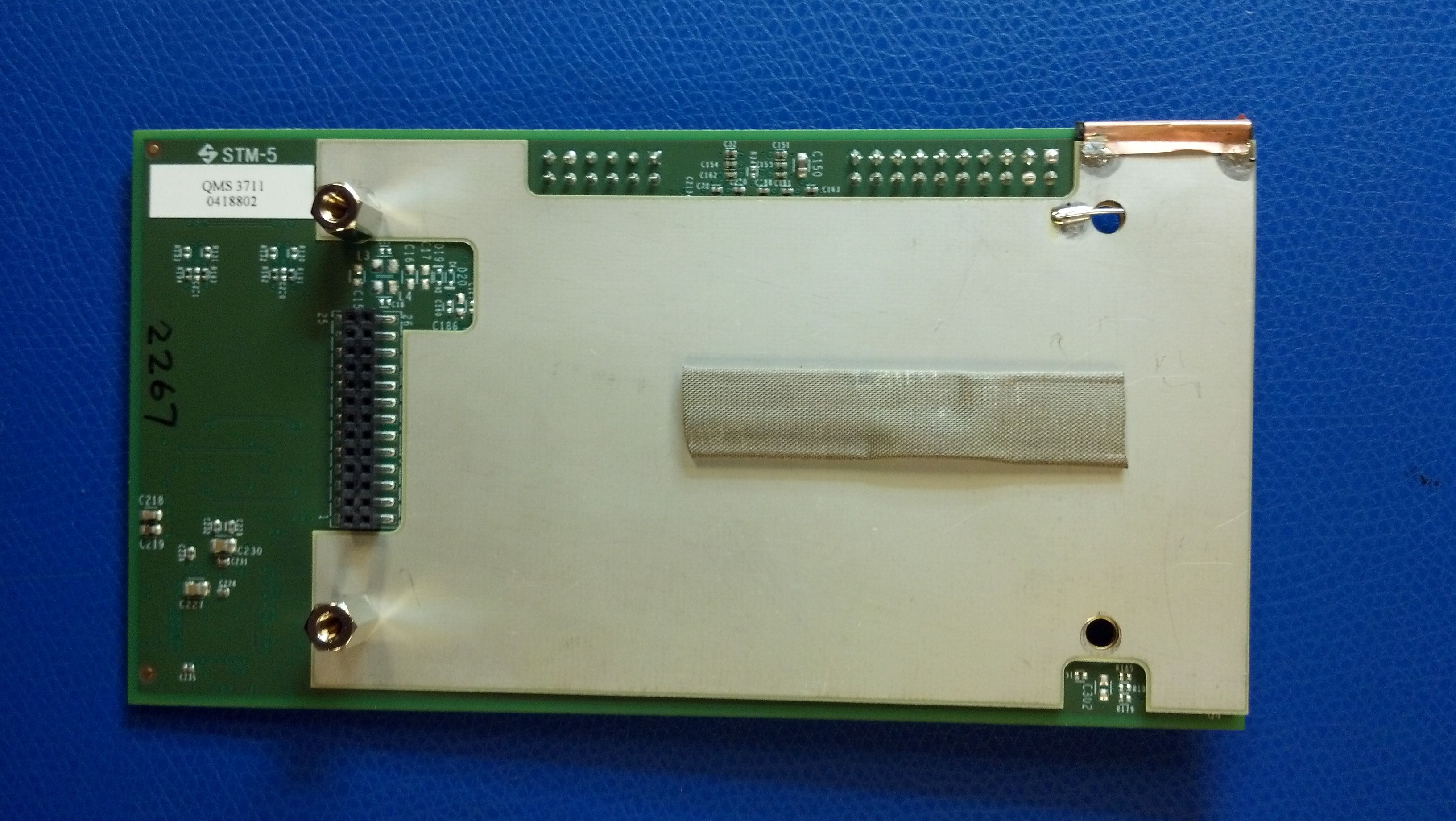
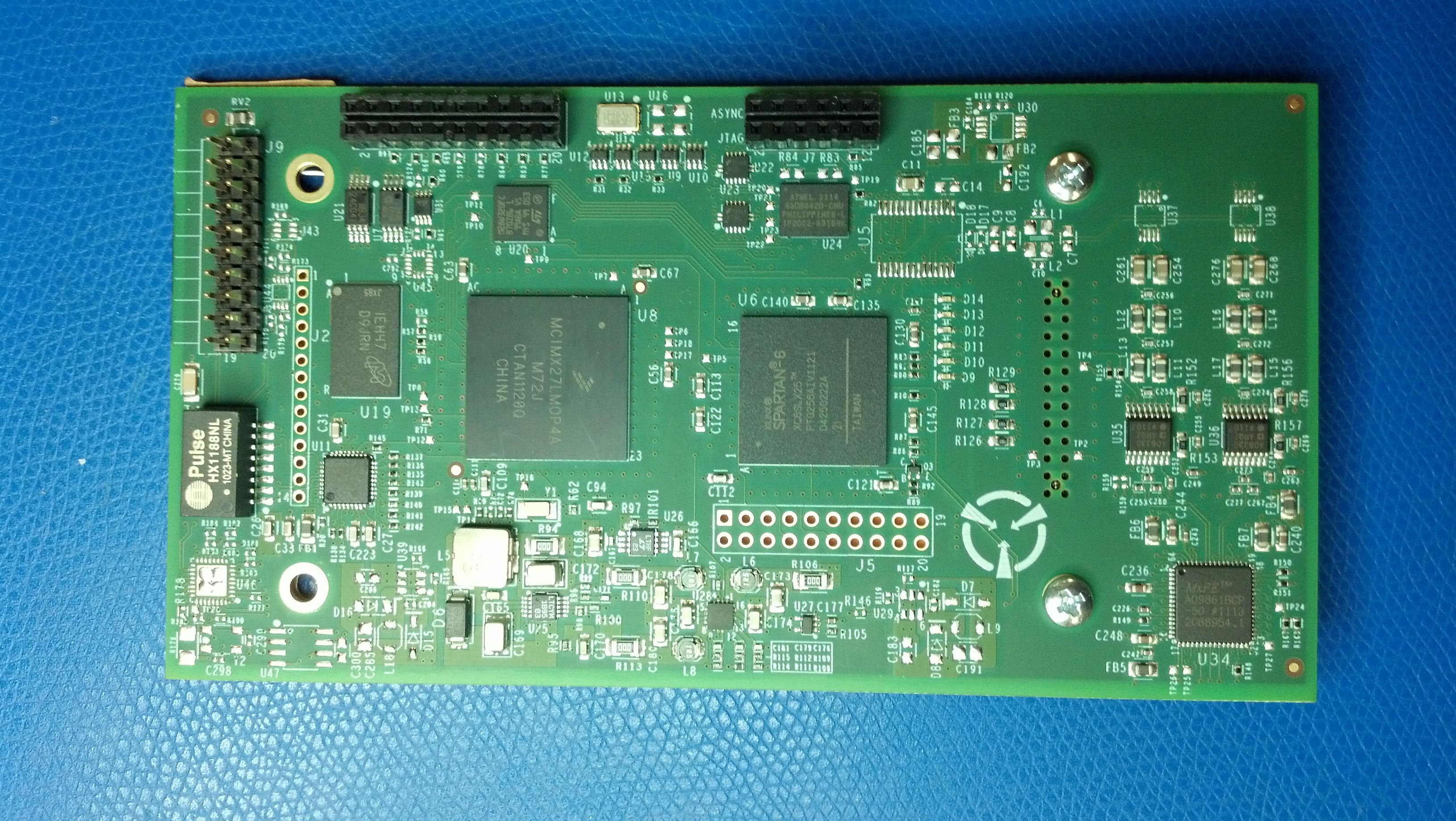
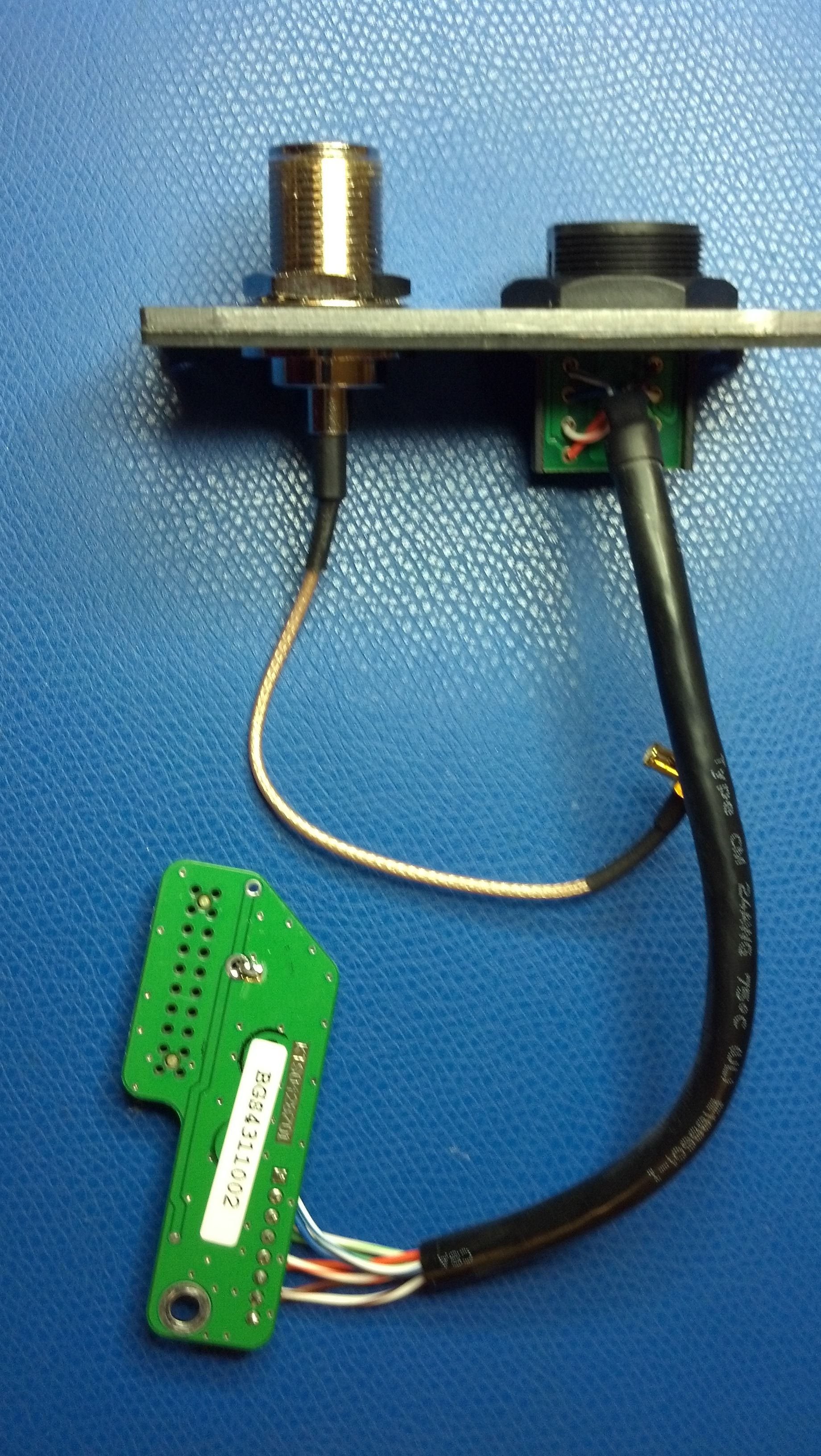
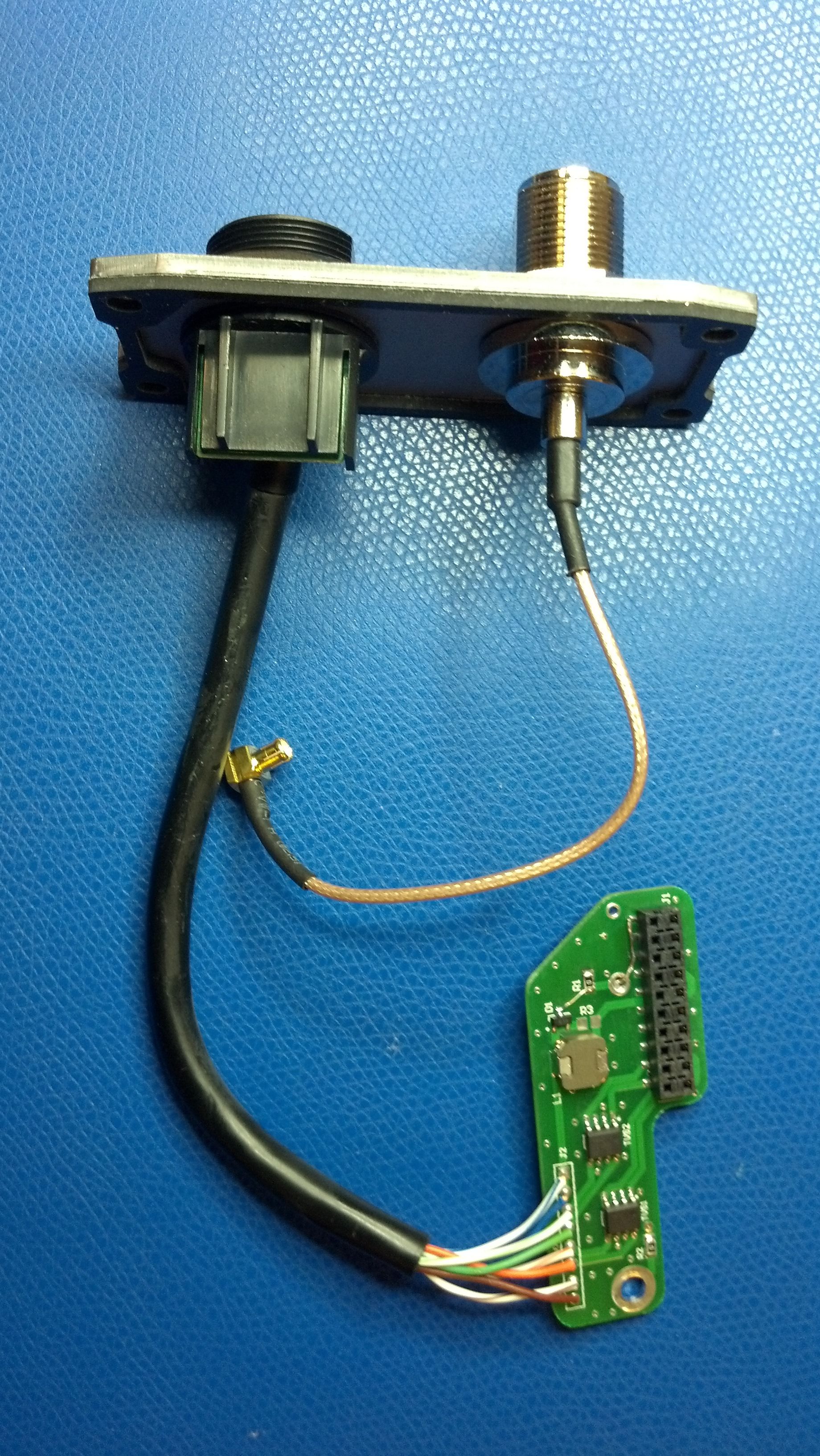
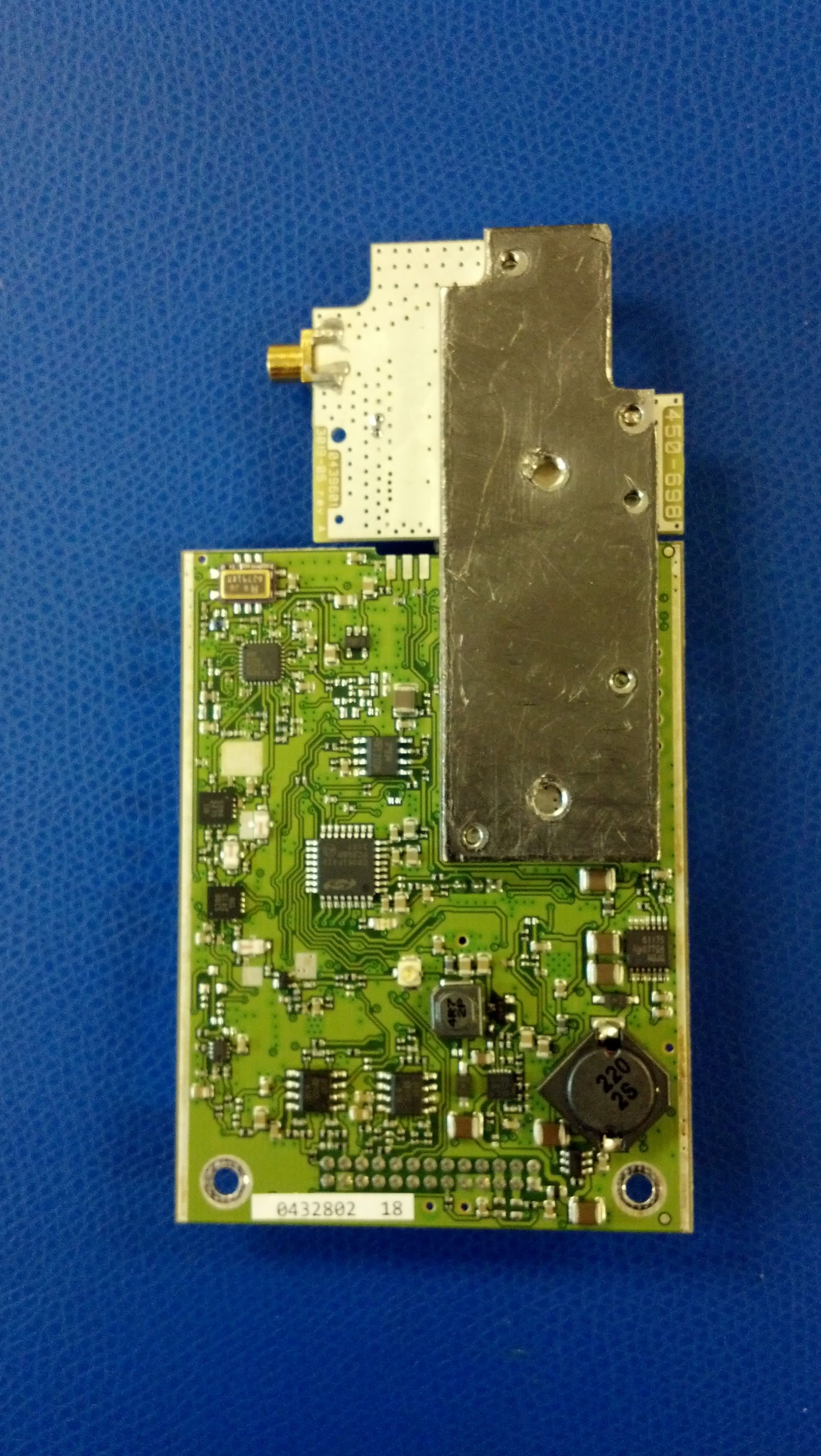
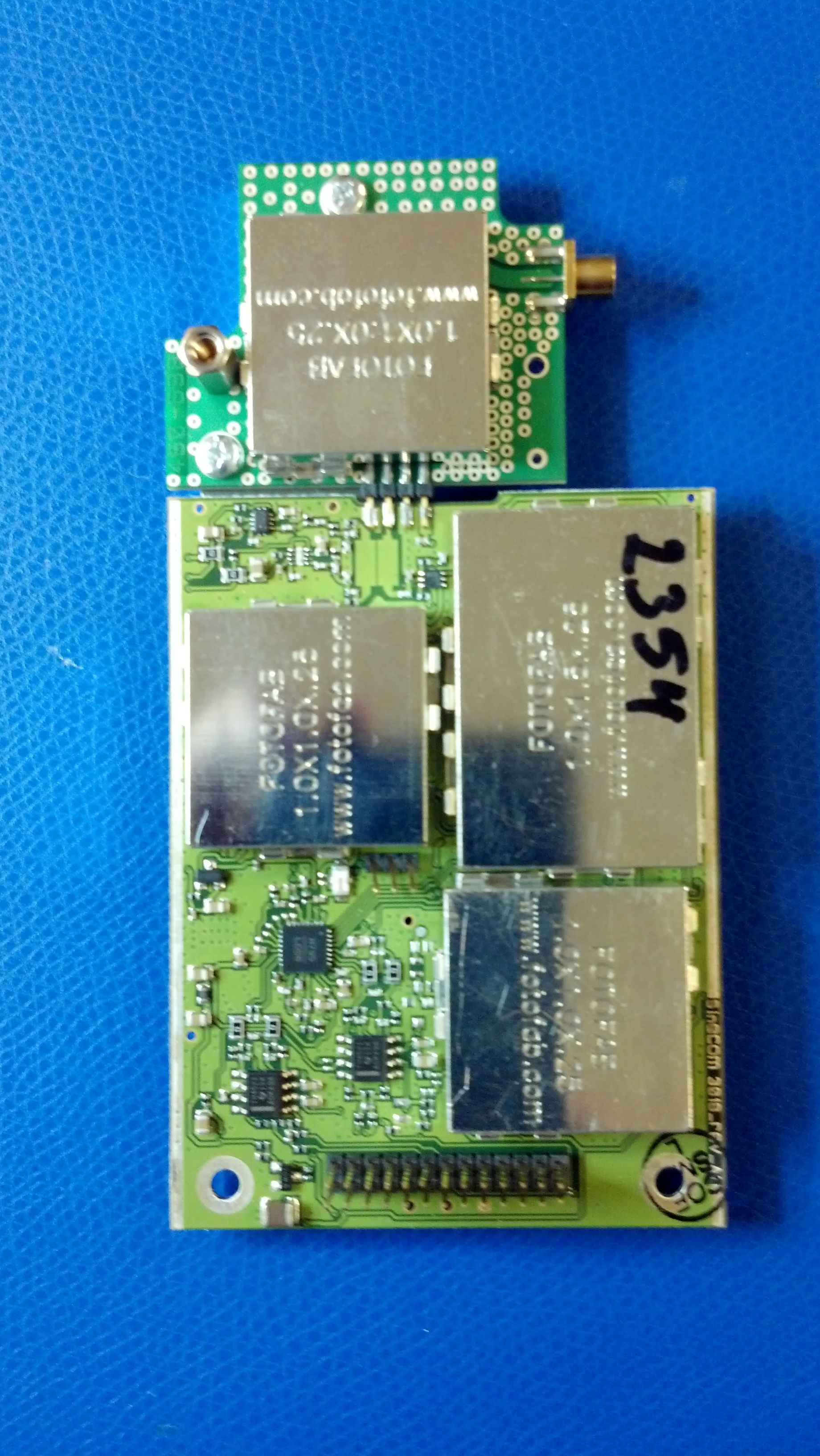
Document Text
Text extracted from the exhibit documents filed with the FCC. Open a document above to read the original.
Users Manual
1 Agility White Space Radio (AWR) Operator Manual Model Number AWR-US-U-100 June 2012 Revision A.12 2 Quick Start Procedure The KTS AWR White Space radio must be professionally installed by an authorized installer. The installer must be authorized by KTS Wireless. The installation must be in accordance with 47 CFR Part 15, Subpart H. Only the following components are approved for use with the radio. • Power Supply: APX Technologies SP63P924R • Antenna: Telex ALP-450 3 Install and configure Agility White Space Radio (AWR) as follows: 1. The AWR requires a 12-24 VDC input and consumes 6 Watts (RX) and 20 Watts (TX). Power is supplied via Power over Ethernet (PoE). External Interfaces –Ethernet (PoE) and Antenna Port 2. The AC power supply and PoE injector should be co-located in a weatherproof enclosure or environmentally controlled building. PoE Injector 4 3. Install the clamp on ferrite bead provided in the kit (Fair-rite part number 0446164281 or equivalent) 2.5 cm from the molded end of the Ethernet cable that plugs into the radio’s Ethernet port. 4. Connect a laptop and power supply to the AWR as shown. Failure to connect the PoE injector and power supply correctly can damage a connected device. Do not use a crossover terminated Ehternet cable. The AWR requires approximately 10 seconds to initialize. Set the computers IP Address to a static IP address on the same subnet as the AWR (e.g., 192.168.1.100). The default IP Address for new AWR radios is 192.168.1.4 with an IP Gateway address of 192.168.1.1. When the laptop and AWR are connected together and powered on, use the default IP Address to access and configure each new device prior to deployment using the EMS application. Each new AWR is preconfigured as a Spoke radio as shown on the Element Manager’s Device Info tab. All AWR’s destined to be network Hubs must have its Node Type changed to a Hub using the Node Type dropdown box. Select the desire node type and “save” the configuration to the radio using the EMS tool. The latitude and longitude where each radio is to be installed must be entered using the White Space tab. This information is provided to the White Space database so that the correct list of available channels can be sent to the radio. Note: The AWR should not be powered on without an antenna connected to the RF connector. 5. Installation of the EMS software provided with the AWR is required in order to manage the AWR devices. Insert the included CD into a computer and double click on the installation file: TVBD_Installer.exe. Follow the prompts to complete the EMS software installation process. The software installation process is described in detail in Section 4.0 TVBD Element Management System. 5 6. The mounting bracket, grounding cable and weather resistant RJ45 cap assembly is shown below. A thermal pad with adhesive is also included. Installing this thermal pad will reduce the operating temperature of the AWR, while maximizing performance and reliability. The bracket with thermal pad should be centered between the two screws located on the back of the radio. To connect the grounding cable, remove the nut and lock-washer from the AWR radio’s N-female RF connector and install the large ring-lug on the grounding cable over the N-female connector. Reinstall the lock-washer and nut. Tighten the nut securely. Remove one locknut from the mounting bracket U-bolt. Install the small ring-lug on the U-bolt and reinstall the locknut. Mounting Bracket Assembly and Weather Tight RJ45 cap Weather Tight Connector Assembly 6 Pole Mounted Configuration 7. Locate the coaxial cable used to connect the antenna. Each AWR is supplied with a three foot LMR- 400 coaxial cable with N-male connectors. If a longer cable is required, it should be a high quality, low-loss cable that is as short as possible. An in-line surge arrestor is recommended to prevent lightning strike damage to the radio. 7 8. After the installation process is complete and the EMS application is started, the Device Info screen will appear. Section 4.0 of this manual contains information regarding the use of the TVBD Element Management System (EMS). Reference Section 4.0 for details on configuring the AWR IP addresses. Note: The default IP address of the AWR is 192.168.1.4. TVBD EMS Main Screen 8 Table of Contents 1.0 Product Description .............................................................................................................................. 11 3.0 Specifications ........................................................................................................................................ 13 4.0 TVBD Element Management System .................................................................................................... 14 EMS Application Installation ................................................................................................................... 14 EMS Application User Guide ................................................................................................................... 21 Adding a Network ............................................................................................................................... 22 Adding Hub to the Network ............................................................................................................... 24 Adding a Spoke to a Hub .................................................................................................................... 27 Deleting a Node .................................................................................................................................. 29 Editing a Node .................................................................................................................................... 29 Saving the Network Configuration ..................................................................................................... 30 Save Radio Configuration .............................................…
Text truncated - open the document above for the full version.
Cover Letter(s)
a SPECTRUM EIFIItrIGiE JNIVf RSAL STECTRUM AC([55 *.*ffi' *$v*is{x Wireless Federal Communications Commission Eq uipment Authorization Branch 7435 Oakland Mills Rd Columbia, MD 21046 Ref.: FCC Equipment Certification Application -W Bands Database Certification December 26,2OLt Cover Letter Application for Equipment Authorization Database Conformance and Access Authorization The electronically submitted Form 731- Application for Equipment Authorization and supporting documentation is being submitted by KTS Wireless and Spectrum Bridge lnc. as a complete TV Whitespace system solution. Understanding that this is potentially one of the first submission of this type; the documentation being submitted is complete to the best of our knowledge and we are prepared to provide any additional documentation that is required upon reguest. KTS Wireless has developed a Part L5 Subpart H compliant fixed TVBD and seeks to initiate formal device certification testing of both the VHF (774-21.6MH2) and UHF {47O-7O0MHz) models of the Agile WhiteSpace Radio (AWR). The KTS radio conforms to the Spectrum Bridge, lnc., TV bands database API and the communication security methods used by the database. Spectrum Bridge lnc., an FCC designated TV bands database administrator, has designed and developed a Part 15 Subpart H compliant database. KTS Wireless has chosen Spectrum Bridge lnc. to certify the Fixed TVBD radio design. Spectrum Bridge seeks to provide evidence of rule compliance by which to initiate formal database certification testing, which includes radio and database interaction system testing. To permit database access during device certification testing, the FCC lD and serial number of the TVBD(s) under test must be enrolled in the Spectrum Bridge TV bands database. Additionally, until the database certification process is complete, Spectrum Bridge only allows restricted access to their TV bands database, controlled via source lP address filtering. The source lP address that will be used for any TVBD database query must be provided to Spectrum Bridge. ffispEcTnuM tr>f:gn I I3GiE: #2OO r Lake Mary. FL.866.598.7426 spectrumbridge.com 1064 Greenwood Blvd 7 #ffiFffiU ENABLING UNIVf *sAL SPECTRUM AC{[s$ Please provide the required FCC lDs, serial numbers, and source lP addresses to the Spectrum Bridge database administrator prior to commencing testing by email at [email protected], or by ca lling 4O7 -7 92-I57O. Sincerely, o, , I -:t-tr.lt, r,,lLlL* Larry Koos ,/' ., VP, Engineering Koos Technical Services, lnc. 1025 Greenwood Blvd # 391 Lake Mary, FL32745 Peter Stanforth Chief Technology Officer Spectrum Bridge, lnc. 1064 Greenwood Blvd #200 Lake Mary, FL32746 TSPECTNUM ST'-EIFI I trlGiE 1064 Greenwood Blvd#2OO o Lake Mary. FL.866.594.7426 spectnumbridge.com
Cover Letter(s)
SPECTRUM EtFlIIIGIE ENAELING UNIVERSAL SPECTRUM ACCEss Please provide the required FCC lDs, serial numbers, and source lP addresses to the Spectrum Bridge database administrator prior to commencing testing by email at [email protected], or by calling 4O7 -7 92-1570. Sincerely, o, t I f{ {1 ..1qt,r). . r,,lL,l b* Larry Koos ,/''. VP, Engineering Koos Technical Services, lnc. 1025 Greenwood Blvd # 391 Lake Mary, FL32746 Peter Stanforth Chief Tech nology Officer Spectrum Bridge, lnc. 1064 Greenwood Blvd #200 Lake Mary, FL32746 NSPEgTHUM ,$.'fEl Fr r trr GrE 1064 Greenwood Blvd #2OO r Lake Mary o FL.866.598.7426 spectrumbridge.com
RF Exposure Info
3998 FAU Blvd. Suite 310 Boca Raton, FL 33431 Tel: 561-961-5585 Fax: 561-961-5587 Certification Exhibit FCC ID: ZBGAWR2UHF FCC Rule Part: FCC 47 CFR 15 Subpart H ACS Project Number: 12-2110 Manufacturer: KTS WIRELESS Model: AWR-US-U-100 RF Exposure Model: AWR-US-U-100 FCC ID: ZBGAWR2UHF ACS Project: 11-2110 Advanced Compliance Solutions Page 2 General Information: Applicant: KTS Wireless ACS Project: 11-2110 Device Category: Mobile Environment: General Population/Uncontrolled Exposure Technical Information: Antenna Type: ALP-450 UHF Log Periodic Antenna Antenna Gain: 4.6 dBd Maximum Transmitter Conducted Power: 21.08 dBm Maximum System EIRP: 27.83 dBm, 606.74 mW Exposure Conditions: Greater than 20 centimeters MPE Calculation The Power Density (mW/cm 2 ) is calculated as follows: S = 2 4R PG π Where: S = power density (in appropriate units, e.g. mW/cm2) P = power input to the antenna (in appropriate units, e.g., mW) G = power gain of the antenna in the direction of interest relative to an isotropic radiator R = distance to the center of radiation of the antenna (appropriate units, e.g., cm) MPE Calculator for Mobile Equipment Limits for General Population/Uncontrolled Exposure* 47320.80.32120.236.754.732 200.113 58721.080.39128.236.754.732 200.121 69520.990.46125.606.754.732 200.118 Power Densit y (mW/cm^2) Distance (cm) Transmit Frequency (MHz) Radio Power (dBm) Power Density Limit (mW/Cm2) Radio Power (mW) Antenna Gain (dBi) Antenna Gain (mW eq.) Installation Guidelines The installation manual should contain text similar to the following advising how to install the equipment to maintain compliance with the FCC RF exposure requirements: RF Exposure In accordance with FCC requirements of human exposure to radio frequency fields, the radiating element shall be installed such that a minimum separation distance of 20 centimeters will be maintained. Conclusion This device complies with the MPE requirements by providing adequate separation between the device, any radiating structure and the general population.
Test Report
For The Scope of Accreditation Under Certificate Number AT-1533 3998 FAU Blvd. Suite 310 Boca Raton, FL 33431 Tel: 561-961-5585 Fax: 561-961-5587 EMI Test Report In Accordance with: FCC 47 CFR Part 15 Subpart B Authorization Type: Verification Manufacturer: KTS WIRELESS Model Covered: AWR-US-U-100 Model Variants: None Declared ACS Report: 11-2110.C01.1A Report Revision: A Report Issue Date: March 9, 2012 Project Manager: Reviewed by: Thierry Jean-Charles Sam Wismer EMC Engineer VP, Technology Advanced Compliance Solutions, Inc. Advanced Compliance Solutions, Inc. This report must not be used by the client to claim product certification, approval, or endorsement by ACLASS, ANSI, or any agency of the Federal Government. This test report shall not be reproduced except in full. This report may be reproduced in part with prior written consent of ACS, Inc. The results contained in this report are representative of the sample(s) submitted for evaluation. This report contains 23 pages REVISION HISTORY Report Number: 11-2110.C01.1A Manufacturer: KTS WIRELESS Model: AWR-US-U-100 DATE OLD REVISION NEW REVISION REASON PAGES AFFECTED APPROVED BY March 9, 2012 --- A Initial Release All Sam Wismer Project Information ACS Project: 11-2110.C01.1A Applicant Details Manufacturer: KTS WIRELESS Street Address: 1025 Greenwood Blvd. Suite 391 City, State/Province and Postal Code: Lake Mary FL, 32746 Country: USA Contact: Ed Gerhardt Phone: 407 260 0564 Fax: 407 333 3620 Email: [email protected] Sample Information Model: AWR-US-U-100 Model Variant(s): None Declared Product Description: The KTS Agility White Space Radio, AWR-US-U-100, is a White Space Fixed TVBD intentional radiator designed to operate on an unlicensed basis on available channels in the broadcast television frequency bands 470-599 MHz (TV channels 14-35) and 620-698 MHz (TV channels 39-51) Environment of Use: Residential Sample Receive Date: December 16, 2012 Sample Receive Condition: Good Test Mode Description: The unit was set to the receive mode. The unit was continuously communicating with a laptop PC which was also running a Jackhammer and Scrolling H software. Highest Data Rate: 1390 MHz Source: Receiver LO Power Interfaces (Check all that apply and enter power info): AC Mains Input 120VAC/60Hz AC Output N/A DC Input N/A DC Output N/A Battery N/A Other N/A I/O Interfaces: Interface Type Quantity Length (m) Shielded? See Section 3.2 Test Information Test Start Date: November 30, 2011 Test End Date: February 29, 2012 Emissions Pre-scan Site: SAC Final Emissions Site: SAC EMI Freq. Band: 30 MHz - 7 GHz Radiated Emissions Equipment Class: Class B Project Information(continued) ACS Project: 11-2110.C01.1A Test Methods/Standards Applied (Check all that apply): ANSI C63.4-2009 - American National Standard for Methods of Measurement of Radio-Noise Emissions from low-voltage electrical and electronic equipment in the range of 9kHz to 40 GHz. US Code of Federal Regulations (CFR): Title 47, Part 15, Radio Frequency Devices, Subpart B, Unintentional Radiators (2012) Industry Canada ICES-003 Issue 4: Digital Apparatus (February 2004). CISPR 16-2-1:2005 - Specification for radio disturbance and immunity measuring apparatus and methods Part 2-1: Methods of measurement of disturbances and immunity-Conducted Disturbance Measurement CISPR 16-2-3:2003 - Specification for radio disturbance and immunity measuring apparatus and methods Part 2-3: Methods of measurement of disturbances and immunity-Radiated Disturbance Measurement CISPR 22:2005 - Information technology equipment - Radio disturbance characteristics - Limits and methods of measurement EN 55022:2006 w/A1 - Information technology equipment - Radio disturbance characteristics - Limits and methods of measurement EN 55011:2007 w/A2- Industrial, scientific and medical (ISM) radio-frequency equipment - Electromagnetic disturbance characteristics - Limits and methods of measurement EN 61000-6-3:2007 Electromagnetic compatibility (EMC) - Part 6-3: Generic standards - Emission standard for residential, commercial and light-industrial environments EN 61000-6-4:2007 Electromagnetic compatibility (EMC) - Part 6-4: Generic standards - Emission standard for industrial environments AS/NZS CISPR 22:2006 - Information technology equipment - Radio disturbance characteristics - Limits and methods of measurement VCCI: V–2 & V-3/2009.04 – Agreement of Voluntary Control Council for Interference by Information Technology Equipment CNS 13438:2006 - CNS Limits and methods of measurement of radio interference characteristics of information technology equipment Table of Contents 1.0 INTRODUCTION..................................................................................................................................................6 1.1 SCOPE.................................................................................................................................................................6 1.2 PERFORMANCE CRITERIA...................................................................................................................................6 2.0 TEST FACILITIES & ENVIRONMENT.............................................................................................................7 2.1 TEST FACILITIES.................................................................................................................................................7 2.2 LABORATORY ACCREDITATIONS/RECOGNITIONS/CERTIFICATIONS..................................................................7 2.3 TEST ENVIRONMENT...........................................................................................................................................7 3.0 EQUIPMENT UNDER TEST (EUT)..................................................................................................................8 3.1 MANUFACTURER............................................................................................................................…
Text truncated - open the document above for the full version.
Test Report
3998 FAU Blvd. Suite 310 Boca Raton, FL 33431 Tel: 561-961-5585 Fax: 561-961-5587 Certification Test Report FCC ID: ZBGAWR2UHF FCC Rule Part: FCC 47 CFR 15 Subpart H ACS Report Number: 11-2110.W03.1A The test report contains data that are not covered within the scope of accreditation Manufacturer: KTS WIRELESS Model: AWR-US-U-100 Test Begin Date: November 30, 2011 Test End Date: February 29, 2012 Report Issue Date: March 7, 2012 FOR THE SCOPE OF ACCREDITATION UNDER CERTIFICATE NUMBER AT-1533 This report must not be used by the client to claim product certification, approval, or endorsement by ACLASS, ANSI, or any agency of the Federal Government. Project Manager: Reviewed by: Thierry Jean-Charles Kirby Munroe EMC Engineer Director, Wireless Certifications Advanced Compliance Solutions, Inc. Advanced Compliance Solutions, Inc. This test report shall not be reproduced except in full. This report may be reproduced in part with prior written consent of ACS, Inc. The results contained in this report are representative of the sample(s) submitted for evaluation. This report contains 27 pages 3998 FAU Blvd. Suite 310 Boca Raton, FL 33431 Tel: 561-961-5585 Fax: 561-961-5587 TABLE OF CONTENTS 1 GENERAL ...................................................................................................... 3 1.1 Purpose .............................................................................................................................................. 3 1.2 Product description .......................................................................................................................... 3 1.3 Test Methodology and Considerations ........................................................................................... 4 2 TEST FACILITIES .......................................................................................... 5 2.1 Location ............................................................................................................................................. 5 2.2 Radiated & Conducted Emissions Test Site Description .............................................................. 6 3 APPLICABLE STANDARD REFERENCES ................................................... 7 4 LIST OF TEST EQUIPMENT .......................................................................... 8 5 SUPPORT EQUIPMENT ................................................................................ 9 6 EQUIPMENT UNDER TEST SETUP BLOCK DIAGRAM .............................. 9 7 SUMMARY OF TESTS ................................................................................. 10 7.1 Antenna Requirement – FCC: Section 15.203 ............................................................................. 10 7.2 Power Line Conducted Emissions – FCC: Section 15.207 .......................................................... 10 7.3 Peak Output Power - FCC Section 15.709 (a) .............................................................................. 13 7.4 Adjacent Channel and Spurious Emissions - FCC 15.709 (c) ..................................................... 16 8 CONCLUSION .............................................................................................. 26 Model: AWR-US-U-100 FCC ID: ZBGAWR2UHF ACS Report: 11-2110.W03.1A Advanced Compliance Solutions Page 3 of 27 1 GENERAL 1.1 Purpose The purpose of this report is to demonstrate compliance with Part 15 Subpart H of the FCC’s Code of Federal Regulations. 1.2 Product description The KTS Agility White Space Radio, AWR-US-U-100, is a White Space Fixed TVBD intentional radiator designed to operate on an unlicensed basis on available channels in the broadcast television frequency bands 470-599 MHz (TV channels 14-35) and 620-698 MHz (TV channels 39-51). Technical Details Operating Range: 470 MHz – 698 MHz Number of Channels: 35 Channel Separation: 6 MHz Modulation: SOQPSK Supported Data Rates: 3.125 Mbps RF Connector: Type N Antenna Type/Gain: Telex ALP-450 UHF Log Periodic Antenna, 4.6 dBd Input Power: 12-24 VDC FPGA Code: v0xb CPU Firmware: 113 The radio is restricted from operating on channels 36, 37 and 38. The firmware in the radio restricts the use of these channels and they are not available for tuning. Additionally, the database restricts the use of these channels and does not include them in any channel lists. The users is unable to tune the radio independently of closed loop operation between the radio and database. Manufacturer Information: KTS Wireless 1025 Greenwood Blvd. Suite 391 Lake Mary FL, 32746 Contact: Ed Gerhardt Phone: 407 260 0564 FAX: 407 333 3620 Test Sample Serial Number(s): 2232 Test Sample Condition: Good Model: AWR-US-U-100 FCC ID: ZBGAWR2UHF ACS Report: 11-2110.W03.1A Advanced Compliance Solutions Page 4 of 27 1.3 Test Methodology and Considerations The AWR-US-U-100 was evaluated per the FCC KDB 416721 D01 White Space Test Procedures v01. The radiated emissions evaluation was performed for the EUT set in the orientation of typical installation. The evaluation was performed at the lower, middle and high channels of the frequency of operation up to the 10 th harmonic of the fundamental carrier. The RF conducted emissions evaluation was performed with the EUT output power adjusted to compensate for the antenna gain above 6 dBi. Power line conducted emissions was performed on the EUT set to the lower, middle and high channels of the frequency range of operation. The results are reported for the configuration leading to the highest emissions. The AWR-US-U-100 was programmed using the Spectrum Bridge TVBD Element Management System (EMS), Version 2.032. The programming tool configuration is provided below. Table 1.3-1 TVBD Element Management System Configuration TVBD Channel Frequency (MHz) Transmitter Control Transmit Power (dBm) RF Preset 14 473 21.5 6 33 587 21.5 6 35 599 21.5 6 39 623 21.5 6 51 695 21.0 6 Compliance to 602 MHz to 620 MHz band was investigated for the EUT tuned to 599 MHz and 623 MHz, respect…
Text truncated - open the document above for the full version.
Test Report
FCC PART 15.Subpart H White Spaces System TEST REPORT Fixed TVBD Device Part 2 Applicant Koos Technical Services, Inc. Address 1025 Greenwood Blvd. Lake Mary FL 32746 Model Number AWR-US-U-100. Product Description FIXED TVBD Database Administrator Spectrum Bridge Inc. Date Sample Received 3/6/2012 Date Tested 6 March 2012 Tested By Sushant Kadimdivan, John Day Approved By Sid Sanders Report Number 547UT12TestReport.doc Test Results PASS FAIL THE ATTACHED REPORT SHALL NOT BE REPRODUCED EXCEPT IN FULL WITHOUT THE WRITTEN APPROVAL OF TIMCO ENGINEERING, INC. 849 NW State Road 45 Newberry, FL 32669 USA Ph: 888.472.2424 or 352.472.5500 Fax: 352.472.2030 Email: [email protected] Website: www.timcoengr.com Testing Certificate # 0955-01 APPLICANT: Koos Technical Services, Inc. FCC ID: ZBGAWR2UHF REPORT: 547UT12 Page 2 of 28 TABLE OF CONTENT 1. GENERAL REMARKS ........................................................................................................................ 3 GENERAL INFORMATION ......................................................................................................................... 4 EMC EQUIPMENT LIST ............................................................................................................................ 6 TEST PROCEDURES ................................................................................................................................ 6 TEST CONFIGURATIONS: ......................................................................................................................... 7 Device and System Operation ................................................................................................................... 8 Test Network Configuration ...................................................................................................................... 8 TEST Summary ...................................................................................................................................... 10 III Test Result Summary ............................................................................................................................ 10 APPLICANT: Koos Technical Services, Inc. FCC ID: ZBGAWR2UHF REPORT: 547UT12 Page 3 of 28 GENERAL REMARKS The attached report shall not be reproduced except in full without the written permission of Timco Engineering Inc. The test results relate only to the items tested. Summary The device under test does: fulfill the general approval requirements as identified in this test report not fulfill the general approval requirements as identified in this test report Attestations The scope of this document is to report Fixed TVBD Part 2 Application and White Spaces System Test Report. There are three (3) components of the White Spaces technology; - TV Band devices (Fixed TVBD for Certification). - TV Bands Database (Spectrum Bridge Inc. certified WSDB services) - TV Band System, Made up of Fixed TVBD’s database, and layer of interaction between the devices and the databases. To the best of my knowledge and belief, these tests were performed using the measurement procedures described in this report. All instrumentation and accessories used to test products for compliance to the indicated standards are calibrated regularly in accordance with ISO 17025: 2005 requirements. I attest that the necessary measurements were made, under my supervision, at: Timco Engineering Inc. 849 NW State Road 45 Newberry, Fl 32669 Authorized Signatory Name: Testing Certificate # 0955-01 S. S. Sanders Compliance Engineer Date: March 16, 2012 APPLICANT: Koos Technical Services, Inc. FCC ID: ZBGAWR2UHF REPORT: 547UT12 Page 4 of 28 GENERAL INFORMATION DUT Description General: The Equipment Under Test (DUT’s), are Koos Technical Services, Inc. radios intended for use as Fixed Hub and Spoke equipment in a fixed White Spaces wireless network. For the purpose of testing and compliance with Part 15 Subpart H of Title 47 of the Code of Federal Regulations. The hub radio, named DUT1, operates as Fixed TV Band Device (TVBD) in Hub mode. The spoke radio, named DUT2, operates as Fixed TVBD in Spoke mode. The Koos Technical Services, Inc. radios are intentional radiators operating in the UHF bands. The radios tested are factory pre-configured UHF radios with an operating frequency range of 470- 599 MHz (TV channels 14-35) and 620-698 MHz (TV channels 39-51). The radios are used to create Point-to-Point (PTP), Point-to-Multipoint (PTM) or simplex (one-way) networks with priority routing support for voice, video and data traffic. Ethernet and RS-232 interfaces are available for user data traffic. The Agility Radio functions as a Fixed TVBD as defined in Section 15.703 of the FCC Rules. Local and remote network management is provided through a secure shell (SSH) network connection. Remote management is supported over the wireless link. Radios are managed with downloadable Element Management System software. DUT Specification: 1.0 Applicable Standard Part 15 Subpart H DUT Description Point-to-Point(PTP), Point-to-Multipoint(PTM) or simplex(one way) FCC ID ZBGAWR2UHF Application: Voice, Video and Data Traffic Support Programmable Data Rates: 3.125 Mbps Frequency Band: 470-599 MHz (TV channels 14-35) and 620-698 MHz (TV channels 39- 51). Bridged Ethernet Port: Wireless/Ethernet Ports IP Subnets Bridge Transmit Power(dBm): 21dBm Sensitivity (at 1E-3 BER) -118dBm @ 20Kbps; -97dBm @ 2Mbps APPLICANT: Koos Technical Services, Inc. FCC ID: ZBGAWR2UHF REPORT: 547UT12 Page 5 of 28 Test Facility Timco Engineering Inc. located at 849 NW State Road 45 Newberry, FL 32669 USA. Test Conditions Temperature: 26ºC Relative humidity: 50% Test Exercise The DUT was tested in normal end user mode, poll select operational mode Controls, Ports and Indicators: DUT Power Source 110–120Vac/50– 60Hz DC Power Battery Operated Exclusively Test Item Prototype Pre-Production Production Type of Equipment Fixed - WGF Mobile – WG1 Portable – WG2 Fixe…
Text truncated - open the document above for the full version.
Test Report
3998 FAU Blvd. Suite 310 Boca Raton, FL 33431 Tel: 561-961-5585 Fax: 561-961-5587 Certification Exhibit FCC ID: ZBGAWR2UHF FCC Rule Part: FCC 47 CFR 15 Subpart H ACS Project: 11-2110 Manufacturer: KTS WIRELESS Model: AWR-US-U-100 Radiated Emissions Test Plots (602MHz – 620MHz) Model: AWR-US-U-100 FCC ID: ZBGAWR2UHF ACS Project: 11-2110 Advanced Compliance Solutions Page 2 Figure 1: Radiated Emissions – TX = 599 MHz – Horizontal Polarization *Note: The plot corresponds to pre-scan measurements with a resolution …
Text truncated - open the document above for the full version.
Contact Information
Applicant
Ed Gerhardt(VP Operations)
Technical Contact
Koos Technical ServicesLarry Koos
[email protected]407-401-7042
1025 Greenwood Blvd · Lake Mary, Florida · United States
Test Firm
Advanced Compliance Solutions, IncRandy Abernathy
Technical Specifications
| # | Rule Parts | Frequency Range | Power Output | Emission | Tolerance |
|---|---|---|---|---|---|
| 1 | 15H | 473 MHz - 695 MHz | 128.00 mW | 6M00G1D | 1.0000000000 ppm |
Other Applications from Koos Technical Services, Inc

ZBG-ATRUHF-1
Apr 11, 2013UHF ATR
Equipment Class
TNB - Licensed Non-Broadcast Station Transmitter
ZBG-ATRVHF-1
Apr 07, 2013VHF ATR
Equipment Class
TNB - Licensed Non-Broadcast Station Transmitter
ZBG-ATRVHF-2
Apr 04, 2013VHF ATR
Equipment Class
TNB - Licensed Non-Broadcast Station Transmitter
ZBGAWR-1
Dec 21, 2011Fixed TVDB
Equipment Class
WGF - White Space Device with Geo-location- Fixed