ZBGAWR-1Fixed TVDB
Koos Technical Services, Inc
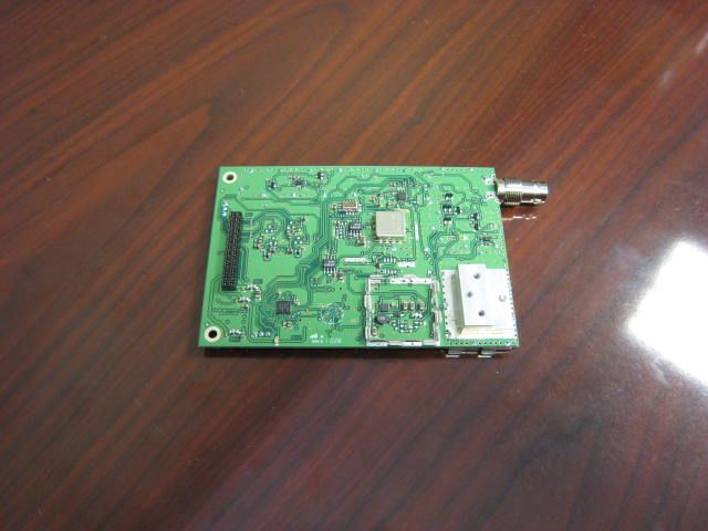
Click to zoom
Application Details
- Equipment Class
- WGF - White Space Device with Geo-location- Fixed
- Date of Grant
- Dec 21, 2011
- Application Purpose
- Original Equipment
- Date of Application
- Apr 24, 2011
- Equipment Note
- Fixed TVDB
- Frequency Range
- 177.00000000 - 213.00000000
- Company
- Koos Technical Services, Inc
- Country
- United States
Documents & Files
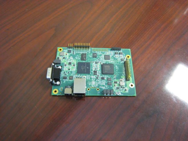
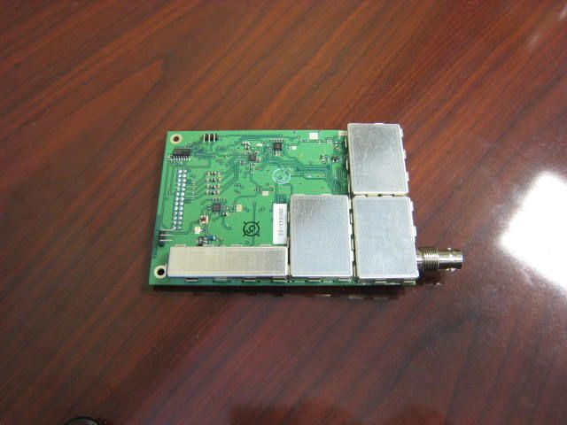
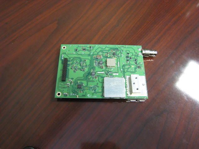
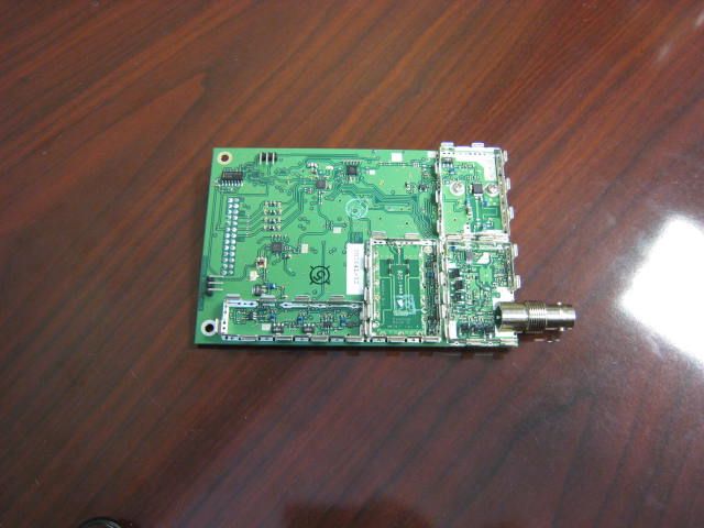
Document Text
Text extracted from the exhibit documents filed with the FCC. Open a document above to read the original.
Users Manual
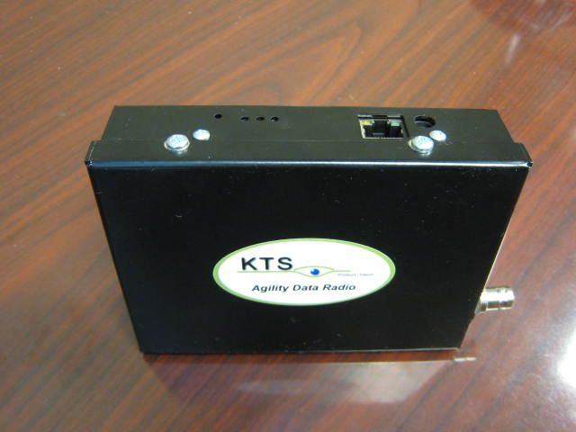
Agility White Space Radio (AWR) Operator Manual December 2011 Revision A.4 Quick Start Procedure Note: The KTS AWR White Space radio must be professionally installed. The installer must be authorized by KTS Wireless. This equipment has been tested and found to comply with the limits for a Class A digital device, pursuant to part 15 of the FCC Rules. These limits are designed to provide reasonable protection against harmful interference when the equipment is operated in a commercial environment. This equipment generates, uses, and can radiate radio frequency energy and, if not installed and used in accordance with the instruction manual, may cause harmful interference to radio communications or TV reception. Operation of this equipment in a residential area is strictly prohibited. If this device is installed within 250’ feet of a residential structure an RF engineer must be consulted to verify that the potential for interference has been mitigated. The KTS AWR White Space radio must be professionally installed by an authorized installer. Only the following components are approved for use with the radio. • Power Supply: SL Power PW173KB1203F01 with FAIR‐RITE clamp (0431167281) • Antenna: KTS Wireless VHF‐1, 7.5 dbi antenna Follow the steps below to install and configure Agility White Space Radio (AWR): 1. Select the location for the AWR. Must be an area free of water intrusion with a temperature range of ‐30 to +55 deg C (‐22 to 130 deg F). It is always best to use one of the mounting options shown below to provide adequate ‘heatsinking’ of the AWR case to a large metal surface. This will reduce the operating temperature of the AWR. L‐DIN Flat‐DIN Wall (with optional Fan) See the KTS website for ordering information. Correct mounting is required to maximizing AWR performance and reliability. 2. Locate the coaxial cable used to connect the antenna. This should be a high quality, low‐loss cable that is as short as possible. An in‐line surge arrestor to prevent lightning strike damage to the radio is recommended. 3. Locate the power source. The AWR requires a 9‐14 VDC input and draws about 1.5 A (when transmitting). Power is supplied via the 2.5 mm connector on the side of the unit (See Figure 1). 4. Connect the power supply cable to the AWR. Observe that the green power LED is illuminated. It takes about 7‐10 seconds for the AWR to boot‐up. After this, only the green power LED should be illuminated. TX/RX RF Activity Summary Fault Power (Blinks amber for (Red for fault) (Grn when Power on) TX and Grn for RX) 5. Connect a laptop to the AWR as shown in the Figure 2. Installation of the EMS software that was provided with the AWR will be required to manage the devices. Insert the CD in your computers CD drive and double click on the installation icon and follow the prompts to complete the EMS software installation process. TVBD_Installer.jar 6. After the installation process is complete and the EMS application is started, the Device Info screen will appear (See Figure 3, Section 4.0 of this manual contains the details of using the TVBD Element Management System (EMS). Reference Section 4.0 for details on configuring the EMS and resetting AWR IP addresses (i.e., changing from the default value). The default IP address of the AWR is 192.168.1.4. Note: Pressing and holding the recessed Reset button (See Figure 1) for at least 12 seconds will force the radio back to its default settings. Reset Button (recessed) LED Indicators Grn: Power Red: Sum Fault Amber/Grn: RF Tx/Rx Ethernet Port DC Power In (9-14 VDC/2.5 A) Serial Port Antenna (BNC) Figure 1: AWR Connections Figure 2: AWR/EMS Connection Figure 3: TVBD EMS Main Screen Position Color Function 1 Green Power On 2 Red Summary Fault 3 Green/Amber RF Activity (Amber = TX; Green=RX) Table 1: LED Definitions Contents 1.0 Product Description .................................................. 11 2.0 Applications .............................................................. 12 3.0 Specifications ............................................................ 14 4.0 AWR Element Management System ......................... 16 5.0 Upgrading Software .................................................. 44 Copyright Notice Copyright 2011, KTS Wireless, Inc, All rights reserved Operational and Safety Notices RF Exposure The radio described in this manual transmits RF energy. The concentrated energy from the antenna may pose a health hazard. All antennas used with this radio must be installed to provide a minimum separation from all persons of 90 cm (36 inches). The above separation distance must be maintained at all times. More information can be obtained from the FCC at the following website: http://www.fcc.gov/Bureaus/Engineering_Technology/Documents/bulletins/oet65/oet65.pdf FCC Part 15 Notice Equipment operation currently conforms to the rules for TV band devices, pursuant to Part 15 of the FCC Rules. These rules are designed to provide reasonable protection against harmful interference. This equipment generates, uses and can radiate radio frequency energy and, if not installed and used in accordance with the instructions, may cause harmful interference to radio communications. However, there is no guarantee that interference will not occur in a particular installation. If this equipment does cause harmful interference to radio or television reception, which can be determined by turning the equipment off and on, the operator is encouraged to try to correct the interference by one or more of the following measures: - Reorient or relocate the receiving antenna. - Increase the separation between the equipment and receiver. - Connect the equipment into an outlet on a circuit different from that to which the receiver is connected. - Consult the manufacturer, dealer or an experienced radio/ TV technician for help. This equipment has been tested and found to comply with the limits for a Class A digital device, pursuant to part 15 of the FCC Rules. These limits are des…
Text truncated - open the document above for the full version.
Cover Letter(s)
SPECTRUM i ^^fek_ tt^K idSSs*™ Product Vision Federal Communications Commission Equipment Authorization Branch 7435 Oakland Mills Rd Columbia, MD 21046 Ref.: FCC Equipment Certification Application -TV Bands Database Certification April 25,2011 Cover Letter Application for Equipment Authorization Database Conformance and Access Authorization The electronically submitted Form 731 Application for Equipment Authorization and supporting documentation is being submitted by KTS Wireless and Spectrum Bridge Inc. as a complete TV Whitespace system solution. Understanding that this is potentially the first submission of this type; the documentation being submitted is complete to the best of our knowledge and we are prepared to provide any additional documentation that is required upon request. KTS Wireless has developed a Part 15 Subpart H compliant fixed TVBD and seeks to initiate formal device certification testing of both the VHF (174-216MHz) and UHF (470-700MHz) models of the Agility Radio 1200. The KTS radio conforms to the Spectrum Bridge, Inc., TV bands database API and the communication security methods used by the database. Spectrum Bridge Inc., an FCC designated TV bands database administrator, has designed and developed a Part 15 Subpart H compliant database. KTS Wireless has chosen Spectrum Bridge Inc. to certify the Fixed TVBD radio design. Spectrum Bridge seeks to provide evidence of rule compliance by which to initiate formal database certification testing, which includes radio and database interaction system testing. To permit database access during device certification testing, the FCC ID and serial number of the TVBD(s) under test must be enrolled in the Spectrum Bridge TV bands database. Additionally, until the database certification process is complete. Spectrum Bridge only allows restricted access to their TV bands database, controlled via source IP address filtering. The source IP address that will be used for any TVBD database query must be provided to Spectrum Bridge. iSPECTRUM III 1064 Greenwood Blvd #200 * Lake Mary • FL • 866.598.7426 spedrumbridge.com SPECTRUM UMACC Product Vision Please provide the required FCC IDs, serial numbers, and source IP addresses to the Spectrum Bridge database administrator prior to commencing testing by email at [email protected]. or by calHng 407-792-1570. Sincerely, EdGer Director, Operations Koos Technical Services, Inc. 1025 Greenwood Blvd # 391 Lake Mary, FL 32746 Peter Stanforth Chief Technology Officer Spectrum Bridge, Inc. 1064 Greenwood Blvd #200 Lake Mary, FL 32746 .SPECTRUM 'BRIDGE 1064 Greenwood Bivd #200 • Lake Mary • FL • 866.598.7426 spectrumbridge.com
Cover Letter(s)
SPECTRUM Product Vision Federal Communications Commission Equipment Authorization Branch 7435 Oakland Mills Rd Columbia, MD 21046 Ref.: FCC Certification Application - KTS Fixed TV Bands Device Agility Radio 1200 March 27,2011 AGENCY AGREEMENT KTS Wireless has chosen Spectrum Bridge Inc. to be the database provider with which we are submitting to certify the Agility Radio 1200 Fixed TVBD radio design. I hereby appoint Mr. Peter Stanforth and all representatives of Spectrum Bridge, Inc. authority to represent and act on behalf of Koos Technical Services, Inc. in the submission of FCC Equipment Certification Application for our Agility Radio 1200. Sin EdGerftardt Director, Operations Koos Technical Services, Inc. 1025 Greenwood Blvd # 391 Lake Mary, FL 32746 Peter Stanforth Chief Technology Officer Spectrum Bridge, Inc. 1064 Greenwood Blvd #200 Lake Mary, FL 32746 SPECTRUM BRIDBE; 1064 Greenwood Blvd fSOO • Lake Mary • FL • 866.598.7426 spectrumbridge.com
ID Label/Location Info
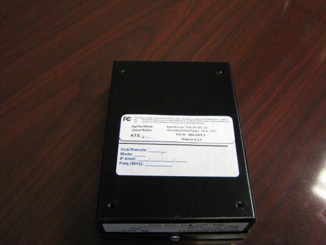
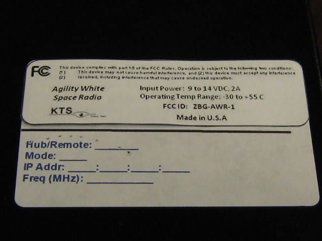
1 0 6 4 G r e e n w o o d B l v d # 2 0 0 • L a k e M a r y CERTIFICATION EXHIBIT B FCC Certification Application Code of Federal Regulations, Title 47, Part 15, Subpart H Applicant: Koos Technical Services, Inc. LABEL INFORMATION 1 0 6 4 G r e e n w o o d B l v d # 2 0 0 • L a k e M a r y • F L • 86 6 . 5 9 8 . 7 4 2 6 spectrumbridge.com ERTIFICATION EXHIBIT B FCC Certification Application – Fixed TV Bands Device Agility Radio 1200 Code of Federal Regulations, Title 47, Part 15, Subpart H Applicant: Koos Technical Services, Inc. LABEL INFORMATION 1 6 6 . 5 9 8 . 7 4 2 6 Fixed TV Bands Device Agility Radio 1200 Code of Federal Regulations, Title 47, Part 15, Subpart H
RF Exposure Info
Maximum Antenna gain 7.5 dBi Maximum RF Conducted Power 20dBm, Maximum EiRP: 27.5dBm, 562.3mW MPE Calculations P Transmit Power (mW): G Max Antenna Gain (dB): R Distance (cm): S Power Density (mW/cm Limits for General Public (mW/cm Adjust R until S < limits above Based on FCC OET Bulletin 65 RF Exposure Report Model ADR 1200 FCC ID ZBGAWR-1 7.5 dBi 20dBm, 100mW 27.5dBm, 562.3mW MPE Calculations 100.0 Max Antenna Gain (dB): 7.5 5.623413 Linear Gain 18 7.09 inches Power Density (mW/cm 2 ): 0.184 Limits for General Public (mW/cm 2 ): f = 30 - 300 MHz 0.2 f = 300 - 1500 MHz f/1500 Adjust R until S < limits above Based on FCC OET Bulletin 65 8/2/2011 Linear Gain inches
Test Report
White Spaces System Test Report Fixed TVBD Test Report Part 1 04/30/2011 Table of Contents Introduction ................................ Objective and Scope ................................ Definitions ................................ Equipment Manufacturer Information Database Administrator Information Equipment Under Test Information Test information ................................ 1. Equipment Under Test Description 1.1. General ................................ 1.1.1. Radio Specifications 1.2. Equipment Controls, Ports and Indicators 1.3. Testing and Supportive Hardware and Equipment 1.4. Testing Environment 1.5. Testing Configuration 1.5.1. List of Figures ................................ 1.5.2. Device and System Operation 1.5.3. Test Network Configuration 2. Tests Summary ................................ 2.1. Requirements Applicability Matrix 2.2. Fixed TV Bands Device Transmitter Tests 2.3. TV Bands System Tests ................................................................................................................................ ............................................................................................................................... ................................................................................................................................ Equipment Manufacturer Information................................................................................................ tor Information ................................................................................................ Equipment Under Test Information ................................................................................................ ................................................................................................................................ Equipment Under Test Description ............................................................................................... ................................................................................................................................ Radio Specifications ................................................................................................ Equipment Controls, Ports and Indicators ................................................................ Testing and Supportive Hardware and Equipment ............................................................... Testing Environment ................................................................................................ Testing Configurations. ................................................................................................ ................................................................................................ Device and System Operation ................................................................ Test Network Configuration ............................................................................................ ............................................................................................................................ Requirements Applicability Matrix ................................................................ Fixed TV Bands Device Transmitter Tests ................................................................ TV Bands System Tests – Fixed TVBD and TV Bands Database Interaction 2 ............................................ 3 ............................... 3 .............................................. 4 ................................... 6 ..................................... 6 ....................................... 6 ..................................... 7 ............................... 7 .................................. 7 .......................................... 7 ............................................ 8 ............................... 9 ............................................. 9 ......................................... 9 .................................................... 9 ......................................................... 11 ............................ 12 ............................ 13 ..................................................... 13 ........................................... 15 Fixed TVBD and TV Bands Database Interaction ........................ 16 Introduction Spectrum Bridge, Inc (SBI) develops software and services to build solutions addressing the global demand for wireless spectrum. SBI’s core technology empowers database solutions that increase availability, realization of this vision already has its place with the utilization of the newly released TV White Spaces spectrum. The company has positioned itself as a pioneer in the White Spaces technology dev and as a strong advocate for the timely acceptation and market adoption of the TV bands. Spectrum Bridge has developed Partnering with radio manufacturers, Bands Device (TVBD) and is the only enterprise with deployed trial networks under an experimental White Spaces license. As the FCC Chairman Julius Genachowski noted “... In Claudville, Va., they are providing broadband access to a remotely located elementary school. In Wilmington, N.C., they are trialing 'smart city' applications to manage traffic and monitor water quality at nearby wetlands. In Logan, Ohio, they are using the white space to deliver telemedicine to healthcare County, Calif., is utilizing 'smart grid' technologies for electricity networks. ...”. Objective and Scope The Federal Communications Commission (FCC) have set the course for the US to be the global technology leader by defining and governing the use of the TV White Spaces (TVWS) with the 2 revision and publication in the Code of Federal Regulations, Title 47, Part 15, Subpart H, effecti December 6, 2010. Spectrum Bridge acknowledges this achievement and for the recognition given by the Commissi approved TV White Spaces Database Administ The scope of this document is to combine Fixed TVBD Certification Application and White Spaces System…
Text truncated - open the document above for the full version.
Test Report
White Spaces System Test Report Fixed TVBD Test Report Part 2 04/30/2011 Contents 3. Test procedures and results 3.1 Cross Reference ................................ 3.2 Compliant Labeling ................................ 3.3 Fixed Device Transmitter Tests 3.3.1 Permissible Channels of Operation 3.3.2 Adjacent channel emissions at antenna connector 3.3.3 Beyond adjacent channel emissions at antenna connector 3.3.4 Power Spectral Density at antenna connector 3.3.5 Maximum output power at antenna connector 3.3.6 Transmit power control 3.3.7 RF Exposure ................................ 3.3.8 Conducted emissions at AC power input 3.3.9 Radiated emissions 3.3.10 Conducted emissions at antenna port 3.4 Fixed Device System Tests 3.4.1 TVBD initialization 3.4.2 Fixed TVBD registration 3.4.3 TVBD access security 3.4.4 Geo-location ................................ 3.4.5 Database access interval 3.4.6 Database access update 3.4.7 Available Channels 3.4.8 Display of Available Channels 3.4.9 TVBD ID Signal ................................ Test procedures and results ................................................................................................ ................................................................................................ ................................................................................................ Device Transmitter Tests ................................................................................................ Permissible Channels of Operation ................................................................ Adjacent channel emissions at antenna connector ................................ Beyond adjacent channel emissions at antenna connector ................................ Power Spectral Density at antenna connector ................................................................ Maximum output power at antenna connector ............................................................. Transmit power control ................................................................................................ ................................................................................................ Conducted emissions at AC power input ................................................................ Radiated emissions ................................................................................................ ed emissions at antenna port ................................................................ Fixed Device System Tests ................................................................................................ TVBD initialization ................................................................................................ TVBD registration ................................................................................................ TVBD access security ................................................................................................ ................................................................................................ access interval ................................................................................................ Database access update ................................................................................................ Available Channels ................................................................................................ Display of Available Channels ................................................................ ................................................................................................ 2 .......................................... 3 ........................................................ 3 ................................................... 3 ................................. 4 ................................................... 4 .......................................................... 7 ............................................. 7 ................................. 8 ............................. 10 .................................. 11 ..................................................... 11 ........................................ 12 ......................................... 12 ........................................ 13 ...................................... 13 ........................................... 13 ................................... 16 ....................................... 17 .................................................... 18 ................................. 18 .................................. 19 .......................................... 20 ......................................................... 21 ................................................. 21 3. Test procedures and results 3.1 Cross Reference Test Scope: Labeling Requirements Compliance: 47 CFR, Part 15, Subpart H (a) The provisions of Subparts A, B, and C of this part apply to TVBDs, exce (b) The requirements of subpart H apply only to the radio transmitter contained in the TVBD......., a TVBD that includes a receiver that tunes within the frequency range specified in §15.101(b) contains dig circuitry not directly associated with the radio transmitter is also subject to the requirements for unintentional radiators in subpart B. Test Procedure: 1. Verify complian Test Results: 1. Attached exhibits from provided for reference ( IQ5- Test Status: N/A 3.2 Compliant Labeling Test Scope: Labeling Requirements Compliance: 47 CFR, Part (a) In addition to the instructions furnished to the u statement........ Test Procedure: 1. Verify compliant labeling of the device 2. Verify compliant labeling in the Test procedures and results Labeling Requirements 47 CFR, Part 15, Subpart H, Section §15.705 The provisions of Subparts A, B, and C of this part apply to TVBDs, except where specific provisions are contained in subpart H. The requirements of subpart H apply only to the radio transmitter contained in the TVBD......., a TVBD that includes a receiver that tu…
Text truncated - open the document above for the full version.
Test Report
3998 FAU Blvd. Suite 310 Boca Raton, FL 33431 Tel: 561-961-5585 Fax: 561-961-5587 Certification Test Report FCC ID: ZBGAWR-1 FCC Rule Part: FCC 47 CFR 15 Subpart H ACS Report Number: 11-2056.W03.16.A Manufacturer: KTS WIRELESS Model: ADR 1200 Test Begin Date: June 25,2011 Test End Date: July 25, 2011 Report Issue Date: July 28, 2011 Project Manager: Reviewed by: Thierry Jean-Charles Kirby Munroe EMC Engineer Director, Wireless Certifications Advanced Compliance Solutions, Inc. Advanced Compliance Solutions, Inc. This test report shall not be reproduced except in full. This report may be reproduced in part with prior written consent of ACS, Inc. The results contained in this report are representative of the sample(s) submitted for evaluation. This report contains 27 pages 3998 FAU Blvd. Suite 310 Boca Raton, FL 33431 Tel: 561-961-5585 Fax: 561-961-5587 TABLE OF CONTENTS 1 GENERAL ...................................................................................................... 3 1.1 Purpose .............................................................................................................................................. 3 1.2 Product description .......................................................................................................................... 3 1.3 Test Methodology and Considerations ........................................................................................... 4 2 TEST FACILITIES .......................................................................................... 5 2.1 Location ............................................................................................................................................. 5 2.2 Radiated & Conducted Emissions Test Site Description .............................................................. 6 3 APPLICABLE STANDARD REFERENCES ................................................... 7 4 LIST OF TEST EQUIPMENT .......................................................................... 8 5 SUPPORT EQUIPMENT ................................................................................ 9 6 EQUIPMENT UNDER TEST SETUP BLOCK DIAGRAM .............................. 9 7 SUMMARY OF TESTS ................................................................................. 10 7.1 Antenna Requirement – FCC: Section 15.203 ............................................................................. 10 7.2 Power Line Conducted Emissions – FCC: Section 15.207 .......................................................... 10 7.3 Radiated Emissions – FCC: Section 15.109(Unintentional Radiation) ...................................... 12 7.4 Peak Output Power - FCC Section 15.709 (a) .............................................................................. 13 7.5 Adjacent Channel and Spurious Emissions - FCC 15.709 (c) ..................................................... 16 8 CONCLUSION .............................................................................................. 26 Model: ADR 1200 FCC ID: ZBGAWR-1 ACS Report: 11-2056.W03.16.A Advanced Compliance Solutions Page 3 of 27 1 GENERAL 1.1 Purpose The purpose of this report is to demonstrate compliance with Part 15 Subpart H of the FCC’s Code of Federal Regulations. 1.2 Product description The ADR 1200 is part of the KTS Wireless Agility Data Radio which operates in the VHF television band as a fixed TVBD. A wide variety of applications are supported including SCADA, Video Surveillance and broadband wireless Internet access. The radio may be used to create Point-to-Point (PTP), Point-to-Multipoint (PTM) or simplex (one-way) networks with priority routing support for voice, video and SCADA traffic. Local and remote network management is provided through a secure shell (SSH) network connection. Remote management is supported over the wireless link. Local management is provided through a PC-based Element Management System provided by KTS Wireless or an embedded client accessible with any Internet browser. The Ethernet port functions as a bridge for IP subnets via the wireless link Mode of Operation Frequency Range (MHz) Number of Channels Channel Separation (kHz) Data Rates Supported (kbps) SOQPSK 177 - 213 7 6000 3125 Manufacturer Information: KTS Wireless 1025 Greenwood Blvd. Suite 391 Lake Mary FL, 32746 Contact: Ed Gerhardt Phone: 407 260 0564 FAX: 407 333 3620 Test Sample Serial Number(s): 332 Test Sample Condition: Good Model: ADR 1200 FCC ID: ZBGAWR-1 ACS Report: 11-2056.W03.16.A Advanced Compliance Solutions Page 4 of 27 1.3 Test Methodology and Considerations The radiated emissions were performed on the EUT tested with a 7.5 dBi VHF antenna. The RF output power of the EUT had to be limited to 20 dBm in order to meet the power spectral density requirements. Radiated emissions were performed for the EUT set in three orthogonal orientations. Final measurements were performed using the orientation leading to the highest emissions. The serial port is not an active port per the customer. The radiated emissions were performed without a termination on the serial port per customer request. A FAIR-RITE (Model No.: 0431167281) ferrite clamp had to be added on the power supply cable to meet the unintentional radiated emissions requirements. Power line conducted emissions was performed on the EUT in both transmit and receive modes. Data is provided for the worst case configuration. TVBD Channel Frequency (MHz) Power (dBm) Modulation Data Rate (Mbps) 7 177 20 SOQPSK 3.125 10 195 20 SOQPSK 3.125 13 213 20 SOQPSK 3.125 Compliance to 602 MHz to 620 MHz band was investigated for the EUT tuned to 201 MHz and 207 MHz, respectively. Model: ADR 1200 FCC ID: ZBGAWR-1 ACS Report: 11-2056.W03.16.A Advanced Compliance Solutions Page 5 of 27 2 TEST FACILITIES 2.1 Location The radiated and conducted emissions test sites are located at the following address: Advanced Compliance Solutions, Inc. 3998 FAU Blvd, Suite 310 Boca Raton, Florida 33431 Phone: (561) 961-5585 Fax: (5…
Text truncated - open the document above for the full version.
Test Report
FCC Certification Application Applicant: Koos Technical Services, Inc. Power Limits Demonstration of Compliance for other FCC Certification Application – Fixed TV Bands Device, ADR Applicant: Koos Technical Services, Inc. Power Limits Supplementary Exhibit Compliance for other operational modes other than transmit ADR1200 r than continuous The following is submitted as with part 15.709, power limits for fixed TVBD continuous transmit. Low, mid and high channel TVBD operating range are provided. -70.00 -60.00 -50.00 -40.00 -30.00 -20.00 -10.00 0.00 10.00 20.00 172174 dBm Channel 7 (177MHz) +20dB transmit Power is submitted as supplemental data confirming compliance ower limits for fixed TVBD’s, in modes other than Low, mid and high channel examples within the are provided. Figure 1 –Channel 7 176178180182 MHz Channel 7 (177MHz) +20dB transmit Power data confirming compliance in modes other than within the Channel 7 (177MHz) +20dB transmit Power Poll Select Cont xmit Part 15H Mask 10.7 dBm PSD Limit…
Text truncated - open the document above for the full version.
Contact Information
Applicant
Ed Gerhardt(VP Operations)
Technical Contact
Koos Technical Services, IncLarry Koos
[email protected]407-401-7042
1025 Greenwood Blvd · Lake Mary, Florida · United States
Non-Technical Contact
Koos Technical Services, Inc.Ed Gerhardt
[email protected]407-401-7040
Test Firm
Advanced Compliance Solutions, Inc.Sam Wismer
[email protected]561-961-5585
Technical Specifications
| # | Rule Parts | Frequency Range | Power Output | Tolerance |
|---|---|---|---|---|
| 1 | 15H | 177 MHz - 213 MHz | 100.00 mW | ppm |
Other Applications from Koos Technical Services, Inc

ZBG-ATRUHF-1
Apr 11, 2013UHF ATR
Equipment Class
TNB - Licensed Non-Broadcast Station Transmitter
ZBG-ATRVHF-1
Apr 07, 2013VHF ATR
Equipment Class
TNB - Licensed Non-Broadcast Station Transmitter
ZBG-ATRVHF-2
Apr 04, 2013VHF ATR
Equipment Class
TNB - Licensed Non-Broadcast Station Transmitter
ZBGAWR2UHF
Jun 06, 2012White space radio controlled by database
Equipment Class
WGF - White Space Device with Geo-location- Fixed