ZBSPFES-1TNBREMOTE & MOBILE BLOOD GLUCOSE MONITORING AND DIABETES PATIENT FOLLOW-UP SYSTEM
Shenzhen New Element Medical Equipment Technology Development Co., Ltd.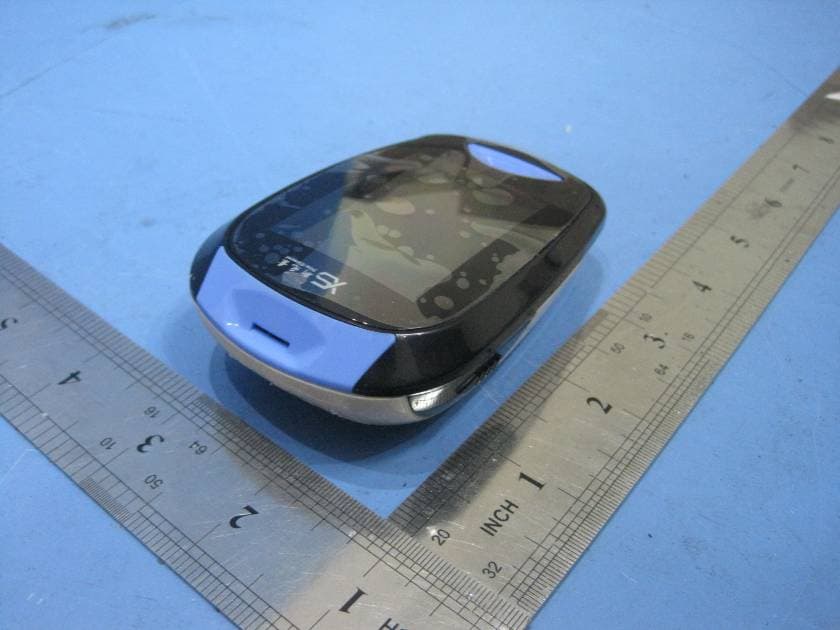
Click to zoom
Application Details
- Equipment Class
- DSS - Part 15 Spread Spectrum Transmitter
- Date of Grant
- Apr 17, 2011
- Application Purpose
- Original Equipment
- Date of Application
- Apr 17, 2011
- Equipment Note
- REMOTE & MOBILE BLOOD GLUCOSE MONITORING AND DIABETES PATIENT FOLLOW-UP SYSTEM
- Frequency Range
- 2402.00000000 - 2480.00000000
- Country
- China
Documents & Files
Document Text
Text extracted from the exhibit documents filed with the FCC. Open a document above to read the original.
Users Manual
I Remote & Mobile Blood Glucose Monitoring and Diabetes Patient Follow-Up System Table of Contents 1 Components ............................................................................................................. 1 2 Overview .................................................................................................................. 3 2.1 BG Monitoring Devices ................................................................................................ 3 2.1.1 BG Meter ............................................................................................................. 3 2.1.2 Sterile Lancet ..................................................................................................... 12 2.1.3 Lancing Device ................................................................................................... 13 2.1.4 Test Strip ........................................................................................................... 15 2.2 Health Mobile Phone ................................................................................................. 19 3 Measuring BG Value ............................................................................................... 22 3.1 Preparing for Obtaining a Blood Sample .................................................................... 22 II 3.2 Preparing the BG Meter ............................................................................................. 23 3.3 Starting Testing .......................................................................................................... 24 4 Operations on the Phone ...................................................................................... 27 4.1 Typing BG Value ......................................................................................................... 29 4.2 Viewing BG Trend ...................................................................................................... 31 4.3 Viewing Follow-Up Scheme ....................................................................................... 32 4.4 Viewing Health Advice ............................................................................................... 33 4.5 Complaint ................................................................................................................... 35 5 Precautions ............................................................................................................ 36 1 Remote & Mobile Blood Glucose Monitoring and Diabetes Patient Follow-Up System 1 Components Remote & Mobile Blood Glucose Monitoring and Diabetes Patient Follow-Up System collects daily blood glucose (BG) value by BG meter, and transmits the data to the health mobile phone via Bluetooth. Then, the mobile phone sends the data to the server through GPRS. A doctor remotely views the BG variation of a patient, and carries out timely treatment after analysis and diagnosis. The doctor can also interact with the patient through the server. The patient can view doctor advice on the mobile phone as well. The system consists of BG meter and software (software on health mobile phone and server). 2 3 Remote & Mobile Blood Glucose Monitoring and Diabetes Patient Follow-Up System 2 Overview 2.1 BG Monitoring Devices The BG monitoring devices can measure BG value anywhere and anytime, and transmit the data to health mobile phone via Bluetooth. The system consists of BG meter, lancing device, test strips and sterile lancet. 2.1.1 BG Meter The BG meter owns functions of data transmission and BG test. The following figure shows the structure of the BG meter, and Table 1 describes functions of each button. 4 Front Left side 1. Test slot 2. Bluetooth indicator 3. Display 4. Mode button 5. Test strip ejector 5 Remote & Mobile Blood Glucose Monitoring and Diabetes Patient Follow-Up System Back Right side 6. SET button 7. Battery compartment 8. Bluetooth button 6 Table 1 No. Name Function 1 Test slot Inserting the test strip 2 Bluetooth indicator Indicating data transmission and working status 3 Display Displaying the results, and symbols guiding your test 4 Mode button Turning on/off the meter; browsing and setting modes. 5 Test strip ejector Ejecting the used strip by pushing up this button. 6 SET button Entering and confirming the meter settings. 7 Remote & Mobile Blood Glucose Monitoring and Diabetes Patient Follow-Up System 7 Battery compartment Holding the batteries. AAA alkaline batteries only. 8 Bluetooth button Pushing up the button when the meter is off to enable the Bluetooth connection. Data collected by the BG meter are transmitted to the mobile phone when the meter is powered off. The Bluetooth indicator indicates the data transmission status. See Table 2. Table 2 No. Indicator Status Description 1 Off Bluetooth is disabled. 2 Flashing blue Bluetooth is enabled and 8 under connecting. 3 Normally on in blue Bluetooth connection is set up successfully. 2.1.11. Replacing Batteries If the battery symbol appears on the display, it means low battery. Please replace with two new AAA alkaline batteries. If the symbol begins to flash, it means the remaining power is not enough for a test. Replace batteries at No.7 Battery compartment in Figure 3.1. 1.Power off the BG meter. Press and then lift up the fibula to remove the cover. 2.Remove the used batteries, or pat the meter with your palm softly. Do not knock the meter with hard objects. 9 Remote & Mobile Blood Glucose Monitoring and Diabetes Patient Follow-Up System 3.Load two new AAA alkaline batteries. Make sure the anodes and cathodes of the batteries respectively point at the "+" and "-" symbols in the compartment. 4.Insert the two hinges of the compartment cover into the slots and press softly until they fit the fibula. Caution: Use AAA alkaline batteries only. Do not use rechargeable batteries. 2.1.12. Settings After loading batteries correctly, press the Mode button to start the meter. See the following figure and Tabl…
Text truncated - open the document above for the full version.
Cover Letter(s)
Shenzhen New Element Medical Equipment Technology Development CO.,Ltd. FCC ID:ZBSPFES-1TNB POWER OF ATTORNEY Mar.11,2011 Federal Communications Commission Authorization and Evaluation Division 7435 Oakland Mills Road Columbia, MD 21046 To Whom It May Concern: We, the undersigned, hereby authorize Waltek Services (ShenZhen) Co., Ltd. (Philo Zhong) on our behalf, to apply to the Federal Communications Commission on our equipment. Any and all acts carried out by Waltek Services (ShenZhen) Co., Ltd. (Philo Zhong) on our behalf shall have the same effect as acts of our own. This authorization expires on Mar.10,2012. This is to advise that we are in full compliance with the Anti-Drug Abuse Act. We, Shenzhen New Element Medical Equipment Technology Development CO.,Ltd., are not subject to a denial of federal benefits pursuant to Section 5301 of the Anti-Drug Act of 1988, 21 USC853a, and no party to the application is subject to a denial of federal benefits pursuant to that section. Sincerely, Shenzhen New Element Medical Equipment Technology Development CO.,Ltd. ------------------------------- Regulatory Affairs(Julia huang)
External Photos
Shenzhen New Element Medical Equipment Technology Development CO.,Ltd. FCC ID: ZBSPFES-1TNB Ref No.: WT11010218-D-E-F 17 Photographs - Constructional Details 17.1 EUT-Front View 17.2 EUT-Back View
ID Label/Location Info
Shenzhen New Element Medical Equipment Technology Development CO.,Ltd. FCC ID: ZBSPFES-1TNB Ref No.: WT11010218-D-E-F 18 FCC ID Label This device complies with Part 15 of the FCC Rules. Operation is subject to the following two conditions:(1)this device may not cause harmful interference,and (2) this device must accept any interference received, including interference that may cause undesired operation The Label must not be a stick-on paper. The Label on these products must be permanently affixed to the product and readily visible at the time of purchase and must last the expected lifetime of the equipment not be readily detachable. Proposed Label Location on EUT EUT Bottom View/proposed FCC Label Location FCC ID: ZBSPFES-1TNB This device complies with Part 15 of the FCC Rules. Operation is subject to the following two conditions:(1)this device may not cause harmful interference,and (2) this device must accept any interference received, including interference that may cause undesired operation
ID Label/Location Info
FCC ID Label Sample for Model: XYS.PFES-1TNB FCC ID: ZBSPFES-1TNB This device complies with Part 15 of the FCC Rules. Operation is subject to the following two conditions: (1) this device may not cause harmful interference, and (2) this device must accept any interference received, including interference that may cause undesired operation.
Internal Photos
2.1 PCB1-Front View 2.2 PCB1-Back View 2.3 PCB2-Front View 2.4 PCB2-Back View
Operational Description
Circuit Description After the installation of battery, the CPU starts the initialization and switches to the sleep state. Activate the collector in sleep state by pressing button 1 or inserting test strip. Then it switches to the measuring and viewing BG data mode. After CPU is working, all kinds of prompts are displayed on the LCD. The CPU uses external 8 MHz and 32.768 KHz crystal oscillator to work. Weak current signal generated by enzyme reaction on the test stripe can be transformed from AD to digital signals after being amplified. The CPU processes these signals and generates buzz prompt. Countdown information is displayed on the LCD. After the CPU finishes processing the signals, it generates measuring result and displays on the LCD. Meanwhile, BG data and time information are stored into the EEPROM. The collector switches to the sleep state. It can be activated by pressing button 1. Stored BG data can be invoked in order and displayed on the LCD. By pressing button 2 in the sleep state, the collector can be activated and switch to the system configuration mode. Then, you can set system time, BG unit, alarm, as well as deleting data. By pressing button 3 in the state of CPU shutting down, the collector can be activated and switch to the Bluetooth communication mode. The blue LED flashes. Bluetooth is enabled. The collector can communicate with other Bluetooth devices. COM 1 can communicate with PC by chip PWL transformation for debugging.
Schematics
1 1 2 2 3 3 4 4 5 5 6 6 7 7 8 8 DD CC BB AA Title NumberRevisionSize A3 Date:2011-2-15Sheet of File:C:\Documents and Settings\..\xuetangyi.SchDocDrawn By: P2.3 76 P1.7 80 P1.6 81 P1.5 82 P1.4 83 TA1 85 TD0/TD1 90 TD1/TCLK 91 TMS 92 TCK 93 RST/NMI 94 XIN 8 XOUT 9 P2.1 78 P3.2 69 P3.5 66 P3.6 65 A3 2 A4 3 A7 6 VREF+ 7 VeREF+ 10 VREF-/VeREF- 11 R33 59 R23 58 R13 57 R03 56 S14 26 S15 27 S16 28 S17 29 S18 30 S19 31 S20 32 S21 33 S22 34 S23 35 S24 36 S25 37 S26 38 S27 39 S28 40 S29 41 S30 42 S31 43 S32 44 S33 45 S34 46 S35 47 S36 48 S37 49 COM0 52 COM1 53 COM2 54 COM3 55 URXD0 74 UTXD0 75 AVSS 98 DXSS 99 AVCC 100 DVCC 1 BT2 STM32F105C8T6 P76 P81 P82 P83 P80 U4 3.0V TDO TDI TMS TCK nRST/NMI C15 CAP C14 CAP Y3 P78 P69 P66 P65 P2 P3 P6 P7 R28 R29 R30 S14 S15 S16 S17 S18 S19 S20 S21 S22 S23 S24 S25 S26 SDA SCL S29 S30 S31 BC4-RST BC4-RX BC4-TX UART2-TX UART2-RX POWER COM0 COM1 COM2 COM3 URXD0 UTXD1 JTAG X 14 Y 15 Z 4 X1 13 X0 12 Y1 1 Y0 2 A 11 B 10 C 9 INH 6 VEE 7 Z1 3 Z0 5 R21 R26 R27 - 1 + 2 out 3 AR1A - 4 + 5 out 6 AR1B R23 R19 R20 R22 R25 C24 C17 C12 C13 C16 P55 P56 P6 P6 blood blood P2 P3 BT3 BATTERY BT4 BATTERY D2 DIODE D3 DIODE D4 DIODE R32 VCC C1+ 1 V+ 2 C1- 3 C2+ 4 C2- 5 V- 6 T2OUT 7 R2IN 8 R2OUT 9 T2IN 10 T1IN 11 R1OUT 12 R1IN 13 T1OUT 14 GND 15 VCC 16 R24 C18 C20 C22 C23 C21 C19 1 2 4 3 S8 SW DIP-2 R31 3.0V P76 URXD0 UTXD1 VCC INOUT 2 3 1 S3 SW-SPDT 2 3 1 S4 SW-SPDT R11 R12 VCC BOOT0 BOOT1 1 2 +C3 C8C9C10 VCC C11 2 3 1 S2 SW-SPDT VDD VCC 1 2 J2 CON2 VCC VDD nRST TDI TMS TCK TDO RST 1 2 3 4 5 J1 PHONEJACK STEREO SW UART2-RX UART2-TX D1 KEY 1 2 3 4 5 6 7 8 9 J3 JTAG R11 R12 VCC3 UART-TX 1 UART-RX 2 UART-CTS 3 UART-RTS 4 PCM-CLK 5 PCM-OUT 6 PCM-IN 7 PCM-SYNC 8 AIO(0) 9 AIO(1) 10 RESET 11 3.3V 12 GND 13 GND 14 USB D- 15 SPI-C SB 16 SPI-M OSI 17 SPI-M ISO 18 SPI-C LK 19 USB D+ 20 GND 21 GND 22 PIO0 23 PIO1 24 PIO2 25 PIO3 26 PIO4 27 PIO5 28 PIO6 29 PIO7 30 PIO8 31 PIO9 32 PIO10 33 PIO11 34 Blue Tooth Model Antenna U2 BC4 A0 1 A1 2 A2 3 VSS 4 SDA 5 SCL 6 WP 7 VCC 8 24CXX U3 BC4-TX BC4-RX BC4-RST VCC SCL SDA CONNECT-STATE WORK-STATE AT-MODE R2 R1 VCC POWER R7 \ R9 R5 R10 LED2 12 R16 VCC ON/OFF C7 104 G 1 D 2 S 3 Q2 G 1 D 2 S 3 Q1 1 2 R15 1 2 R17 S14 S15 S16 R13 R14R18 VCC P81 P82 P83 S5 SW-PB S6 SW-PB S7 SW-PB Glucose Collector SCH V1.01/1 12 34 56 78 910 1112 1314 1516 1718 1920 2122 2324 2526 2728 2930 3132 3334 3536 3738 3940 P1 LCD VCC VCC S14 S15 S16 S17 S18 S19 S20 S21 S22 S23 S24 S25 COM0 COM1 COM2 COM3 P76 P81 P82 P83 P80 S29 S30 S31 P78 P69 P65 PIAR101 PIAR102 PIAR103 COAR1A PIAR104 PIAR105 PIAR106 COAR1B PIBT201 PIBT202 PIBT203 PIBT206 PIBT207 PIBT208 PIBT209 PIBT2010 PIBT2011 PIBT2026 PIBT2027 PIBT2028 PIBT2029 PIBT2030 PIBT2031 PIBT2032 PIBT2033 PIBT2034 PIBT2035 PIBT2036 PIBT2037 PIBT2038 PIBT2039 PIBT2040 PIBT2041 PIBT2042 PIBT2043 PIBT2044 PIBT2045 PIBT2046 PIBT2047 PIBT2048 PIBT2049 PIBT2052 PIBT2053 PIBT2054 PIBT2055 PIBT2056 PIBT2057 PIBT2058 PIBT2059 PIBT2065 PIBT2066 PIBT2069 PIBT2074 PIBT2075 PIBT2076 PIBT2078 PIBT2080 PIBT2081 PIBT2082 PIBT2083 PIBT2085 PIBT2090 PIBT2091 PIBT2092 PIBT2093 PIBT2094 PIBT2098 PIBT2099 PIBT20100 COBT2 PIBT301 PIBT302 COBT3 PIBT401PIBT402 COBT4 PIC301 PIC302 COC3 PIC701 PIC702 COC7 PIC801 PIC802 COC8 PIC901 PIC902 COC9 PIC1001 PIC1002 COC10 PIC1101 PIC1102 COC11 PIC1201PIC1202 COC12 PIC1301 PIC1302 COC13 PIC1401PIC1402 COC14 PIC1501PIC1502 COC15 PIC1601 PIC1602 COC16 PIC1701PIC1702 COC17 PIC1801PIC1802 COC18 PIC1901 PIC1902 COC19 PIC2001PIC2002 COC20 PIC2101 PIC2102 COC21 PIC2201PIC2202 COC22 PIC2301PIC2302 COC23 PIC2401 PIC2402 COC24 PID10APID10K COD1 PID201 PID202 COD2 PID301PID302 COD3 PID401 PID402 COD4 PIJ101 PIJ102 PIJ103 PIJ104 PIJ105 COJ1 PIJ201 PIJ202 COJ2 PIJ301 PIJ302 PIJ303 PIJ304 PIJ305 PIJ306 PIJ307 PIJ308 PIJ309 COJ3 PILED201 PILED202PILED203 COLED2 PIP101PIP102 PIP103PIP104 PIP105PIP106 PIP107PIP108 PIP109PIP1010 PIP1011PIP1012 PIP1013PIP1014 PIP1015PIP1016 PIP1017PIP1018 PIP1019PIP1020 PIP1021PIP1022 PIP1023PIP1024 PIP1025PIP1026 PIP1027PIP1028 PIP1029PIP1030 PIP1031PIP1032 PIP1033PIP1034 PIP1035PIP1036 PIP1037PIP1038 PIP1039PIP1040 COP1 PIQ101 PIQ102PIQ103 COQ1 PIQ201 PIQ202 PIQ203 COQ2 PIR101PIR102 COR1 PIR201 PIR202 COR2 PIR501 PIR502 COR5 PIR701PIR702 COR7 PIR901PIR902 COR9 PIR1001 PIR1002 COR10 PIR1101PIR1102 COR11 PIR1201PIR1202 COR12 PIR1301 PIR1302 COR13 PIR1401 PIR1402 COR14 PIR1501 PIR1502 COR15 PIR1601PIR1602 COR16 PIR1701 PIR1702 COR17 PIR1801 PIR1802 COR18 PIR1901PIR1902 COR19 PIR2001PIR2002 COR20 PIR2101 PIR2102 PIR2103PIR2104 PIR2105 PIR2106 PIR2107 PIR2109 PIR21010 PIR21011 PIR21012 PIR21013 PIR21014 PIR21015 COR21 PIR2201PIR2202 COR22 PIR2301PIR2302 COR23 PIR2401 PIR2402 PIR2403 PIR2404 PIR2405 PIR2406 PIR2407 PIR2408PIR2409 PIR24010 PIR24011 PIR24012 PIR24013 PIR24014 PIR24015 PIR24016 COR24 PIR2501PIR2502 COR25 PIR2601PIR2602 COR26 PIR2701 PIR2702 COR27 PIR2801PIR2802 COR28 PIR2901PIR2902 COR29 PIR3001PIR3002 COR30 PIR3101 PIR3102 COR31 PIR3201 PIR3202 COR32 PIS201 PIS202 PIS203 COS2 PIS301 PIS302 PIS303 COS3 PIS401 PIS402 PIS403 COS4 PIS501PIS502 COS5 PIS601PIS602 COS6 PIS701PIS702 COS7 PIS801 PIS802PIS803 PIS804 COS8 PIU201 PIU202 PIU203 PIU204 PIU205 PIU206 PIU207 PIU208 PIU209 PIU2010 PIU2011 PIU2012 PIU2013 PIU2014PIU2015PIU2016PIU2017PIU2018PIU2019PIU2020PIU2021 PIU2022 PIU2023 PIU2024 PIU2025 PIU2026 PIU2027 PIU2028 PIU2029 PIU2030 PIU2031 PIU2032 PIU2033 PIU2034 COU2 PIU301 PIU302 PIU303 PIU304PIU305 PIU306 PIU307 PIU308 COU3 PIU401 PIU402 COU4 PIY301 PIY302 COY3 PIBT201 PIBT20100 PIR3101 PIU2028 NLAT0MODE PIBT2044 PIU2011 NLBC40RST PIBT2045 PIU201 NLBC40RX PIBT2046 PIU202 NLBC40TX PIR1101 NLBOOT0 PIR1201 NLBOOT1 PIBT2052 PIP1031 NLCOM0 PIBT2053 PIP1027 NLCOM1 PIBT2054 PIP1040 NLCOM2 PIBT2055 PIP106 NLCOM3 PIU2032 NLCONNECT0STATE PIBT2010 PIBT2011 PIBT2056 PIBT2098 PIBT2099 PIBT302 PIBT402 PIC302 PIC702 PIC802PIC902PIC1002PIC1102 PIC1301 PIC1401 PIC1501 PIC1602 PIC1902 PIC2001 PIC2101 PIC2301 PIC2402 PID201 PIJ105 PIJ201 PIJ309 PILED203 PIP103 PIP1024 PIR1702 PIR2102 PIR2103 PIR2106 PIR2107 PIR2109 P…
Text truncated - open the document above for the full version.
Test Report
FCC TEST REPORT Waltek Services Ref No.: WT11020558-S-E-F Page 1 of 54 FCC ID : ZBSPFES-1TNB Applicant : Shenzhen New Element Medical Equipment Technology Development CO.,Ltd Adress of Applicant : 4F,Building 422,Bagua 4th Road,Futian District,Shenzhen,China Equipment Under Test (EUT) : Product description : Remote & Mobile Blood Glucose Monitoring and Diabetes Patient Follow-Up System Model No. : XYS.PFES-1TNB Standards : FCC 15 Subpart C Paragraph 15.247 Date of Test : Mar.09,2011 Test Engineer : Olic Huang /Engineer Reviewed By : Philo Zhong /Manager PERPARED BY: Waltek Services (Shenzhen) Co., Ltd. 1/F, Fukangtai Building,West Baima Rd.,Songgang Street, Baoan District, Shenzhen 518105,China Tel: +86-755-27553488 Fax: +86-755-27553868 Shenzhen New Element Medical Equipment Technology Development CO.,Ltd. FCC ID: ZBSPFES-1TNB Waltek Services Ref No.: WT11020558-S-E-F Page 2 of 54 2 Contents Page 1 COVER PAGE..........................................................................................................................................................1 2 CONTENTS ..............................................................................................................................................................2 3 TEST SUMMARY....................................................................................................................................................4 4 GENERAL INFORMATION..................................................................................................................................5 4.1 CLIENT INFORMATION............................................................................................................................................5 4.2 GENERAL DESCRIPTION OF E.U.T...........................................................................................................................5 4.3 DETAILS OF E.U.T. .................................................................................................................................................5 4.4 DESCRIPTION OF SUPPORT UNITS...........................................................................................................................5 4.5 STANDARDS APPLICABLE FOR TESTING..................................................................................................................5 4.6 TEST FACILITY........................................................................................................................................................6 4.7 TEST LOCATION......................................................................................................................................................6 5 EQUIPMENT USED DURING TEST ...................................................................................................................7 6 CONDUCTED EMISSION TEST ........................................................................................................................10 6.1 TEST EQUIPMENT..................................................................................................................................................10 6.2 TEST PROCEDURE.................................................................................................................................................10 6.3 CONDUCTED TEST SETUP.....................................................................................................................................11 6.4 EUT OPERATING CONDITION...............................................................................................................................11 6.5 CONDUCTED EMISSION LIMITS.............................................................................................................................12 6.6 CONDUCTED EMISSION TEST DATA......................................................................................................................12 7 RADIATION EMISSION TEST...........................................................................................................................13 7.1 TEST EQUIPMENT..................................................................................................................................................13 7.2 MEASUREMENT UNCERTAINTY.............................................................................................................................13 7.3 TEST PROCEDURE.................................................................................................................................................13 7.4 RADIATED TEST SETUP.........................................................................................................................................14 7.5 SPECTRUM ANALYZER SETUP...............................................................................................................................14 7.6 CORRECTED AMPLITUDE & MARGIN CALCULATION............................................................................................15 7.7 SUMMARY OF TEST RESULTS................................................................................................................................15 7.8 EUT OPERATING CONDITION...............................................................................................................................16 7.9 RADIATED EMISSIONS LIMIT.................................................................................................................................16 7.10 RADIATED EMISSIONS TEST RESULT................................................................................................................17 7.11 TEST CONDITION..............................................................................................................................................17 7.12 RADIATED EMISSION DATA.............................................................................................................................…
Text truncated - open the document above for the full version.
Test Setup Photos
Shenzhen New Element Medical Equipment Technology Development CO.,Ltd. FCC ID: ZBSPFES-1TNB Ref No.: WT11010218-D-E-F 16 Photographs of Testing Radiation Emission Test View For 30MHz-1000MHz Radiation Emission Test View For 1GHz-25GHz
Contact Information
Applicant
Julia Huang(Regulatory Affairs)
Test Firm
Waltek Services(Shenzhen) Co., Ltd.Philo zhong
Technical Specifications
| # | Rule Parts | Frequency Range | Power Output |
|---|---|---|---|
| 1 | 15C | 2.40 GHz - 2.48 GHz | 5.00 mW |
Other Applications from Shenzhen New Element Medical Equipment Technology Development Co., Ltd.
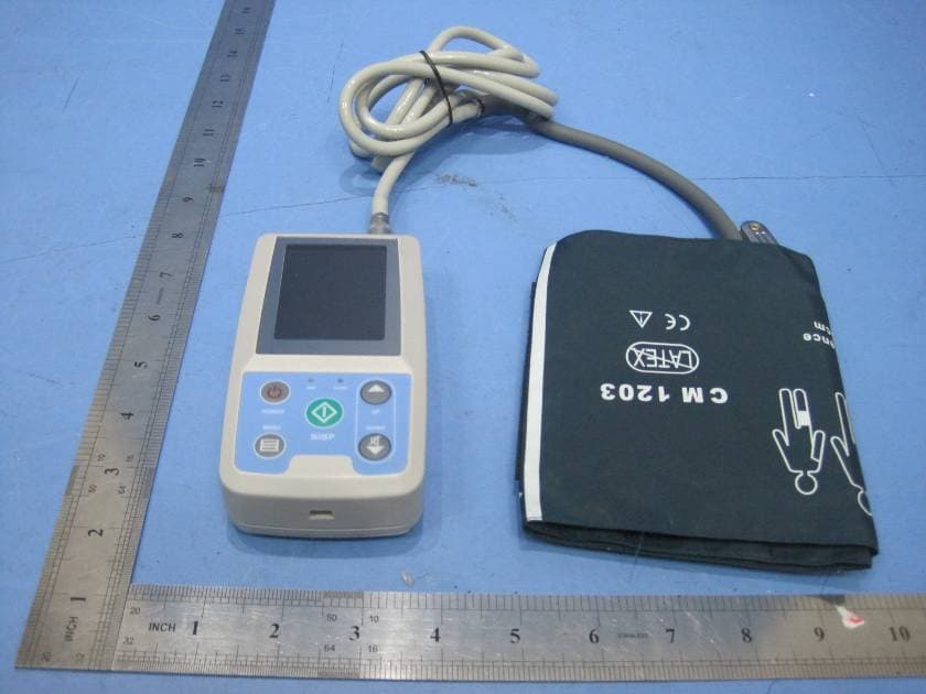
ZBSWRM-1XY
Mar 15, 2011REMOTE & MOBILE AMBULATORY BLOOD PRESSURE MONITORING SYSTEM
Equipment Class
DSS - Part 15 Spread Spectrum Transmitter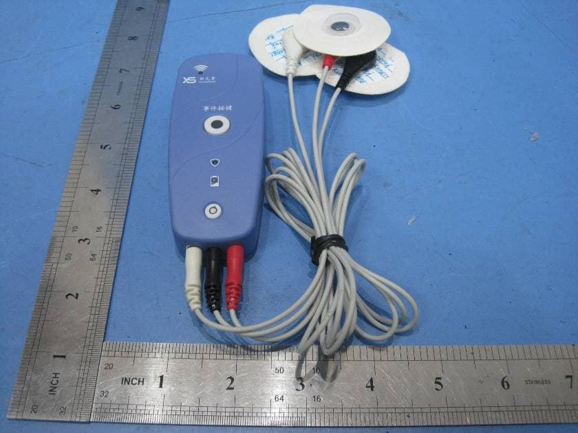
ZBSWRM-XE
Mar 14, 2011REMOTE & MOBILE ECG MONITORING SYSTEM
Equipment Class
DSS - Part 15 Spread Spectrum Transmitter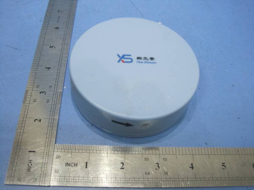
ZBSWRM-XPN
Mar 14, 2011REMOTE & MOBILE VOIDING DIARY MONITORING SYSTEM
Equipment Class
DSS - Part 15 Spread Spectrum Transmitter