ZBSWRM-1XYREMOTE & MOBILE AMBULATORY BLOOD PRESSURE MONITORING SYSTEM
Shenzhen New Element Medical Equipment Technology Development Co., Ltd.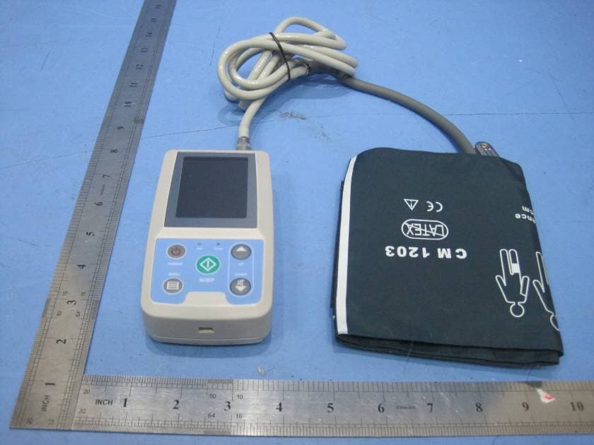
Click to zoom
Application Details
- Equipment Class
- DSS - Part 15 Spread Spectrum Transmitter
- Date of Grant
- Mar 15, 2011
- Application Purpose
- Original Equipment
- Date of Application
- Mar 15, 2011
- Equipment Note
- REMOTE & MOBILE AMBULATORY BLOOD PRESSURE MONITORING SYSTEM
- Frequency Range
- 2402.00000000 - 2480.00000000
- Country
- China
Documents & Files
Document Text
Text extracted from the exhibit documents filed with the FCC. Open a document above to read the original.
Users Manual
1 Table of Contents 1 Components........................................................... 2 2 Introduction ........................................................... 1 2.1 Blood Pressure Collector............................... 1 2.2 Cuff................................................................ 1 2.3 Health Mobile Phone ..................................... 1 3. Operations ............................................................ 5 3.1 Monitoring Blood Pressure ............................ 5 3.1.1 Installing Batteries ...................................... 5 3.1.2 Powering On ............................................... 6 3.1.3 Wearing the Cuff......................................... 1 3.1.4 Measuring Blood Pressure .......................... 2 3.2 Collecting Blood Pressure Data..................... 2 3.2.1 Message Bar................................................ 4 3.2.2 Data Section................................................ 4 3.2.3 Function Bar ............................................... 7 3.2.3.1 Interactive Message ......................... 7 3.2.3.2 Behavior Record .............................. 9 3.2.3.3 Data List......................................... 12 3.2.3.4 System Setting ............................... 14 3.3 Emergency Button....................................... 15 4 Cautions ................................................................. 1 2 1 Components Remote & Mobile Ambulatory Blood Pressure Monitoring System monitors the blood pressure and uploads data to the server through an e+Health mobile phone in real time. It provides doctors and nurses with real-time data, and uploads emergency events (including events generated by pressing the emergency button and events generated when the blood pressure exceeds preset alarm value) to the server for alarming. It consists of blood pressure collector, e+Health mobile phone and doctor workstation, as shown in Figure 1-1. 1 Figure 1-1 2 Introduction 2.1 Blood Pressure Collector Blood pressure collector is the terminal of collecting blood pressure data. It connects the mobile phone via Bluetooth. Data transmitted includes blood pressure data, control information and parameters. The appearance of the blood pressure collector is shown in Figure 2-1: BP collector Doctor workstation e+Health mobile phone 监护系统 Monitoring s ystem 2 Front: 9. USB port 8. NIBP air tube Side: 4. NIBP measurement button 1. Run indicator 7. Alarm indicator 3. Menu 2. Power button 6. Up 5. Down 13. MEAN 12. SYS 15. PR 14. DIA 3 Figure 2-1 Function and usage of each label and button are shown in Table 2-1: Ta b l e 2 - 1 No. Ty pe Name Function 1 Indicator RUN indicator The Run indicator flashes once every three seconds, indicating the collector is working. Rear: 10. Rear cover 11. Label 4 No. Ty pe Name Function 2 Button Power button Power switch of the blood pressure collector. Pressing and holding it for three seconds to power on. 3 Button Menu Pressing this button to execute the selected function. 4 Button Measuring button Pressing this button to inflate the cuff and measure blood pressure. Pressing the button to stop measuring and deflate the cuff during the measuring. 5 Button Down Button for selection. Pressing this button on main interface to pause alarming. Pressing it again to restore alarming. 6 Button Up Button for selection. 7 Indicator Alarm indicator The indicator flashes when alarm is generated during the measuring. 8 Other Air tube Connecting the cuff of the collector. 5 No. Ty pe Name Function 9 Other USB port Used to connect USB cable. 10 Other Battery cover One of the collector shelves. It is used to load and unload the batteries. 11 Other Label Product information. Remark: the No.9 USB port just for renew the programme in the factory, will not function to the users. 1 2.2 Cuff Cuff connects the upper arm of the user and blood pressure collector, as shown in Figure 2-2: Figure 2-2 1 2.3 Health Mobile Phone The health mobile phone obtains blood pressure data collected by the collector and upload data to the doctor workstation in real time. It can analyze and display data in user-defined period, and offer simple statistics and search. The phone can also receive interactive messages sent by the doctors, and transmit the parameters of blood pressure collector to the doctor workstation. The appearance of the health mobile phone is shown in Figure 2-3. 2 Figure 2-3 Function and usage of the health mobile phone keys are shown in Table 2-2. Ta b l e 2 - 2 No. Name Function 1 Dialing button To dial numbers. 2 Emergency Pressing this button when the ⑥ ① ② ⑤ ④ ③ Navigation button 3 No. Name Function button user feels uncomfortable to generate an emergency alarm, so the doctor can receive emergency information in time and give advice. 3 Navigation button OK or move upwards and downwards 4 e+Health Pressing this button to start the system and display the interface when the interface is hidden. 5 Hang-up Pressing this button to end the call or hide the interface. 6 e+Health shortcut icon Refer to the function of the e+Health button. Monitoring interface and functions of the health mobile phone are shown in Figure 2-4. 4 Figure 2-4 1. Message bar 2. Blood pressure: displaying all data (SBP, DBP, HR, MAP) measured at certain time 3. Curve chart: displaying data (SBP, DBP, HR, MAP) measured in certain period with curve chart. 4. Statistics: displaying statistics data in certain period (max. blood pressure, blood pressure load, DBP load, SBP load, HR). ② ③ ④ ① 5 3. Operations 3.1 Monitoring Blood Pressure 3.1.1 Installing Batteries The collector is powered by two AA alkaline batteries. Load two batteries to collector before using. (Note the positive and negative marks in the battery box.) 1. Press the rear cover lock to remove the rear cover. 2. Load the batteries correctly. 3. Put the rear cover back. Figure 3-1 Loading batteries Caution Unload the batteries when the collector is idle. 6 3.1.2 Powering On Press and hold the …
Text truncated - open the document above for the full version.
Block Diagram
STM32F103 VCT6 USB Port EEPROM 24C64 BUZZER 2.4" LCD KEY Blue Tooth Module Serial Flash 1MB x 8 DC/DC 500mA / 3.3V DC/DC 500mA / 5V Air Pump DC 3V Valve DC 3V Operational Ampllflers Press Sensor 32.768KHz 8MHz Standby Batt DC 3V Main Battery DC 3V STM32F103 C8T6 Standby Batt DC 3V EEPROM 24C256 32.768KHz 8MHz DC/DC 500mA / 3.3V UART UART I2C SPI ADC RTC I2C VDD_3.3V VDD 3.3V Ambulatory Blood Pressure Monitoring System ( XYS-WRM-1XY ) ANT
Cover Letter(s)
Shenzhen New Element Medical Equipment Technology Development CO.,Ltd. FCC ID:ZBSWRM-1XY POWER OF ATTORNEY Mar.11,2011 Federal Communications Commission Authorization and Evaluation Division 7435 Oakland Mills Road Columbia, MD 21046 To Whom It May Concern: We, the undersigned, hereby authorize Waltek Services (ShenZhen) Co., Ltd. (Philo Zhong) on our behalf, to apply to the Federal Communications Commission on our equipment. Any and all acts carried out by Waltek Services (ShenZhen) Co., Ltd. (Philo Zhong) on our behalf shall have the same effect as acts of our own. This authorization expires on Mar.10,2012. This is to advise that we are in full compliance with the Anti-Drug Abuse Act. We, Shenzhen New Element Medical Equipment Technology Development CO.,Ltd., are not subject to a denial of federal benefits pursuant to Section 5301 of the Anti-Drug Act of 1988, 21 USC853a, and no party to the application is subject to a denial of federal benefits pursuant to that section. Sincerely, Shenzhen New Element Medical Equipment Technology Development CO.,Ltd. ------------------------------- Regulatory Affairs(Julia huang)
External Photos
Shenzhen New Element Medical Equipment Technology Development CO.,Ltd. FCC ID: ZBSWRM-1XY Page 50 of 54 Ref No.: WT11020562-S-E-F 17 Photographs - Constructional Details 17.1 EUT-Front View 17.2 EUT-Back View
ID Label/Location Info
Shenzhen New Element Medical Equipment Technology Development CO.,Ltd. FCC ID: ZBSWRM-1XY Page 54 of 54 Ref No.: WT11020562-S-E-F 18 FCC ID Label This device complies with Part 15 of the FCC Rules. Operation is subject to the following two conditions:(1)this device may not cause harmful interference,and (2) this device must accept any interference received, including interference that may cause undesired operation The Label must not be a stick-on paper. The Label on these products must be permanently affixed to the product and readily visible at the time of purchase and must last the expected lifetime of the equipment not be readily detachable. Proposed Label Location on EUT EUT Bottom View/proposed FCC Label Location FCC ID: ZBSWRM-1XY This device complies with Part 15 of the FCC Rules. Operation is subject to the following two conditions:(1)this device may not cause harmful interference, and (2) this device must accept any interference received, including interference that may cause undesired operation
ID Label/Location Info
FCC ID Label Sample for Model: XYS.WRM-1XY FCC ID: ZBSWRM-1XY This device complies with Part 15 of the FCC Rules. Operation is subject to the following two conditions: (1) this device may not cause harmful interference, and (2) this device must accept any interference received, including interference that may cause undesired operation.
Internal Photos
Shenzhen New Element Medical Equipment Technology Development CO.,Ltd. FCC ID: ZBSWRM-1XY Page 52 of 54 Ref No.: WT11020562-S-E-F 17.5 PCB1-Front View 17.6 PCB1-Back View Shenzhen New Element Medical Equipment Technology Development CO.,Ltd. FCC ID: ZBSWRM-1XY Page 53 of 54 Ref No.: WT11020562-S-E-F 17.7 PCB2-Front View 17.8 PCB2-Back View
Operational Description
Circuit Description After the installation of battery, the CPU starts the initialization. BP monitoring interface is displayed on the LCD. It is in auto measuring mode and measures BP data automatically according to preset interval. If the preset time does not arrive, the CPU will cut off the power of measuring and viewing circuit, and switch to the sleep state. In sleep state, RTC inside the CPU keeps on working. The CPU is activated periodically and drives the LCD to flash to indicate that the whole machine is in the state of power on and monitoring. If the preset time arrives, the CPU switches to the working state. It powers on the measuring circuit, then drives bladder and solenoid valve to work. BP monitor begins to inflate the cuff. The pressure sensor inside BP monitor transforms BP change inducted by cuff to weak voltage signal. Then the signal is sent to AD transformer inside the CPU to transform into digital signal after being amplified by transmittal circuit. The CPU analyzes and processes pressure change; figures out BP data; displays values on the LCD, and then save them. After measuring, the CPU powers off the measuring circuit. BP data is transmitted to Bluetooth communication module by UART. Then the CPU switches to the sleep mode again. At this time, communication module turns on the power of Bluetooth module and requests for connection to matched mobile phone. BP data is uploaded to the mobile phone after connection. When the uploading is finished, the Bluetooth module is powered off. Communication module is in sleep mode until new measuring data are generated next time. At most cases, the CPU is in sleep state. When the preset time arrives or a user presses the manual measuring button, the CPU starts to work and enables measuring. Data are saved and uploaded after measuring. Then the CPU switches to the sleep state again. Press the power off button for a long time, the CPU will cancel the executing task. Then the collector is power off. The CPU uses external 8 MHz and 32.768 KHz crystal oscillator to work. 32.768 KHz crystal oscillator is the clock source of RTC inside CPU. Because RTC uses button battery as the auxiliary power supply, when the power is cut off in a short time, it can also keep the accuracy of RTC time, and ensure the normal running of the system.
Schematics
11 22 33 44 D D C C B B A A Title Number Revision Size A4 Date: 2011-2-14 Sheet of File: D:\ 公司 \..\WRM.1XY(SCH).01.SchDoc Drawn By: A0 1 A1 2 A2 3 GND 4 DATA 5 CLK 6 HOLD 7 VCC 8 24CXX U3 VBAT 1 PC13-ANTI_TAMP 2 PC14-OSC32_IN 3 PC15-OSC32_OUT 4 PD0 OSC_IN 5 PD1 OSC_OUT 6 NRST 7 VSSA 8 VDDA 9 PA0-WKUP 10 PA1 11 PA2 12 PA3 13 VSS_1 23 PA4 14 PA5 15 PA6 16 PA7 17 PB0 18 PB1 19 PB2 20 PB10 21 PB11 22 VDD_1 24 PB12 25 PB13 26 PB14 27 PB15 28 PA8 29 PA9 30 PA10 31 PA11 32 PA12 33 PA13 34 VSS_2 35 VDD_2 36 PA14 37 PA15 38 PB3 39 PB4 40 PB5 41 PB6 42 PB7 43 BOOT0 44 PB8 45 PB9 46 VSS_3 47 VDD_3 48 STM32F103-48P U1STM32F103C8 BET C1 Y1 8MHzY232.768KHz R4 3.3VCC C6 Vbat C2 OSC32inOSC32out OSCinOSCout OSC32inOSC32outOSCinOSCoutVbat 3.3VCC 3.3VCC 3.3VCC C8 C9 C10 3.3VCC C5 NRST NRST 3.3VCC SDASCL BT_TX BT_RX TXD1*RXD1* SDA SCL WKUP* RXD1TXD1 C3C4 C7 VIN JNTRST JTDO JTDI JTCK JTMS BOOT1 BT_RST BT_EN BOOT0 BOOT1BOOT0 JTAG MPU EEPROM R5 FB 1 LBI 2 /LBO 3 REF 4 /SHDN 5 GND 6 LX 7 OUT 8 U2 C11 C12 L1 C13 R1 R2 VIN LV* R3 3.3VCC 3.3VCC Q1 C14 C15 BT_VCC BT_EN 3.3VCC BT_AT BT_LINK BT_VCC BT_RXBT_TXBT_RSTBT_ATBT_LINK 1234567 J2 To Blue Tooth Module To Blood Pressure Module 12345678 J3 JNTRSTJTDIJTMSJTCKJTDONRST 3.3VCC D1 12345 J1 LV RXD3 TXD3 RXD3TXD3 RX3TX3 ADC_LV ADC_LV GND RP1 WKUP*RXD1*TXD1* RP2 BT_ATBT_LINK RP3 3.3VCC SCLSDA LV* LV R6R7 VIN Battery Voltage C16 Ambulatory Blood Pressure Monitoring System ( Model: XYS.WRM-1XY ) WRM.1XY(SCH).01 V1.0 POWER 11 22 33 44 D D C C B B A A Title Number Revision Size A4 Date: 2011-2-15 Sheet of File: D:\ 公司 \..\WRM.1XY(SCH).02.SchDoc Drawn By: UART_TX 1 UART_RX 2 UART_CTS 3 UART_RTS 4 PCM_CLK 5 PCM_OUT 6 PCM_IN 7 PCM_SYNC 8 AIO0 9 AIO1 10 RESETB 11 3.3 VCC 12 GND 13 GND 14 USB_- 15 SPI_CSB 16 SPI_MOSI 17 SPI_MISO 18 SPI_CLK 19 USB_+ 20 GND 21 GND 22 PIO0 23 PIO1 24 PIO2 25 PIO3 26 PIO4 27 PIO5 28 PIO6 29 PIO7 30 PIO8 31 PIO9 32 PIO10 33 PIO11 34 U1 HHW-S10 BT_VCC BT_TXBT_RXBT_RST BT_ATBT_LINK BT_VCC BT_RXBT_TXBT_RSTBT_ATBT_LINK 1234567 J1 C2103 C1104 BT_STA R1 1k LED1 Ambulatory Blood Pressure Monitoring System ( Model: XYS.WRM-1XY ) WRM.1XY(SCH).02 V1.0 Blue Tooth Module ANT 11 22 33 44 D D C C B B A A Title Number Revision Size A4 Date: 2011-2-14 Sheet of File: D:\ 公司 \..\WRM.1XY(SCH).03.SchDoc Drawn By: FB 1 LBI 2 /LBO 3 REF 4 /SHDN 5 GND 6 LX 7 OUT 8 U7 M2 R54 R75 L1 C27 C29 C28 5V C6 R17 U4 2.5V 123 456 U1 23 1 411 U3A 23 1 411 U5A 65 7 U3B 9 10 8 U3C 1312 14 U3D C2 C3 R4R3 2.5V R2 R1 R5 R6R7 R8R9 C1 R10 34K R11 12.4K 2.5V R12 R13 R14R15 R16 R20 R19 C5 C9 R18 R22 2.5V 65 7 U5B 9 10 8 U5C 1312 14 U5D R29 R30 R57 C10 R21 R24 R23 C11 R26 R27 R28 C12 PC5 Q7 R25 free PE13 23 1 411 U6A R34 123 456 U2 C17 VR1 65 7 U6B 9 10 8 U6C 1312 14 U6D C19 R32 R31R33 2.5V R36 R38 R35VR2 1K R37 R39 R41 C20 R40 2.5V R42R44 R45 VCC 1 D- 2 D+ 3 GND 4 GND 5 SHELL 6 SHELL 7 SHELL 8 SHELL 9 USB VS1 VS2 VS3 VS4 Z1Z2Z3 Z4 1 2 3 4 5 6 7 8 9 10 11 12 13 14 15 16 17 18 19 20 21 22 23 24 25 26 27 28 29 30 31 32 P2 BET1AA x 2 FB1 C24 P2-16 P2-1P2-7P2-5P2-11PE11PE13PC5PC4PC9 P2-4P2-6P2-10P2-12P2-14P2-22 3V M1 M5 C26 C25 3V* 3V* USB+ USB+ USB_D-USB_D+ USB_D-USB_D+ 3.3V VBET R52 3V R74 Q5 R53 /1R 1 1D 2 1CP 3 /1S 4 1Q 5 /1Q 6 GND 7 /2Q 8 2Q 9 /2S 10 2CP 11 2D 12 /2R 13 VCC 14 U9 R60 D01 3V R61 3.3V D02 R62C33 R76 Q9 R69 PE6PA5 PE6 PA5 Q6 R59 R58 R66 PE10 PE10 R78 R65 R77 L2 C30 Vin 3 Vout 2 1 GND U8 3V5V 5V C31 C32 Z6 C36 C37 4.5V 4.5V C35 3.3V C7 C8 2.5V BET2MS621F R56 D1 D2 VBET 3.3V USB POWER R68 R47 Q2 D4 C22 VALVE-1 3V V1 PE11 R49 R48 Q3 D5 C23 VALVE-2 3V V2 P2-1 R51 R50 Q4 P2-16 R67 R46 Q1 D3 C21 PUMP 3V P2-5 Q8R71 R70 PC9 R72 R73 C62 P2-22 M 4.5V4.5V 4.5V C18 4.5V P2-11 P2-7 PC4 C13 C4 CUFF PULSE 123 XY 12345 BT P2-12P2-10 R79 3.3V M4 P2-14 P2-4 P2-6 R64 M3 3.3V R63 3.3V Ambulatory Blood Pressure Monitoring System ( Model: XYS.WRM-1XY ) WRM.1XY(SCH).03 V1.0 11 22 33 44 D D C C B B A A Title Number Revision Size A4 Date: 2011-2-14 Sheet of File: D:\ 公司 \..\WRM.1XY(SCH).04.SchDoc Drawn By: PE2 1 PE3 2 PE4 3 PE5 4 PE6 5 VBAT 6 PC13-ANTI_TAMP 7 PC14-OSC32_IN 8 PC15-OSC32_OUT 9 VSS_5 10 VDD_5 11 OSC_IN 12 OSC_OUT 13 NRST 14 PC0 15 PC1 16 PC2 17 PC3 18 VSSA 19 VREF- 20 VREF+ 21 VDDA 22 PA0-WKUP 23 PA1 24 PA2 25 PA3 26 VSS_4 27 VDD_4 28 PA4 29 PA5 30 PA6 31 PA7 32 PC4 33 PC5 34 PB0 35 PB1 36 PB2 37 PE7 38 PE8 39 PE9 40 PE10 41 PE11 42 PE12 43 PE13 44 PE14 45 PE15 46 PB10 47 PB11 48 VSS_1 49 VDD_1 50 PB12 51 PB13 52 PB14 53 PB15 54 PD8 55 PD9 56 PD10 57 PD11 58 PD12 59 PD13 60 PD14 61 PD15 62 PC6 63 PC7 64 PC8 65 PC9 66 PA8 67 PA9 68 PA10 69 PA11 70 PA12 71 PA13 72 NC 73 VSS_2 74 VDD_2 75 PA14 76 PA15 77 PC10 78 PC11 79 PC12 80 PD0 81 PD1 82 PD2 83 PD3 84 PD4 85 PD5 86 PD6 87 PD7 88 PB3 89 PB4 90 PB5 91 PB6 92 PB7 93 BOOT0 94 PB8 95 PB9 96 PE0 97 PE1 98 VSS_3 99 VDD_3 100 U1 STM32F103VCT6 12 3 45 6 7 8 9 10 11 1213 14 U7 C6 Y2 8MHz Y3 32.768K C7 OSC32inOSC32out OSCinOSCout C1C2 A0 1 A1 2 A2 3 GND 4 DATA 5 CLK 6 HOLD 7 VCC 8 24CXX U3 3.3V SDASCL EEPROM R18R17 3.3V /S 1 Q 2 /W 3 GND 4 D 5 C 6 /HOLD 7 VCC 8 M25Pxx U9 CS1MISO MOSISLK DB00 1 DB01 2 DB02 3 DB03 4 GND 5 VDD 6 /CS 7 RS 8 /WD 9 /RD 10 NC 11 X+ 12 Y+ 13 X- 14 Y- 15 LED+A 16 LED-K1 17 LED-K2 18 LED-K3 19 LED-K4 20 NC 21 DB04 22 DB10 23 DB11 24 DB12 25 DB13 26 DB14 27 DB15 28 DB16 29 DB17 30 /RESET 31 VDD 32 VDD 33 GND 34 DB05 35 DB06 36 DB07 37 P1TFT_2.4" DB00DB01DB02DB03DB04DB05DB06DB07DB10DB11DB12DB13DB14DB15DB16DB17/CSRSWRRD R12 LCD_RST 1 2 3 4 5 6 7 8 9 10 11 12 13 14 15 16 17 18 19 20 21 22 23 24 25 26 27 28 29 30 31 32 P2 3.3V SCL SDA CS1 MISO 3.3V 3.3V HOLD HOLD SLK MOSI OSC32inOSC32outOSCinOSCout R27 Q6 Z8 3.3V Z3 C13 P2-16 M1 3.3V 3.3V R13 R23 3.3V PE7 PC7 3V 3V D04 FB 1 LBI 2 /LBO 3 REF 4 /SHDN 5 GND 6 LX 7 OUT 8 U4 L2 C11 C10 C12 R21 Q1 SPEAK 3.3V 3.3V R16 PB8 PB8 D02 C29 C30 C31 D03 3.3V 3.3V Vin 3 Vout 2 1 GND U8 USB+ PE1 PE1 R54R55 USB+ PE12 PE12 Z4Z5Z6 P2-16 P2-16 P2-1 P2-1P2-7 P2-7 R45R43 P2-5 P2-5 Z7 R44 PB9 PB9P2-16 P2-11 P2-11 PE15 PE15 PE11 PE11 PE13 PE13 PC5 PC5 PC4 PC4 R5 R10 C4 3.3V R7 R9 PE6 PE6 PA5 PA5 Z12 PC9 PC…
Text truncated - open the document above for the full version.
Test Report
FCC TEST REPORT Waltek Services Ref No.: WT11020562-S-E-F Page 1 of 49 FCC ID : ZBSWRM-1XY Applicant : Shenzhen New Element Medical Equipment Technology Development CO.,Ltd Adress of Applicant : 4F,Building 422,Bagua 4th Road,Futian District,Shenzhen,China Equipment Under Test (EUT) : Product description : Remote & Mobile Ambulatory Blood Pressure Monitoring System Model No. : XYS.WRM-1XY Standards : FCC 15 Subpart C Paragraph 15.247 Date of Test : Mar.09,2011 Test Engineer : Olic Huang /Engineer Reviewed By : Philo Zhong /Manager PERPARED BY: Waltek Services (Shenzhen) Co., Ltd. 1/F, Fukangtai Building,West Baima Rd.,Songgang Street, Baoan District, Shenzhen 518105,China Tel: +86-755-27553488 Fax: +86-755-27553868 Shenzhen New Element Medical Equipment Technology Development CO.,Ltd. FCC ID: ZBSWRM-1XY Waltek Services Ref No.: WT11020562-S-E-F Page 2 of 49 2 Contents Page 1 COVER PAGE..........................................................................................................................................................1 2 CONTENTS ..............................................................................................................................................................2 3 TEST SUMMARY....................................................................................................................................................4 4 GENERAL INFORMATION..................................................................................................................................5 4.1 CLIENT INFORMATION............................................................................................................................................5 4.2 GENERAL DESCRIPTION OF E.U.T...........................................................................................................................5 4.3 DETAILS OF E.U.T. .................................................................................................................................................5 4.4 DESCRIPTION OF SUPPORT UNITS...........................................................................................................................5 4.5 STANDARDS APPLICABLE FOR TESTING..................................................................................................................5 4.6 TEST FACILITY........................................................................................................................................................6 4.7 TEST LOCATION......................................................................................................................................................6 5 EQUIPMENT USED DURING TEST ...................................................................................................................7 6 CONDUCTED EMISSION TEST ........................................................................................................................10 6.1 TEST EQUIPMENT..................................................................................................................................................10 6.2 TEST PROCEDURE.................................................................................................................................................10 6.3 CONDUCTED TEST SETUP.....................................................................................................................................11 6.4 EUT OPERATING CONDITION...............................................................................................................................11 6.5 CONDUCTED EMISSION LIMITS.............................................................................................................................12 6.6 CONDUCTED EMISSION TEST DATA......................................................................................................................12 7 RADIATION EMISSION TEST...........................................................................................................................13 7.1 TEST EQUIPMENT..................................................................................................................................................13 7.2 MEASUREMENT UNCERTAINTY.............................................................................................................................13 7.3 TEST PROCEDURE.................................................................................................................................................13 7.4 RADIATED TEST SETUP.........................................................................................................................................14 7.5 SPECTRUM ANALYZER SETUP...............................................................................................................................14 7.6 CORRECTED AMPLITUDE & MARGIN CALCULATION............................................................................................15 7.7 SUMMARY OF TEST RESULTS................................................................................................................................15 7.8 EUT OPERATING CONDITION...............................................................................................................................16 7.9 RADIATED EMISSIONS LIMIT.................................................................................................................................16 7.10 RADIATED EMISSIONS TEST RESULT................................................................................................................17 7.11 TEST CONDITION..............................................................................................................................................17 7.12 RADIATED EMISSION DATA.............................................................................................................................18 7.12.1 Test mode: cont…
Text truncated - open the document above for the full version.
Test Setup Photos
Shenzhen New Element Medical Equipment Technology Development CO.,Ltd. FCC ID: ZBSWRM-1XY Page 49 of 54 Ref No.: WT11020562-S-E-F 16 Photographs of Testing Radiation Emission Test View For 30MHz-1000MHz Radiation Emission Test View For 1GHz-25GHz
Contact Information
Applicant
Julia Huang(Regulatory Affairs)
Test Firm
Waltek Services(Shenzhen) Co., Ltd.Philo zhong
Technical Specifications
| # | Rule Parts | Frequency Range | Power Output |
|---|---|---|---|
| 1 | 15C | 2.40 GHz - 2.48 GHz | 7.00 mW |
Other Applications from Shenzhen New Element Medical Equipment Technology Development Co., Ltd.
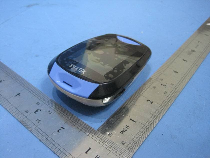
ZBSPFES-1TNB
Apr 17, 2011REMOTE & MOBILE BLOOD GLUCOSE MONITORING AND DIABETES PATIENT FOLLOW-UP SYSTEM
Equipment Class
DSS - Part 15 Spread Spectrum Transmitter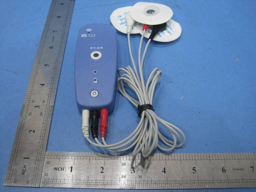
ZBSWRM-XE
Mar 14, 2011REMOTE & MOBILE ECG MONITORING SYSTEM
Equipment Class
DSS - Part 15 Spread Spectrum Transmitter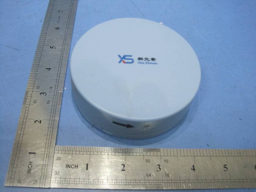
ZBSWRM-XPN
Mar 14, 2011REMOTE & MOBILE VOIDING DIARY MONITORING SYSTEM
Equipment Class
DSS - Part 15 Spread Spectrum Transmitter