ZBSWRM-XEREMOTE & MOBILE ECG MONITORING SYSTEM
Shenzhen New Element Medical Equipment Technology Development Co., Ltd.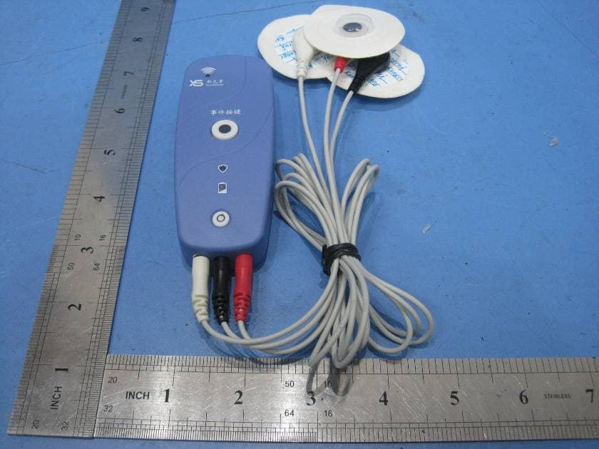
Click to zoom
Application Details
- Equipment Class
- DSS - Part 15 Spread Spectrum Transmitter
- Date of Grant
- Mar 14, 2011
- Application Purpose
- Original Equipment
- Date of Application
- Mar 14, 2011
- Equipment Note
- REMOTE & MOBILE ECG MONITORING SYSTEM
- Frequency Range
- 2402.00000000 - 2480.00000000
- Country
- China
Documents & Files
Document Text
Text extracted from the exhibit documents filed with the FCC. Open a document above to read the original.
Users Manual
1 Table of Contents 1 BASIC INFORMATION ....................................................................................................... 1 1.1 MANUFACTURER............................................................................................................. 1 1.2 PRODUCT......................................................................................................................... 1 1.3 REVISION HISTORY.......................................................................................................... 1 1.4 PRODUCT CLASSIFICATION.............................................................................................. 2 1.5 APPLICATION STANDARDS............................................................................................... 2 2 OVERVIEW .......................................................................................................................... 3 2.1 COMPONENTS.................................................................................................................. 3 2.2 WORK FLOW.................................................................................................................... 4 2.3 APPLICATION................................................................................................................... 4 3 CENTRAL SERVICE WEBSITE ......................................................................................... 5 3.1 COMMON OPERATIONS.................................................................................................... 5 3.1.1 Login and Logout .................................................................................................. 5 3.1.2 Language ............................................................................................................... 6 3.1.3 Personal Information ............................................................................................. 6 3.1.4 Sorting and Searching ........................................................................................... 7 3.2 OPERATION GUIDE FOR ADMINISTRATORS...................................................................... 8 3.2.1 Doctor Management .............................................................................................. 9 3.2.2 Patient Management ............................................................................................ 11 3.2.3 About the ECG System ....................................................................................... 15 4 INTRODUCTION TO SILVERLIGHT .............................................................................. 16 4.1 INSTALLATION............................................................................................................... 16 4.1.1 Installing Silverlight ............................................................................................ 16 4.1.2 Installing Client on PC ........................................................................................ 18 4.1.3 Registering COM Components ........................................................................... 19 5 ECG COLLECTOR FEATURES ........................................................................................ 21 5.1 PARAMETERS................................................................................................................. 21 5.2 NORMAL WORKING CONDITIONS.................................................................................. 21 5.3 DIMENSION & WEIGHT.................................................................................................. 21 Remote & Mobile ECG Monitoring System 2 5.4 POWER........................................................................................................................... 21 5.5 BLUETOOTH................................................................................................................... 21 5.6 TRANSPORTATION & STORAGE CONDITIONS................................................................. 22 1 1 Basic Information 1.1 Manufacturer Company: Shenzhen New Element Medical Equipment Technology Development Co., Ltd. ADD: 4 th Floor, Tongtai Building, Block 422, 4 th Bagua Road, Futian District, Shenzhen Zip Code: 518029 Tel: +86 755 8244 5959 Fax: +86 755 8244 3286 Email: [email protected] 1.2 Product Name: Remote & Mobile ECG Monitoring System (hereinafter referred to as the system) Model: XYS.WRM-1E File Name: Product Description File Number: XYS-WRM-1E (E)-E-005 Version: C/1 Date: November 2010 Language: English 1.3 Revision History All rights reserved. Shenzhen New Element Medical Equipment Technology Development Co., Ltd. China (hereinafter referred to as the company). Reproduction in whole or in part without permission is prohibited. Table 1-1 shows the revision history. Table 1-1 Date Version Description Remarks Remote & Mobile ECG Monitoring System 2 Date Version Description Remarks 04/2008 A/0 The first version. Software version 1.0 06/2010 A/1 Features are added or revised. Software version 1.1 07/2010 A/2 Problems in V1.1 are solved. Software version 1.2 08/2010 C/0 Problems in V1.2 are solved; new features are added. Software version 1.3 12/2010 C/1 New features are added. Software version 1.4.3 1.4 Product Classification ECG collectors are internal-powered general devices, type CF application instead of type AP or APG. 1.5 Application Standards GB/T 191-2000, GB 9706.1-2007, GB 9706.25-2005, GB 9969.1-2008, YY 1139-2000 3 2 Overview Remote & Mobile ECG Monitoring System, model XYS.WRM-1E (hereinafter referred to as the system), is developed and manufactured by Shenzhen New Element Medical Equipment Technology Development Co., Ltd. Integrating advanced medical and information technologies, the system can monitor ECG anytime and anywhere by employing world wide network resources. Doctors can monitor, analyze and process ECG signals remotely, enabling remote diagnosis, home treatment, centralized patient management. This is…
Text truncated - open the document above for the full version.
Block Diagram
1 1 2 2 3 3 4 4 DD CC BB AA CPU Ecg SD Socket BATT A/D LED Key Rest Move Sensor Battery 32.768khz BlueTooth Module DC/DC600mA/3.3V DC/DC600mA/3.3V DC/DC600mA/3.3V DC/DC600mA/3.3V 3.7V XIANDIAN Principle Diagram ANTENNA
Cover Letter(s)
Shenzhen New Element Medical Equipment Technology Development CO.,Ltd. FCC ID: ZBSWRM-XE POWER OF ATTORNEY Mar.11,2011 Federal Communications Commission Authorization and Evaluation Division 7435 Oakland Mills Road Columbia, MD 21046 To Whom It May Concern: We, the undersigned, hereby authorize Waltek Services (ShenZhen) Co., Ltd. (Philo Zhong) on our behalf, to apply to the Federal Communications Commission on our equipment. Any and all acts carried out by Waltek Services (ShenZhen) Co., Ltd. (Philo Zhong) on our behalf shall have the same effect as acts of our own. This authorization expires on Mar.10,2012. This is to advise that we are in full compliance with the Anti-Drug Abuse Act. We, Shenzhen New Element Medical Equipment Technology Development CO.,Ltd., are not subject to a denial of federal benefits pursuant to Section 5301 of the Anti-Drug Act of 1988, 21 USC853a, and no party to the application is subject to a denial of federal benefits pursuant to that section. Sincerely, Shenzhen New Element Medical Equipment Technology Development CO.,Ltd. ------------------------------- Regulatory Affairs(Julia huang)
External Photos
Shenzhen New Element Medical Equipment Technology Development CO.,Ltd. FCC ID: ZBSWRM-XE Ref No.: WT11020559-S-E-F Page 50 of 53 17 Photographs - Constructional Details 17.1 EUT - Front View 17.2 EUT - Back View
ID Label/Location Info
Shenzhen New Element Medical Equipment Technology Development CO.,Ltd. FCC ID: ZBSWRM-XE Ref No.: WT11020559-S-E-F Page 53 of 53 18 FCC ID Label This device complies with Part 15 of the FCC Rules. Operation is subject to the following two conditions:(1)this device may not cause harmful interference,and (2) this device must accept any interference received, including interference that may cause undesired operation. The Label must not be a stick-on paper. The Label on these products must be permanently affixed to the product and readily visible at the time of purchase and must last the expected lifetime of the equipment not be readily detachable. Proposed Label Location on EUT EUT Bottom View/proposed FCC Mark Location FCC ID: ZBSWRM-XE This device complies with Part 15 of the FCC Rules. Operation is subject to the following two conditions:(1)this device may not cause harmful interference,and (2) this device must accept any interference received, including interference that may cause undesired operation
ID Label/Location Info
FCC ID Label Sample for Model: XYS.WRM-1E;XYS.WRM-2E FCC ID: ZBSWRM-XE This device complies with Part 15 of the FCC Rules. Operation is subject to the following two conditions: (1) this device may not cause harmful interference, and (2) this device must accept any interference received, including interference that may cause undesired operation.
Internal Photos
Shenzhen New Element Medical Equipment Technology Development CO.,Ltd. FCC ID: ZBSWRM-XE Ref No.: WT11020559-S-E-F Page 51 of 53 17.3 PCB1 - Front View 17.4 PCB1 - Back View Shenzhen New Element Medical Equipment Technology Development CO.,Ltd. FCC ID: ZBSWRM-XE Ref No.: WT11020559-S-E-F Page 52 of 53 17.5 PCB2 - Front View 17.6 PCB2 - Back View
Operational Description
Circuit Description After battery installation, the device is in sleep state.The working frequency is 32768 HZ.Press the power button for 2 seconds. The power indicator indicates the power status after the device is started. The indicator shows green when the power is sufficient and orange when it is insufficient.Device is normal after started. The working frequency of the processor is 3.6864 MHz. Bluetooth device is waiting for connection. Bluetooth indicator indicates whether it is in the communication state.ECG valid data indicator flashes. The collected data is saved to the SD card and uploaded to terminal through Bluetooth synchronously. Emergency button can be specially marked in the period of data saving when collecting data. This is convenient for searching collected data. After using the device, press the power button for 2 seconds and then the device switches to the sleep state.
Schematics
1 1 2 2 3 3 4 4 5 5 6 6 7 7 8 8 DD CC BB AA Title NumberRevisionSize A2 Date:2011-2-13Sheet of File:D:\Documents\Desktop\msp430.SchDrawn By: VREF1.65 C26 IN 1 OUT 2 GND 3 U3 AMP_VDD AGND AGND AMP_VDD GND C10 1 2 3 4 5 6 7 8 U5 R1 R2 Comment: R5 R6 AGND 1 2 3 J3 CON3 AMP_VDD R11 AMP_VDD AGND 5 6 7 U7B 3 2 1 4 11 U7A R13 C7 R8 AGND R17 R18 R21 R22 1 2 3 J5 CON3 3 2 1 4 11 U8A 5 6 7 U8B R24 AGND C17 1 2 3 J4 CON3 ECG1 C12 C11 C1 C2 AGND R20 R19 R4 R3 AGND AGND C4 C14 R10 C6 10 9 8 U7C R14 R16 C9 AGND 12 13 14 U7D 10 9 8 U8C AMP_VDD C29 C30 AGND AGND R49 R50 AGND R12 C5 C3 barrier barrier barrier L4 DriveSignal DriveSignal SD_VDD GND SCK MOSI MISO /SS GND G-SEL1 1 G-SEL2 2 VDD 3 VSS 4 NC 5 NC 6 NC 7 NC 8 NC 9 NC 10 NC 11 SLEEP 12 Zout 13 Yout 14 Xout 15 NC 16 U2 C23 C22 C21 R40 R38 R39 AGND X_AXE Y_AXE Z_AXE G_SEL1G_SEL2 /SELEEP AMP_VDD AGND CD/DAT3 1 CMD 2 VSS 3 VDD 4 CLK 5 VSS 6 DATA0 7 DATA1 8 DATA2 9 INSERT 10 LOCK 11 COM 12 J2 SD_CARD GND LOCK INSERT + 1 - 2 BT2 3V7 BT1 Comment: SD_PW UART_PW GND GND AMP_PW E2 E3 E4 E1 GND GND GND 3V UART_VDD SD_VDD GND IN 1 GND 2 EN 3 NC 4 OUT 5 U11 AGND E5 AGND AMP_VDD R33 R34 BATTA GND BATTA Q1 GND C27 C28 IN 1 GND 2 EN 3 NC 4 OUT 5 U4 GND CS MISO MOSI GND VCC GND UART_VDD CLK UART_VDD A 1 A1 ANTENNA C13NC IND1 NC 1 1 2 2C15 NC RXD TXD RST_UART GND 1 AIO0 2 AIO1 3 AIO3 4 SPK-P-L 5 SPK-N-L 6 SPK-P-R 7 SPK-N-R 8 MIC-N-R 9 MIC-P-R 10 MIC-N-L 11 MIC-P-L 12 GND 13 3V3 14 USB-D+ 15 USB-D- 16 UART-RX 17 UART-TX 18 PCM-IN 19 PCM-SYNC 20 PCM-CLK 21 PCM-OUT 22 PIO6 23 GND 24 PIO5 25 PIO4 26 PIO7 27 PIO11 28 PIO10 29 PIO9 30 PIO3 31 PIO2 32 PIO8 33 PIO1 34 PIO0 35 MFC 36 GND 37 GND 38 RF 39 GND 40 GND 41 RESET 42 SPI_MISO 43 SPI_CLK 44 SPI_CS 45 SPI_MOSI 46 U12 BLUE_IND R7 0 模拟放大电源 DVcc 1 P6.3/A3 2 P6.4/A4 3 P6.5/A5 4 P6.6/A6 5 P6.7/A7 6 VREF+ 7 XIN 8 XOUIT 9 VeREF+ 10 P1.0/TACLK 12 P1.1/TA0 13 P1.2/TA1 14 P1.3/TA2 15 P1.4/SMCLK 16 VREF- 11 P1.5/TA0 17 P1.6/TA1 18 P1.7/TA2 19 P2.0/ACLK 20 P2.1/TAINCLK 21 P2.2/CAOUT/TA0 22 P2.3/CA0T/TA1 23 P2.4/CA1/TA2 24 P2.5/ROSC 25 P2.6/ADC12CLK 26 P2.7/TA0 27 P3.0/STE0 28 P3.1/SIMO0 29 P3.2/SOMI0 30 P3.3/UCLK0 31 P3.4/UTXD0 32 P3.5/URXD0 33 P3.6/UTXD1 34 P3.7/URXD1 35 P4.0/TB0 36 P4.1/TB1 37 P4.2/TB2 38 P4.3/TB3 39 P4.4/TB4 40 P4.5/TB5 41 P4.6/TB6 42 P4.7/TBCLK 43 P5.0/STE1 44 P5.1/SIMO1 45 P5.2/SOMI1 46 P5.3/UCLK1 47 P5.4/MCLK 48 P5.5/SMCLK 49 P5.6/ACLK 50 P5.7/TBOTH 51 XT20UT 52 XT2IN 53 TDO/TDI 54 TDI/TCLK 55 TMS 56 TCK 57 RST 58 P6.0/A0 59 P6.1/A1 60 P6.2/A2 61 AVss 62 DVss 63 AVcc 64 U1 ECG1 ECG2 X_AXE Y_AXE Z_AXE BATTA TDO TDI TMS TCK 3V C25 C24 VREF+ GND S2 POWER S1 EVER /SELEEP G_SEL1 G_SEL2 MOSI MISO SCK /SS Y1 32768 GND /RST L1 G L2 B R43 R47 R45 3V UART_PW SD_PW AMP_PW GND 3V TDO TDI TMS TCK GND /RST R41 MAIN_PW TXD RXD SD_VDD R42 3V R44 RST_UART GND MAIN_PW 3V VREF+ GND E12 E13 AGND 3V /RST R48 GND 3V GND 1 RESET 2 VCC 3 U9 3V L3 R46 LOCK INSERT RP1 AMP_VDD MOSI MISO SCK /SS AMP_VDD BSL_RX BSL_TX BSL_TX BSL_RX BLUE_IND TDI TCK TDO TMS BSL_RX 3V /RST BSL_TX G ECG1 VREF U13 R9 R15 IN 1 GND 2 EN 3 NC 4 OUT 5 U10 GND C16 C8 C18 GND AGND GND R25 D1 3V GND AMP_VDD 12 13 14 U8D 3V Text WRM-1E 11.0 Seng Yang 1
Test Report
FCC TEST REPORT Page 1 of 53 FCC ID : ZBSWRM-XE Applicant : Shenzhen New Element Medical Equipment Technology Development CO.,Ltd Adress of Applicant : 4F,Building 422,Bagua 4th Road,Futian District,Shenzhen,China Equipment Under Test (EUT) : Product description : Remote & Mobile ECG Monitoring System Model No. : XYS.WRM-1E;XYS.WRM-2E Standards : FCC 15 Subpart C Paragraph 15.247 Date of Test : Mar.09,2011 Test Engineer : Olic Huang /Engineer Reviewed By : Philo Zhong /Manager PERPARED BY: Waltek Services (Shenzhen) Co., Ltd. 1/F, Fukangtai Building,West Baima Rd.,Songgang Street, Baoan District, Shenzhen 518105,China Tel :+86-755-27553488 Fax:+86-755-27553868 Shenzhen New Element Medical Equipment Technology Development CO.,Ltd. FCC ID: ZBSWRM-XE Ref No.: WT11020559-S-E-F Page 2 of 53 2 Contents Page 1 COVER PAGE..........................................................................................................................................................1 2 CONTENTS ..............................................................................................................................................................2 3 TEST SUMMARY....................................................................................................................................................4 4 GENERAL INFORMATION..................................................................................................................................5 4.1 CLIENT INFORMATION............................................................................................................................................5 4.2 GENERAL DESCRIPTION OF E.U.T...........................................................................................................................5 4.3 DETAILS OF E.U.T. .................................................................................................................................................5 4.4 DESCRIPTION OF SUPPORT UNITS...........................................................................................................................5 4.5 STANDARDS APPLICABLE FOR TESTING..................................................................................................................5 4.6 TEST FACILITY........................................................................................................................................................6 4.7 TEST LOCATION......................................................................................................................................................6 5 EQUIPMENT USED DURING TEST ...................................................................................................................7 6 CONDUCTED EMISSION TEST ........................................................................................................................10 6.1 TEST EQUIPMENT..................................................................................................................................................10 6.2 TEST PROCEDURE.................................................................................................................................................10 6.3 CONDUCTED TEST SETUP.....................................................................................................................................11 6.4 EUT OPERATING CONDITION...............................................................................................................................11 6.5 CONDUCTED EMISSION LIMITS.............................................................................................................................12 6.6 CONDUCTED EMISSION TEST DATA......................................................................................................................12 7 RADIATION EMISSION TEST...........................................................................................................................13 7.1 TEST EQUIPMENT..................................................................................................................................................13 7.2 MEASUREMENT UNCERTAINTY.............................................................................................................................13 7.3 TEST PROCEDURE.................................................................................................................................................13 7.4 RADIATED TEST SETUP.........................................................................................................................................14 7.5 SPECTRUM ANALYZER SETUP...............................................................................................................................14 7.6 CORRECTED AMPLITUDE & MARGIN CALCULATION............................................................................................15 7.7 SUMMARY OF TEST RESULTS................................................................................................................................15 7.8 EUT OPERATING CONDITION...............................................................................................................................16 7.9 RADIATED EMISSIONS LIMIT ON PARAGRAPH 15.209 ...........................................................................................16 7.10 RADIATED EMISSIONS TEST RESULT................................................................................................................17 7.11 RADIATED EMISSION DATA.............................................................................................................................17 7.11.1 Test mode: continuously recevie mode.......................................................................................................18 7.11.2 Test mode: continuously transmit mode. .................................................................................…
Text truncated - open the document above for the full version.
Test Setup Photos
Shenzhen New Element Medical Equipment Technology Development CO.,Ltd. FCC ID: ZBSWRM-XE Ref No.: WT11020559-S-E-F Page 49 of 53 16 Photographs of Testing Radiation Emission Test View For 30MHz-1000MHz Radiation Emission Test View For 1GHz-25GHz
Contact Information
Applicant
Julia Huang(Regulatory Affairs)
Test Firm
Waltek Services(Shenzhen) Co., Ltd.Philo zhong
Technical Specifications
| # | Rule Parts | Frequency Range | Power Output |
|---|---|---|---|
| 1 | 15C | 2.40 GHz - 2.48 GHz | 8.00 mW |
Other Applications from Shenzhen New Element Medical Equipment Technology Development Co., Ltd.
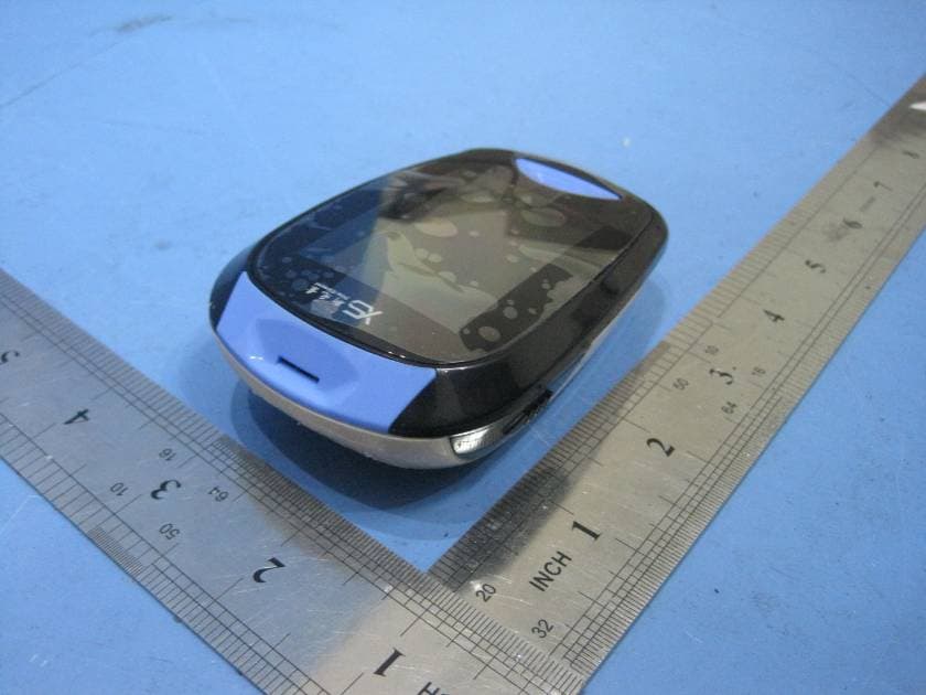
ZBSPFES-1TNB
Apr 17, 2011REMOTE & MOBILE BLOOD GLUCOSE MONITORING AND DIABETES PATIENT FOLLOW-UP SYSTEM
Equipment Class
DSS - Part 15 Spread Spectrum Transmitter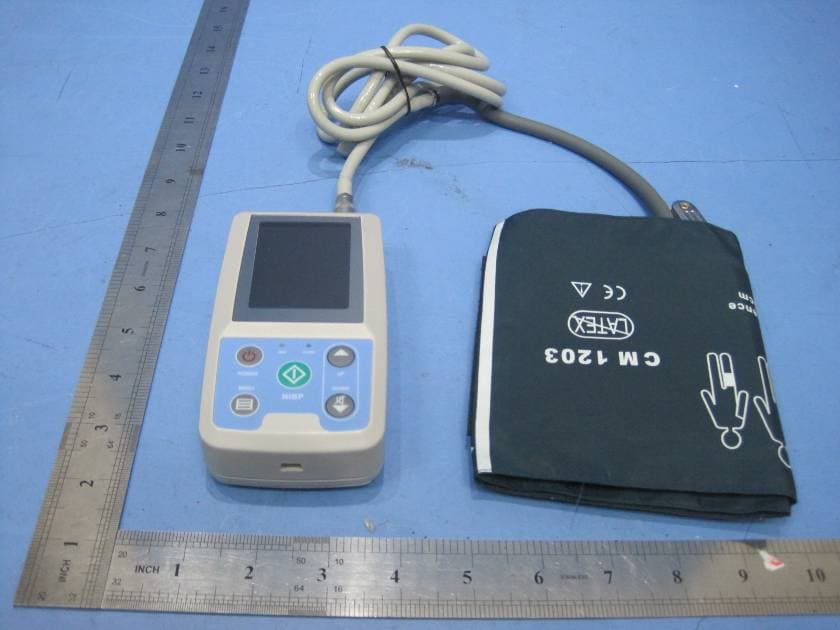
ZBSWRM-1XY
Mar 15, 2011REMOTE & MOBILE AMBULATORY BLOOD PRESSURE MONITORING SYSTEM
Equipment Class
DSS - Part 15 Spread Spectrum Transmitter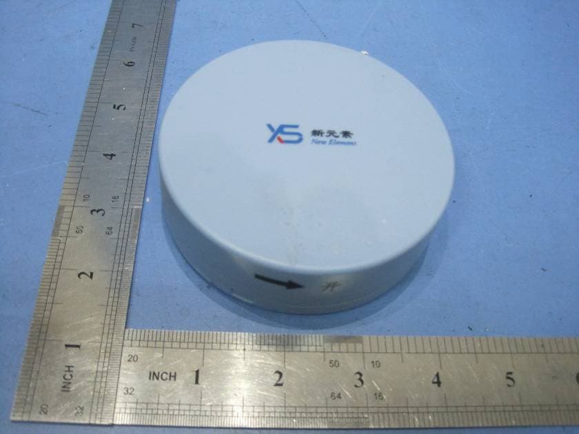
ZBSWRM-XPN
Mar 14, 2011REMOTE & MOBILE VOIDING DIARY MONITORING SYSTEM
Equipment Class
DSS - Part 15 Spread Spectrum Transmitter