ZLZ-WMTSTM70Telemetry Monitor
Shenzhen Mindray BIO-Medical electronics Co.,LTD.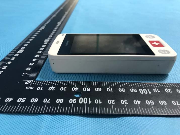
Click to zoom
Application Details
- Equipment Class
- DTS - Digital Transmission System
- Date of Grant
- Mar 22, 2020
- Application Purpose
- Original Equipment
- Date of Application
- Mar 16, 2020
- Equipment Note
- Telemetry Monitor
- Frequency Range
- 2402.00000000 - 2480.00000000
- Country
- China
Documents & Files
Document Text
Text extracted from the exhibit documents filed with the FCC. Open a document above to read the original.
Users Manual
T elemetry Monitor TM70 Mindray U ser Manual Shenzhen Mindray BIO-Medical electronics Co.,LTD. Mindray Building, Keji 12th Road South, Hi-tech Ind, Shenzhen, China Introduction TM80/TM70 Telemetry Monitor Operator's ManualI © Copyright 2019 Shenzhen Mindray Bio-Medical Electronics Co., Ltd. All rights reserved. ■Release time: 2019-10 ■Revision: 4.0 WA RN ING •Federal Law (USA) restricts this device to sale by or on the order of a phy- sician or other practitioner licensed by U.S. state law to use or order the use of this device. Intellectual Property StatementIntroduction IITM80/TM70 Telemetry Monitor Operator's Manual Intellectual Property Statement SHENZHEN MINDRAY BIO-MEDICAL ELECTRONICS CO., LTD. (hereinafter called Mindray) owns the intellectual property rights to this Mindray product and this manual. This man- ual may refer to information protected by copyrights or patents and does not convey any license under the patent rights of Mindray, nor the rights of others. Mindray intends to maintain the contents of this manual as confidential information. Disclosure of the information in this manual in any manner whatsoever without the writ- ten permission of Mindray is strictly forbidden. Release, amendment, reproduction, distribution, rental, adaption and translation of this manual in any manner whatsoever without the written permission of Mindray is strictly forbidden. , , and are the registered trademarks or trademarks owned by Mindray in China and other countries. All other trademarks that appear in this manual are used only for editorial purposes without the intention of improperly using them. They are the property of their respective owners. This posting serves as notice under 35 U.S.C.§287(a) for Mindray patents: http:// www.mindrayna.com/patents. Manufacturer’s Responsibility Contents of this manual are subject to changes without prior notice. All information contained in this manual is believed to be correct. Mindray shall not be liable for errors contained herein nor for incidental or consequential damages in connec- tion with the furnishing, performance, or use of this manual. Mindray is responsible for the effects on safety, reliability and performance of this prod- uct, only if: ■all installation operations, expansions, changes, modifications and repairs of this product are conducted by Mindray authorized personnel; ■the electrical installation of the relevant room complies with the applicable national and local requirements; ■the product is used in accordance with the instructions for use. IntroductionWarranty TM80/TM70 Telemetry Monitor Operator's ManualIII Warranty Mindray warrants that components within its products will be free from defects in work- manship and materials for a period of three years from the date of purchase except that disposable or one-time use products are warranted to be free from defects in workman- ship and materials up to a date one year from the date of purchase or the date of first use, whichever is sooner. This warranty does not cover consumable items such as, but not limited to, batteries, external cables, and sensors. Mindray shall not be liable for any incidental, special, or consequential loss, damage, or expense directly or indirectly arising from the use of its products. Liability under this warranty and the buyer’s exclusive remedy under this warranty is limited to servicing or replacing the affected products, at Mindray option, at the factory or at an authorized dis- tributor, for any product which shall under normal use and service appear to Mindray to have been defective in material or workmanship. Recommended preventative mainte- nance, as prescribed in the service manual, is the responsibility of the user and is not covered by this warranty. No agent, employee, or representative of Mindray has any authority to bind Mindray to any affirmation, representation, or warranty concerning its products, and any affirma- tion, representation or warranty made by any agent, employee, or representative shall not be enforceable by buyer or user. THIS WARRANTY IS EXPRESSLY IN LIEU OF, AND MINDRAY EXPRESSLY DISCLAIMS, ANY OTHER EXPRESS OR IMPLIED WARRANTIES, INCLUDING ANY IMPLIED WARRANTY OF MERCHANTABILITY, NON-INFRINGEMENT, OR FITNESS FOR A PARTICULAR PURPOSE, AND OF ANY OTHER OBLIGATION ON THE PART OF MINDRAY. Damage to any product or parts through misuse, neglect, accident, or by affixing any non-standard accessory attachments, or by any customer modification voids this war- ranty. Mindray makes no warranty whatsoever in regard to trade accessories, such being subject to the warranty of their respective manufacturers. A condition of this warranty is that the equipment or accessories which are claimed to be defective be returned when authorized, freight prepaid to Mindray DS USA, Inc., Mah- wah, New Jersey 07430 or its authorized representative. Mindray shall not have any responsibility in the event of loss or damage in transit. WARNING •Only skilled/trained clinical professionals should operate this equipment. •It is important for the hospital or organization that employs this equip- ment to carry out a reasonable service/maintenance plan. Neglect of this may result in machine breakdown or personal injury. Company ContactIntroduction IVTM80/TM70 Telemetry Monitor Operator's Manual Exemptions Mindray's obligation or liability under this warranty does not include any transportation or other charges or liability for direct, indirect or consequential damages or delay result- ing from the improper use or application of the product or the use of parts or accessories not approved by Mindray or repairs by people other than Mindray authorized personnel. This warranty does not extend to: ■Malfunction or damage caused by improper use or man-made failure. ■Malfunction or damage caused by unstable or out-of-range power input. ■Malfunction or damage caused by force majeure events, such as (i) flood, fire and earthquake or other similar elements of nature or …
Text truncated - open the document above for the full version.
Users Manual
ST MonitoringMonitoring ECG 7 - 18TM80/TM70 Telemetry Monitor Operator’s Manual 7.6.3ECG Waveform Area The ECG waveform area displays: 1.ECG Lead 2.ECG scale bar 3.ECG waveform 4.ECG filter setting 5.ECG scale 7.6.4About the ECG Waveform Area ■The ECG waveform, scale indicator, lead, and filter settings display in the configured ECG color. ■The ECG waveform area provides scrolling, real-time waveform data and an erase bar to provide a time indicator of oldest and new data. ■The ECG waveform area scrolls the waveform in the configured sweep speed. ■The ECG waveform area rails the top most value when the waveform exceeds the upper scale limit for real-time waveforms. ■The ECG waveform area rails the bottom most value when the waveform exceeds the lower scale limit for real-time waveforms. ■The ECG waveform area indicates a Pacer indicator when a pace pulse is detected and Paced is enabled. 7.7ST Monitoring ST segment analysis calculates ST segment elevations and depressions for individual leads and then displays them as numerics in the ST area. A positive value indicates ST segment elevation; a negative value indicates ST segment depression. ST monitoring is intended for adult and pediatric patients. 1 3 4 5 2 Monitoring ECGST Monitoring TM80/TM70 Telemetry Monitor Operator’s Manual7 - 19 7.7.1ST Safety Information 7.7.2 Switching ST Monitoring On and Off The ST monitoring function is disabled by default. Before you start ST monitoring, enable the ST function. 1.On the main screen, tap the HR digital area or ECG waveform area to enter the [ECG] menu. 2.In the [ECGParameter Setup] section, tap [ST]. 3.Switch on [ST Analysis]. Reliable ST monitoring can hardly be ensured if: ■You are unable to get a lead that is not noisy. ■Arrhythmias such as atrial fib/flutter cause irregular baseline. ■The patient is continuously ventricularly paced. ■The patient has left bundle branch block. In these cases, you may consider switching ST monitoring off. WA RN ING •ST values may be affected by such factors as some drugs or metabolic and conduction disturbances. •ST deviation is often calculated at a fixed offset from the J point. Changes in heart rate may affect ST. •The ST deviation measurement algorithm has been tested for accuracy. The significance of ST segment changes needs to be determined by a physician. •The TM80/TM70 provides ST deviation level change information. The clinical significance of the ST level change information should be deter- mined by a physician. ST MonitoringMonitoring ECG 7 - 20TM80/TM70 Telemetry Monitor Operator’s Manual 7.7.3Displaying ST Numerics When [ST Analysis] is switched on, ST digital area is displayed on the screen. The loca- tion of the ST digital area is dependent on the display configurations. For how to set the location of the ST digital area, refer to "Configuring the Display" on page 4 - 2. Numerics displayed in the ST digital area are different according to the lead type: ■When the 3-lead ECG leadwires are used, the ST digital area is not displayed. A ST value is displayed in the HR digital area. ■When the 5-lead ECG leadwires are used, seven ST values (ST-I, ST-II, ST-III, ST-aVR, ST-aVL, ST-aVF, ST-V) are displayed in the ST digital area. ■When the 6-lead ECG leadwires are used, eight ST values (ST-I, ST-II, ST-III, ST-aVR, ST-aVL, ST-aVF, ST-V a, ST-Vb) are displayed in the ST digital area. This example shows the ST digital area when the 6-lead ECG leadwires are used. Your screen may look slightly different: 7.7.4Setting ST Alarms 1.Tap the ST digital area to enter the [ST] menu. 2.Tap [ST Alarm Setup]. 3.In the [Setup] section, tap [ST Alarm Mode] and then select the desired mode: ◆[ Absolute]: you can separately set the alarm properties for each ST alarm. After selecting this option, the [ Auto Limits] option is displayed where you can initiate auto adjustment of alarm limits. ◆[Relative]: it is the default option. You can set the alarm properties for [ST Single] and [ST Dual] alarms. 1. Parameter label2. ST alarm activation state off icon 3. Lead label4. ST unit 5. ST numerics: a positive value indicates ST segment elevation, and a negative value indi- cates ST segment depression. 1 3 4 ) 2 5 Monitoring ECGQT/QTc Interval Monitoring TM80/TM70 Telemetry Monitor Operator’s Manual7 - 21 4.In the [Alarms] section, configure the options described in the following table. 7.8QT/QTc Interval Monitoring The QT interval is defined as the time between the beginning of the Q-wave and the end of the T-wave. It measures the total duration of ventricular depolarization (QRS duration) and repolarization (ST-T ). QT interval monitoring can assist in the detection of long QT syndrome. The QT interval has an inverse relationship to heart rate. Faster heart rates shorten the QT interval and slower heart rates prolong the QT interval. Therefore, several formulas can be used to correct the QT interval for heart rate. The heart rate corrected QT interval is abbreviated as QTc. Options DescriptionSettings* ST-I, ST-II, ST-III, ST-aVR, ST-aVF, ST-V, ST-Va, ST-Vb These options are displayed when [ST Alarm Mode] is set to [Absolute]. The lead label behind ST is con- sistent with the ECG cable type selected. On, Off Upper alarm limit range: 0.2 mV to 2.0 mV; the default is 0.2mV; the step is 0.01mV Lower alarm limit range: -2.0 mV to 0 mV; the default is -0.2mV; step is 0.01mV Alarm priority: Low, Med, High ST SingleThese options are displayed when [ST Alarm Mode] is set to [Relative]. On, Off Upper alarm limit range: 0 mV to 2.0 mV; the default is 0.1mV; the step is 0.01mV Lower alarm limit range: -2.0 mV to 0 mV; the default is -0.1mV; step is 0.01mV Alarm priority: Low, Med, High ST DualOn, Off Upper alarm limit range: 0 mV to 2.0 mV; the default is 0.1mV; the step is 0.01mV Lower alarm limit range: -2.0 mV to 0 mV; the default is -0.1mV; step is 0.01mV Alarm priority: Low, Med, High *The factory default settings are in bold. QT/QTc Interval MonitoringMonitoring ECG 7 - 22TM80/TM…
Text truncated - open the document above for the full version.
Cover Letter(s)
Shenzhen Mindray BIO-Medical electronics Co.,LTD. Date: Mar. 16, 2020 Federal Communications Commission Authorization and Evaluation Division Confidentiality Request regarding application for certification of FCC ID: ZLZ-WMTSTM70 Pursuant to Sections 0.457 and 0.459 of the Commission’s Rules, we hereby request confidential treatment of information accompanying this application as outlined below: Exhibit Type File Name Schematics Block Diagram Operational Description Schematics.pdf Block Diagram.pdf Operational Description.pdf The above materials contain trade secrets and proprietary information not customarily released to the public. The public disclosure of these materials may be harmful to the applicant and provide unjustified benefits to its competitors. The applicant understands that pursuant to Section 0.457 of the Rules, disclosure of this application and all accompanying documentation will not be made before the date of the Grant for this application. Sincerely, Shenzhen Mindray BIO-Medical electronics Co.,LTD. Signature Leo Shao / Manager Typed name and Title
Cover Letter(s)
Shenzhen Mindray BIO-Medical electronics Co.,LTD. FCC ID: ZLZ-WMTSTM70 POWER OF ATTORNEY Date: Mar. 16, 2020 Federal Communications Commission Authorization and Evaluation Division 7435 Oakland Mills Road Columbia, MD 21046 To Whom It May Concern: We, the undersigned, hereby authorize Waltek Services (ShenZhen) Co., Ltd. (Philo Zhong) on our behalf, to apply to the Federal Communications Commission on our equipment. Any and all acts carried out by Waltek Services (ShenZhen) Co., Ltd. (Philo Zhong) on our behalf shall have the same effect as acts of our own. This authorization expires on Mar. 15, 2021. This is to advise that we are in full compliance with the Anti-Drug Abuse Act. We, Shenzhen Mindray BIO-Medical electronics Co.,LTD. are not subject to a denial of federal benefits pursuant to Section 5301 of the Anti-Drug Act of 1988, 21 USC853a, and no party to the application is subject to a denial of federal benefits pursuant to that section. Sincerely, Shenzhen Mindray BIO-Medical electronics Co.,LTD. Signature Leo Shao / Manager Typed name and Title
External Photos
Appendix-TM70-Photos Page 3 of 21 EUT – External View Model TM70 FCC ID: ZLZ-WMTSTM70 Appendix-TM70-Photos Page 4 of 21 Appendix-TM70-Photos Page 5 of 21 Appendix-TM70-Photos Page 6 of 21
ID Label/Location Info
TM70 Label Sample and Location
Internal Photos
Appendix-TM70-Photos Page 7 of 21 EUT – Internal View Model TM70 FCC ID: ZLZ-WMTSTM70 608MHz WMTS AN T. 1.4GHz WMTS ANT. BLE WMTS AN T. Appendix-TM70-Photos Page 8 of 21 Appendix-TM70-Photos Page 9 of 21 Appendix-TM70-Photos Page 10 of 21 Appendix-TM70-Photos Page 11 of 21
Internal Photos
Appendix-TM70-Photos Page 12 of 21 Appendix-TM70-Photos Page 13 of 21 Appendix-TM70-Photos Page 14 of 21 Appendix-TM70-Photos Page 15 of 21 Appendix-TM70-Photos Page 16 of 21
Internal Photos
Appendix-TM70-Photos Page 17 of 21 Appendix-TM70-Photos Page 18 of 21 Appendix-TM70-Photos Page 19 of 21 Appendix-TM70-Photos Page 20 of 21 Appendix-TM70-Photos Page 21 of 21 ======End======
RF Exposure Info
Reference No.: WTS19S09066147W003 Page 1 of 4 Waltek Services (Shenzhen) Co.,Ltd. http://www.waltek.com.cn 1 Test Summary Test Items Test Requirement Result Maximum Permissible Exposure (Exposure of Humans to RF Fields) 1.1307(b)(1) PASS Reference No.: WTS19S09066147W003 Page 2 of 4 2 RF Exposure Test Requirement: FCC Part 1.1307 Test Mode: The EUT work in test mode(Tx). 2.1 Requirements Systems operating under the provisions of this section shall be operated in a manner that ensures that the public is not exposed to radio frequency energy levels in excess limit for maximum permissible exposure. In accordance with 47 CFR FCC Part 2 Subpart J, section 2.1091 this device has been defined as a mobile device whereby a distance of 0.2 m normally can be maintained between the user and the device. 2.2 The procedures / limit FCC Part 1.1307: (A) Limits for Occupational / Controlled Exposure Frequency Range (MHz) Electric Field Strength (E) (V/m) Magnetic Field Strength (H) (A/m) Power Density (S) (mW/ cm 2 ) Averaging Time |E| 2 ,|H| 2 or S (minutes) 0.3-3.0 614 1.63 (100)* 6 3.0-30 1842 / f 4.89 / f (900 / f)* 6 30-300 61.4 0.163 1.0 6 300-1500 F/300 6 1500-100,000 5 6 (B) Limits for General Population / Uncontrolled Exposure Frequency Range (MHz) Electric Field Strength (E) (V/m) Magnetic Field Strength (H) (A/m) Power Density (S) (mW/ cm 2 ) Averaging Time |E| 2 ,|H| 2 or S (minutes) 0.3-1.34 614 1.63 (100)* 30 1.34-30 824/f 2.19/f (180/f)* 30 30-300 27.5 0.073 0.2 30 300-1500 F/1500 30 1500-100,000 1.0 30 Note: f = frequency in MHz ; *Plane-wave equivalent power density Reference No.: WTS19S09066147W003 Page 3 of 4 2.3 MPE Calculation Method Predication of MPE limit at a given distance S = power density (in appropriate units, e.g. mW/cm 2 ) P = power input to the antenna (in appropriate units, e.g., mW). G = power gain of the antenna in the direction of interest relative to an isotropic radiator, the power gain factor, is normally numeric gain. R = distance to the center of radiation of the antenna (appropriate units, e.g., cm) From the peak EUT RF output power, the minimum mobile separation distance, d=5mm, as well as the gain of the used antenna, the RF power density can be obtained BLE Conducted Peak power(dBm) Conducted Peak power(mW) Source-based time- averaged maximum conducted output power(mW) Minimum test separation distance required for the exposure conditions (mm) SAR Test Exclusion Thresholds(mW) 6.37 4.36 4.36 5 10 611.06MHz Conducted Peak power(dBm) Conducted Peak power(mW) Source-based time- averaged maximum conducted output power(mW) Minimum test separation distance required for the exposure conditions (mm) SAR Test Exclusion Thresholds(mW) 0.4 1.096 1.096 5 10 Note: the following is Source-based time-averaged maximum output power Calculation Frequency Source-based time-averaged maximum output power Substituted (0dBm) Source-based time- averaged maximum output power (MHz) (dBμV/m) (dBμV/m) (dBm) 611.06 95.60 95.2 0.4 Reference No.: WTS19S09066147W003 Page 4 of 4 3 Photographs of test setup and EUT. Note: Please refer to appendix TM70-Photo. ======End of Report======
Test Report
Waltek Services (Shenzhen) Co.,Ltd. http://www.waltek.com.cn Page 1 of 37 TEST REPORT Referen ce No. .................... : WTS19S09066147W002 V1 FCC ID ................................ : ZLZ-WMTSTM70 Applicant ............................ : Shenzhen Mindray BIO-Medical electronics Co.,LTD. Address .............................. : Mindray Building, Keji 12th Road South, Hi-tech Ind, Shenzhen , C hina Manufacturer .................... : The same as above Address .............................. : The same as above Product ............................... : Telemetry Monitor Model(s). ............................ : TM70 Brand Nam e ....................... : Mindray Standards........................... : FCC CFR47 Part 15.247: 2017 Date of Receipt sample .... : 2019-09-23 Date of Test ....................... : 2019-09-24 to 2019-11-25 Date of Issue ...................... : 2020-03-17 Test Result ......................... : Pass Remarks: The re sults shown in this test report refer only to the sample(s) tested, this test report cannot be reproduced, except in full, without prior written permission of the company. The report would be invalid without specific stamp of test institute and the signatures of compiler and approver. Prepared By: Waltek Services (Shenzhen) Co., Ltd. Address: 1/F., Fukangtai Building, West Baima Road, Songgang Street, Baoan District, Shenzhen, Guangdong, China Tel :+86-755-83551033 Fax:+86-755-83552400 Compiled by: Approved by: Ford Wang / Project Engineer Philo Zhong / Manager Reference No.: WTS19S09066147W002 V1 Page 2 of 37 Waltek Services (Shenzhen) Co.,Ltd. http://www.waltek.com.cn 2 Contents Page 1 COVER PAGE ........................................................................................................................................... 1 2 CONTENTS ............................................................................................................................................................ 2 3 REVISION HISTORY ............................................................................................................................................ 3 4 GENERAL INFORMATION .................................................................................................................................. 4 4.1 GENERAL DESCRIPTION OF E.U.T. ................................................................................................................ 4 4.2 DETAILS OF E.U.T. ......................................................................................................................................... 4 4.3 CHANNEL LIST ................................................................................................................................................. 5 5 TEST FACILITY ..................................................................................................................................................... 6 5.1 TEST MODE ..................................................................................................................................................... 7 6 TEST SUMMARY .................................................................................................................................................. 8 7 EQUIPMENT USED DURING TEST .................................................................................................................. 9 7.1 EQUIPMENTS LIST ........................................................................................................................................... 9 7.2 DESCRIPTION OF SUPPORT UNITS ............................................................................................................... 10 7.3 MEASUREMENT UNCERTAINTY ..................................................................................................................... 10 7.4 TEST EQUIPMENT CALIBRATION ................................................................................................................... 10 8 RADIATED EMISSIONS..................................................................................................................................... 11 8.1 EUT OPERATION ........................................................................................................................................... 11 8.2 TEST SETUP .................................................................................................................................................. 12 8.3 SPECTRUM ANALYZER SETUP ...................................................................................................................... 13 8.4 TEST PROCEDURE ........................................................................................................................................ 14 8.5 CORRECTED AMPLITUDE & MARGIN CALCULATION ..................................................................................... 14 8.6 SUMMARY OF TEST RESULTS ....................................................................................................................... 15 9 CONDUCTED SPURIOUS EMISSIONS .......................................................................................................... 18 9.1 TEST PROCEDURE ........................................................................................................................................ 18 9.2 TEST RESULT ................................................................................................................................................ 19 10 BAND EDGE MEASUREMENT ........................................................................................................................ 23 10.1 TEST PRODUCE ........................................................................................................................................ 23 10.2 TEST RESULT .....................................................................................................................…
Text truncated - open the document above for the full version.
Test Setup Photos
Appendix-TM70-Photos Page 1 of 21 Photographs –Constructional Details BLE and WMTS Setup photo Model TM70 FCC ID: ZLZ-WMTSTM70 Photograph - Spurious Emissions Radiated Test Setup Below 30MHz Test Site 2# Photograph - Spurious Emissions Radiated Test Setup For 30MHz-1000MHz Appendix-TM70-Photos Page 2 of 21 For Above 1GHz
Contact Information
Applicant
leo Shao
Test Firm
WALTEK TESTING GROUP CO., LTD.Joy Zhou
[email protected]0769-22676998
Technical Specifications
| # | Rule Parts | Frequency Range | Power Output |
|---|---|---|---|
| 1 | 15C | 2.40 GHz - 2.48 GHz | 4.00 mW |
Other Applications from Shenzhen Mindray BIO-Medical electronics Co.,LTD.
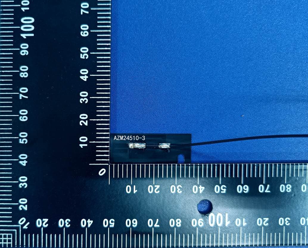
ZLZ-ALXC29
Aug 29, 2024Wireless Flat Panel Wireless Module
Equipment Class
DTS - Digital Transmission System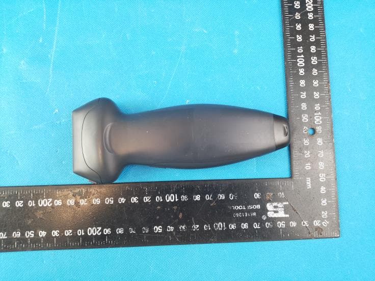
ZLZ-TEARQ
Aug 20, 2024Diagnostic Ultrasound System
Equipment Class
JAB - Part 15 Class B Digital Device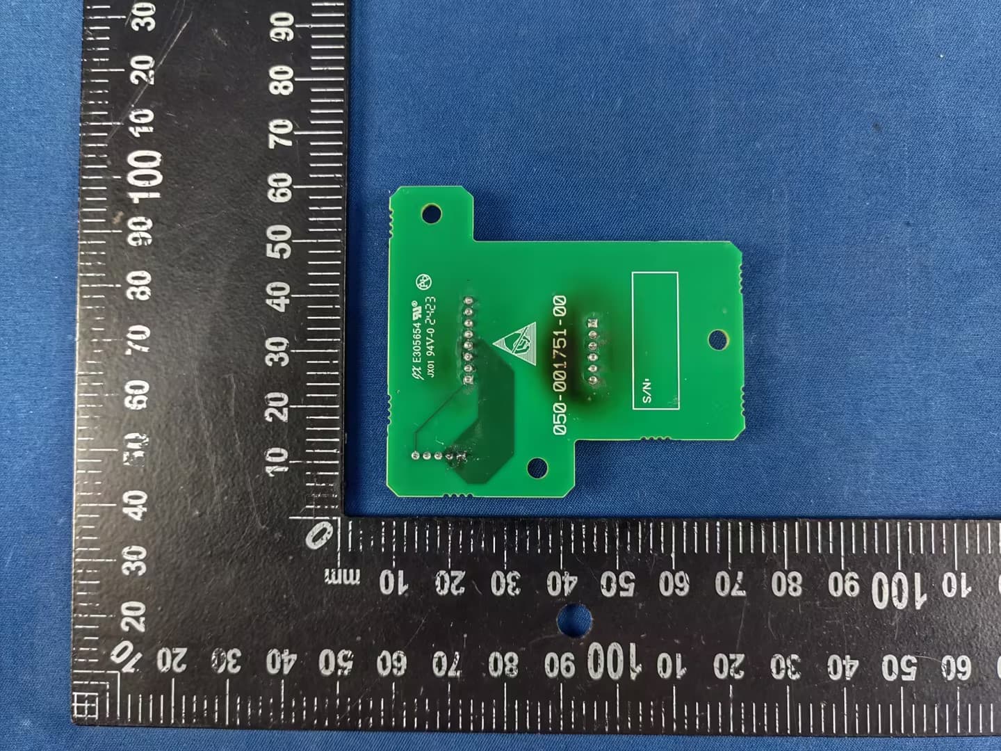
ZLZ-ZLG600A-T2
Jul 03, 2024Card Reader Module
Equipment Class
DXX - Part 15 Low Power Communication Device Transmitter
ZLZ-WLINK
May 18, 2021wireless module
Equipment Class
NII - Unlicensed National Information Infrastructure TX
ZLZ-PANLINK3
Jun 16, 2020Bluetooth module
Equipment Class
DTS - Digital Transmission System