ZLZTDBTSEBluetooth Low Energy Module
Shenzhen Mindray BIO-Medical electronics Co.,LTD.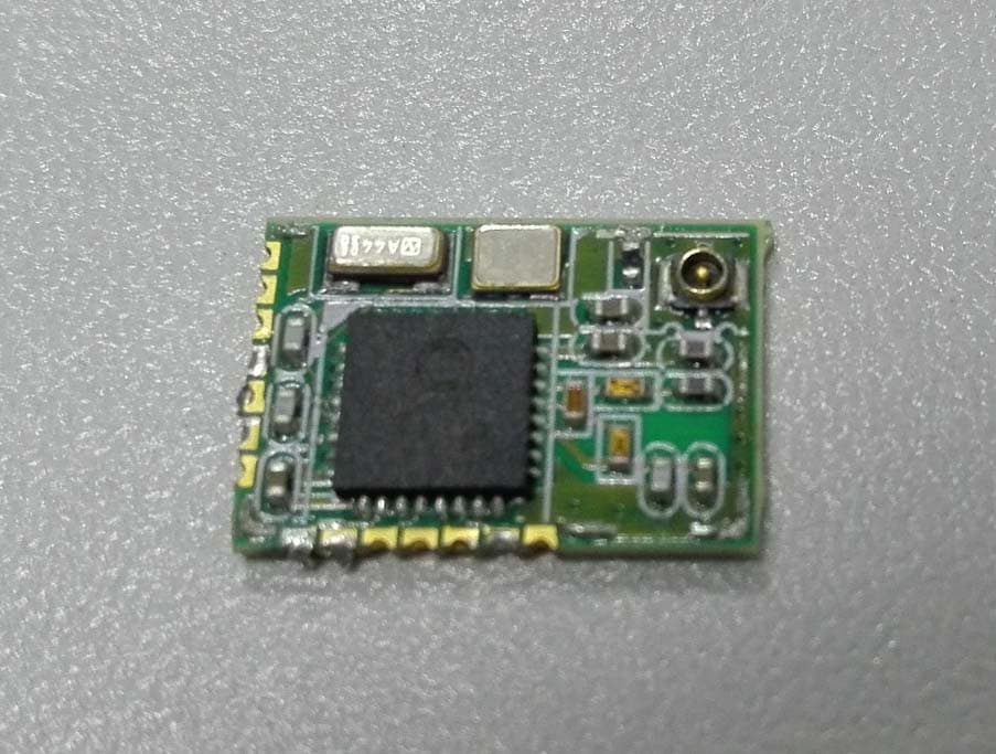
Click to zoom
Application Details
- Equipment Class
- DTS - Digital Transmission System
- Date of Grant
- Aug 24, 2015
- Application Purpose
- Original Equipment
- Date of Application
- Aug 24, 2015
- Equipment Note
- Bluetooth Low Energy Module
- Frequency Range
- 2402.00000000 - 2480.00000000
- Country
- China
Documents & Files
Document Text
Text extracted from the exhibit documents filed with the FCC. Open a document above to read the original.
Users Manual
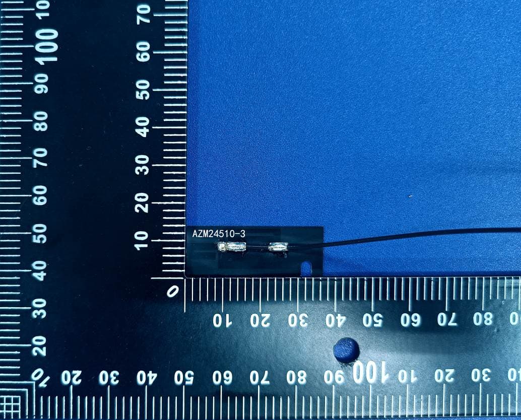
1.1 General Decription Panlink II module consists of a BT module, crystal and antenna connector. This module can change UART signal to wireless signal using Bluetooth low energy technology. This module uses external antenna via a Antenna connector. Panlink II communication type is piconet, which means Panlink II transfers data to another Panklink(one is master, the other one is salve). When transfering data from master to slave, data was given to master by UART. Then master Panlink II controls signal, frames, radiation power and transmits them via the antenna to slave Panlink II. Slave Panlink II get RF signal via the antenna and resolve it to data. When transfering data from slave to master, data was given to master by UART. Then slave Panlink II controls signal, frames, radiation power and transmits them via the antenna to master Panlink II. Master Panlink II get RF signal via the antenna and resolve it to data. And there are some requisition for end-user as below, 圃 The module is limited to OEM installation ONLY; 圃 The OEM integrators is responsible for ensuring that end-user has no manual instructions to remove or install module; 圃 The module is limited to installation in mobile or fixed application 圃 The separate approval is required for all other operating configurations, including portable configuration with respect to Part 2.1093 and different antenna configurations; 圃 The host manufacturer is responsible for ensuring that after the module is installed and operational the host continues to be compliant with the Part 15B unintentional radiator requirements 1.2 Block diagram 1.3 Interface and pin definition No. Pin name Type description 1 to 8 NC / No use 9 DC I Debug clock 10 DD O Debug data 11 SLEEP_OUT/P3_0 O Wakeup out 12 VDD Power Power in 13 GND Power ground 14 Reset RSTN Reset in 15 Wake/P0_3 I Wake up input 16 UART_RXD0 I Uart in, baud rate is 115200 17 UART_TXD0 O Uart out, baud rate is 115200 18 nCS1/CTSn1/P1_2 I/O Reserved 19 CLK1/RTSn1/P1_3 I/O Reserved 20 MOSI1/TXD1/P1_1 I/O Reserved 21 MISO1/RXD1/P1_0 I/O Reserved 22 CD O Module detect pin 23 RF Connector RF Connect to external antenna 1.4 Operation specification ABSOLUTE MAXIMUM RATINGS Over operating room temperature range (unless otherwise noted) Item VA L U E UNIT Supply voltage range -0.3 to 3.9 V Voltage range to any of digital pins -0.3 to VDD + 0.3, <3.9 V Storage temperature range -40 to +85 °C RECOMMENDED OPERATING CONDITIONS Over operating room temperature range (unless otherwise noted) Item MIN NOM MAX UNIT Supply voltage range 2.4 3.6 V Operational temperature range -20 +70 °C 1.5 Wireless specifications Protocol:Bluetooth low energy 4.0 Modulation mode:GFSK Operating frequency:2402 ~ 2480MHz(40 channels) Channel spacing:2MHz Wireless baud rate(data rate): 1Mbps Output power (transfer power): ≤2.5mW Data security : 128bit AES 1.6 Mechanical and package description Dimension is 9.6mm*13.9mm*2.3mm, and package type is SMT. This device and its antenna must not be located or operating in conjunction with any other antenna and transmitter. This device complies with part 15 of the FCC rules. Operation is subject to the following two conditions: (1) this device may not cause harmful interference, and (2) this device must accept any interference received, including interference that may cause undesired operation. Changes or modifications not expressly approved by the party responsible for compliance could void the user’s authority to operate the equipment. NOTE: This equipment has been tested and found to comply with the limits for a Class B digital device, pursuant to part 15 of the FCC Rules. These limits are designed to provide reasonable protection against harmful interference in a residential installation. This equipment generates uses and can radiate radio frequency energy and, if not installed and used in accordance with the instructions, may cause harmful interference to radio communications. However, there is no guarantee that interference will not occur in a particular installation. If this equipment does cause harmful interference to radio or television reception, which can be determined by turning the equipment off and on, the user is encouraged to try to correct the interference by one or more of the following measures: ‐ Reorient or relocate the receiving antenna. ‐ Increase the separation between the equipment and receiver. ‐Connect the equipment into an outlet on a circuit different from that to which the receiver is connected. ‐Consult the dealer or an experienced radio/TV technician for help important announcement LABEL OF THE END PRODUCT: The final end product must be labeled in a visible area with the following" Contains FCC ID: ZLZTDBTSE " and Contains IC: 9726A‐TDBTSE. The FCC part 15.19 statement below has to also be available on the label: This device complies with Part 15 of FCC rules. Operation is subject to the following two conditions: (1) this device may not cause harmful interference and (2) this device must accept any interference received, including interference that may cause undesired operation. A user manual with the end product must clearly indicate the operating requirements and conditions that must be observed to ensure compliance with current FCC RF exposure guidelines. The end product with an embedded Panlink II Module may also need to pass the FCC Part 15 unintentional emission testing requirements and be properly authorized per FCC Part 15. To comply with FCC regulations limiting both maximum RF output power and human exposure to RF radiation, the maximum antenna gain including cable loss in general exposure condition must not exceed 3.5dBi. The modular used RP‐SMA antenna connector and tested 3 antennas, Antenna Antenna Type Maximum Antenna Gain Antenna 1 FPC 2dBi Antenna 2 Dipole 3.5dBi Antenna 3 FPC 1dBi If end users use others antennas except stated, end‐users need test radiated emission, RF exposure refer to FCC C2PC rules. ‐ English: This device complies with Indust…
Text truncated - open the document above for the full version.
Cover Letter(s)
CONFIDENTIALITY REQUEST for Certification Service in USA Federal Communication Commission Equipment Authorization Division, Application Processing Branch 7435 Oakland Mills Road Columbia, MD 21048 2015-7-31 TO WHOM IT MAY CONCERN Pursuant to Paragraphs §0.457 and 0.459 of the Commission’s Rules (47 C.F.R.) and Section §552(b)(4) of the Freedom of Information Act, we requests confidentiality for the following products: FCC ID Model name ZLZTDBTSE Panlink2 For the product stated above, we request permanent confidentiality for exhibits which contain Operational Description, Block Diagram, Schematics, The above exhibits contain our trade secrets and proprietary information that could be of benefit to our competitors. If you have any questions, please feel free to contact me at the address shown below. Sincerely, (signed) Name: Company: Shenzhen Mindray Bio-Medical Electronics Co.,Ltd. Address: Mindray Buiding,Keji 12th Road South,High-tech Industrial Park,Nanshan,Shenzhen,P.R.China Phone:86-755-81885333 Fax: +86-755-26582680 Email: liuyan-d @mindray.com
Cover Letter(s)
Shenzhen Mindray Bio-Medical Electronics Co.,Ltd FCC Modular Approval Statement 1 Receiver Federal Communication Commission Equipment Authorization Devision, Application Processing Branch 7435 Oakland Mills Road Columbia, MD 21048 Subject: signal Modular Approval Statement Date:2015-7-31 FCC Certification Number: ZLZTDBTSE Model Name/Number: Panlink2 TO WHOM IT MAY CONCERN Pursuant to Paragraphs CFR § 15.212, we herewith declare for our module. Modular approval requirement Yes No * (a) The radio elements must have the radio frequency circuitry be shielded. Physical/discrete and tuning capacitors may be located external to the shield, but must be on the module assembly. Y *Please provide a detailed explanation if the answer is “No.”: (b) The module shall have buffered modulation/data input(s) (if such inputs are provided) to ensure that the module will comply with the requirements set out in the applicable standard under conditions of excessive data rates or over- modulation. Y *Please provide a detailed explanation if the answer is “No.”: (c) The module shall have its own power supply regulation on the module. This is to ensure that the module will comply with the requirements set out in the applicable standard regardless of the design of the power supplying circuitry in the host device which houses the module. Y *Please provide a detailed explanation if the answer is “No.”: (d) The module shall comply with the provisions for external power amplifiers and antennas detailed in this standard. The equipment certification submission shall contain a detailed description of the configuration of all antennas that will be used with the module. Y *Please provide a detailed explanation if the answer is “No.”: (e) The module shall be tested for compliance with the applicable standard in a stand-alone configuration, i.e. the module must not be inside another device during testing. Y *Please provide a detailed explanation if the answer is “No.”: (f) The module shall comply with the Category I equipment labeling requirements and CFR § 15.212(a)(1)(vi). Y *Please provide a detailed explanation if the answer is “No.”: Shenzhen Mindray Bio-Medical Electronics Co.,Ltd FCC Modular Approval Statement 2 (g) The module shall comply with applicable RSS-102 exposure requirements and any applicable FCC RF exposure requirement which are based on the intended use/configurations. Y *Please provide a detailed explanation if the answer is “No.”: (i) The modular transmitter complies with all applicable FCC rules. Instructions for maintaining compliance are given in the user instructions. Y If you have any questions, please feel free to contact us at the address shown below Best Regards, ______________________ Name of person authorized to sign Company name Shenzhen Mindray Bio-Medical Electronics Co.,Ltd. Address Mindray Buiding,Keji 12th Road South,High-tech Industrial Park,Nanshan,Shenzhen,P.R.China Phone No. 86-755-81885333
External Photos
External Photo
ID Label/Location Info
Unit:mm IC: 9726A‐TDBTSE M/N: Panlink2 FCC ID: ZLZTDBTSE
Internal Photos
External Photo
RF Exposure Info
FCC RF Exposure FCC ID: ZLZTDBTSE Applicant: Shenzhen Mindray Bio-Medical Electronics Co.,Ltd. Exposure category: General population/uncontrolled environment EUT Type: Production Unit Device Type: Portable Device Refer Standard: KDB 447498 D01 General RF Exposure Guidance v05r02 FCC Part 2 §2.1093 Evaluation method According to KDB447498 D01 General RF Exposure Guidance v05r01Section 4.3.1 Standalone SAR test exclusion considerations:“ Unless specifically required by the published RF exposure KDB procedures, standalone 1-g head or body and 10-g extremity SAR evaluation for general population exposure conditions, by measurement or numerical simulation, is not required when the corresponding SAR Test Exclusion Threshold condition, listed below, is satisfied. These test exclusion conditions are based on source-based time-averaged maximum conducted output power of the RF channel requiring evaluation, adjusted for tune-up tolerance, and the minimum test separation distance required for the exposure conditions.22 The minimum test separation distance is determined by the smallest distance from the antenna and radiating structures or outer surface of the device, according to the host form factor, exposure conditions and platform requirements, to any part of the body or extremity of a user or bystander (see 5) of section 4.1). To qualify for SAR test exclusion, the test separation distances applied must be fully explained and justified by the operating configurations and exposure conditions of the transmitter and applicable host platform requirements, typically in the SAR measurement or SAR analysis report, according to the required published RF exposure KDB procedures. When no other RF exposure testing or reporting is required, a statement of justification and compliance must be included in the equipment approval, in lieu of the SAR report, to qualify for the SAR test exclusion. When required, the device specific conditions described in the other published RF exposure KDB procedures must be satisfied before applying these SAR test exclusion provisions; for example, handheld PTT two-way radios, handsets, laptops & tablets etc.23 “[(max. power of channel, including tune-up tolerance, mW)/ (min. test separation distance, mm)] · [√f (GHz)]≤ 3.0 for 1-g SAR and ≤ 7.5 for 10-g extremity SAR, where: • f (GHz) is the RF channel transmit frequency in GHz • Power and distance are rounded to the nearest mW and mm before calculation • The result is rounded to one decimal place for comparison • 3.0 and 7.5 are referred to as the numeric thresholds in the step 2 below The test exclusions are applicable only when the minimum test separation distance is ≤ 50 mm and for transmission frequencies between 100 MHz and 6 GHz. When the minimum test separation distance is <5 mm, a distance of 5 mm according to 5) in section 4.1 is applied to determine SAR test exclusion. Conducted Power Results Bluetooth BLE 4.0 Channel Channel 0 Channel 20 Channel 39 Output Power (dBm) 1.96 1.24 1.35 Manufacturing tolerance Bluetooth BLE 4.0 Channel Channel 0 Channel 20 Channel 39 Target (dBm) 1.0 1.0 1.0 Tolerance ±(dB) 1.0 1.0 1.0 Evaluation Results Bluetooth BLE 4.0 Frequency Antenna Distance (mm) RF output power (including tune-up tolerance) SAR Test Exclusion Threshold SAR Test Exclusion dBm mW 2402MHz 5 2 1.59 0.5<3.0 Yes 2442MHz 5 2 1.59 0.5<3.0 Yes 2480MHz 5 2 1.59 0.5<3.0 Yes Conclusion The measurement results comply with the FCC Limit per 47 CFR 2.1093 for the uncontrolled RF Exposure and SAR Exclusion Threshold per KDB 447498 v05r02.
Test Report
Report No.: SET2015-08708 CCIC-SET/T(00) Page 1 of 50 RF TEST REPORT Report No.: SET2015-08708 Product Name: Bluetooth Low Energy Module FCC ID: ZLZTDBTSE IC: 9726A-TDBTSE Model No. : Panlink2 Applicant: Shenzhen Mindray Bio-Medical Electronics Co.,Ltd. Address: Mindray Buiding,Keji 12th Road South,High-tech Industrial Park,Nanshan,Shenzhen,P.R.China Dates of Testing: 06/15/2015 — 06/19/2015 Issued by: CCIC-SET Lab Location: Electronic Testing Building, Shahe Road, Xili, Nanshan District, Shenzhen, 518055, P. R. China Tel: 86 755 26627338 Fax: 86 755 26627238 This test report consists of 50 pages in total. It may be duplicated completely for legal use with the approval of the applicant. It should not be reproduced except in full, without the written approval of our laboratory. The client should not use it to claim product endorsement by CCIC-SET. The test results in the report only apply to the tested sample. The test report shall be invalid without all the signatures of testing engineers, reviewer and approver. Any objections must be raised to CCIC-SET within 20 days since the date when the report is received. It will not be taken into consideration beyond this limit. Report No.: SET2015-08708 CCIC-SET/T(00) Page 2 of 50 Test Report Product Name ...................... : Bluetooth Low Energy Module Brand Name ......................... : Mindray Trade Name .......................... : Applicant .............................. : Shenzhen Mindray Bio-Medical Electronics Co.,Ltd. Applicant Address ............... : Mindray Buiding,Keji 12th Road South,High-tech Industrial Park,Nanshan,Shenzhen,P.R.China Manufacturer ........................ : Shenzhen Mindray Bio-Medical Electronics Co.,Ltd. Manufacturer Address ........ : Mindray Buiding,Keji 12th Road South,High-tech Industrial Park,Nanshan,Shenzhen,P.R.China Test Standards ..................... : 47 CFR Part 15 Subpart C:Radio Frequency Devices RSS-247 Issue 1, May 2015 Digital Transmission Systems (DTSs), Frequency Hopping Systems (FHSs) and Licence-Exempt Local Area Network (LE-LAN) Devices Test Result ........................... : PASS Tested by ............................ : 2015.06.19 Lu Lei, Test Engineer Reviewed by ......................... : 2015.06.19 Zhu Qi, Senior Egineer Approved by ........................ : 2015.06.19 Wu Li’an,Manager Report No.: SET2015-08708 CCIC-SET/T(00) Page 3 of 50 TABLE OF CONTENTS 1. GENERAL INFORMATION .................................................................................................... 4 1.1. EUT Description ....................................................................................................................... 4 1.2. Test Standards and Results ........................................................................................................ 6 1.3. Description of test environment test modes .............................................................................. 7 1.4. Test Facilities ............................................................................................................................ 8 2. 47 CFR PART 15C REQUIREMENTS .................................................................................... 9 2.1. Antenna requirement ................................................................................................................. 9 2.2. Peak Output Power.................................................................................................................. 10 2.3. Bandwidth ............................................................................................................................... 12 2.3.7. Conducted Band Edges and Spurious Emissions .................................................................... 16 2.4. Power spectral density (PSD) ................................................................................................. 21 2.5. Conducted Emission ............................................................................................................... 24 2.6. Radiated Band Edge and Spurious Emission .......................................................................... 28 3. LIST OF MEASURING EQUIPMENT ................................................................................. 50 Change History Issue Date Reason for change 1.0 2015.06.19 First edition Report No.: SET2015-08708 Page 4 of 50 1. General Information 1.1. EUT Description EUT Type Bluetooth Low Energy Module Hardware Version 01-01-/ Software Version 1.0 Power Supply 3.0V DC Temperature operating range -20~70°C EUT supports Radios application Bluetooth V4.0 BLE Frequency Range 2402MHz~2480MHz Channel Number 40 Bit Rate of Transmitter 1Mbps Modulation Type GFSK Antenna Type Antenna 1: FPC Antenna Antenna 2: Dipole Antenna Antenna 3: FPC Antenna Antenna Gain Antenna 1: 2dBi Antenna 2: 3.5dBi Antenna 3: 1dBi Note 1: The EUT is a Bluetooth Low Energy Module, it contain Bluetooth 4.0 LTE Module operating at 2.4GHz ISM band; the frequencies allocated for the Bluetooth 4.0 LTE is F(MHz)=2402+2*n (0<=n<=39). The lowest, middle, highest channel numbers of the Bluetooth Module used and tested in this report are separately 0 (2402MHz), 20(2442MHz) and 39 (2480MHz). Note 2: For a more detailed description, please refer to Specification or User’s Manual supplied by the applicant and/or manufacturer. Report No.: SET2015-08708 Page 5 of 50 Antenna 1 Antenna 2 Antenna 3 Report No.: SET2015-08708 Page 6 of 50 1.2. Test Standards and Results The objective of the report is to perform testing according to 47 CFR Part 15 Subpart C (Bluetooth, 2.4GHz ISM band radiators) for the EUT FCC Certification: No. Identity Document Title 1 47 CFR Part 15 Subpart C 2013 Radio Frequency Devices 2 ANSI C63.10 2013 American National Standard for Testing Unlicensed Wireless Devices 3 RSS-GEN: Issue 4,November 2014: General Requirements and Information for the Certification of Radio Apparatus 4 RSS-247:Issue 1,December2015: Digital Transmission …
Text truncated - open the document above for the full version.
Test Setup Photos
Setup Photo
Contact Information
Applicant
leo Shao
Test Firm
CCIC-SETQi Zhu
Technical Specifications
| # | Rule Parts | Frequency Range | Power Output |
|---|---|---|---|
| 1 | 15C | 2.40 GHz - 2.48 GHz | 1.57 mW |
Other Applications from Shenzhen Mindray BIO-Medical electronics Co.,LTD.
ZLZ-ALXC29
Aug 29, 2024Wireless Flat Panel Wireless Module
Equipment Class
DTS - Digital Transmission System
ZLZ-TEARQ
Aug 20, 2024Diagnostic Ultrasound System
Equipment Class
JAB - Part 15 Class B Digital Device
ZLZ-ZLG600A-T2
Jul 03, 2024Card Reader Module
Equipment Class
DXX - Part 15 Low Power Communication Device Transmitter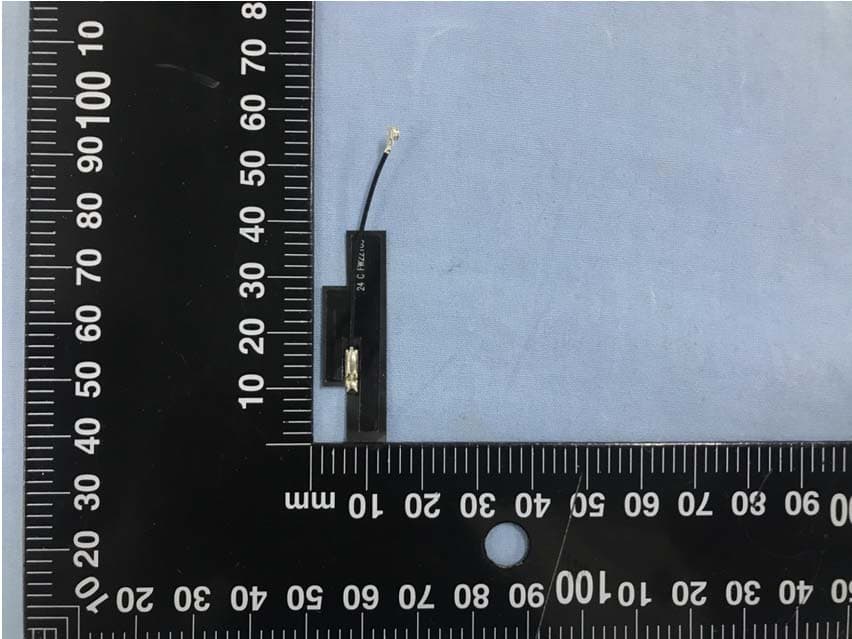
ZLZ-WLINK
May 18, 2021wireless module
Equipment Class
NII - Unlicensed National Information Infrastructure TX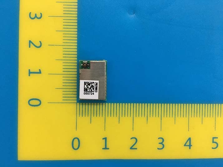
ZLZ-PANLINK3
Jun 16, 2020Bluetooth module
Equipment Class
DTS - Digital Transmission System