ZPNVS62U005TPMS Sensor
CUB ELECPARTS INC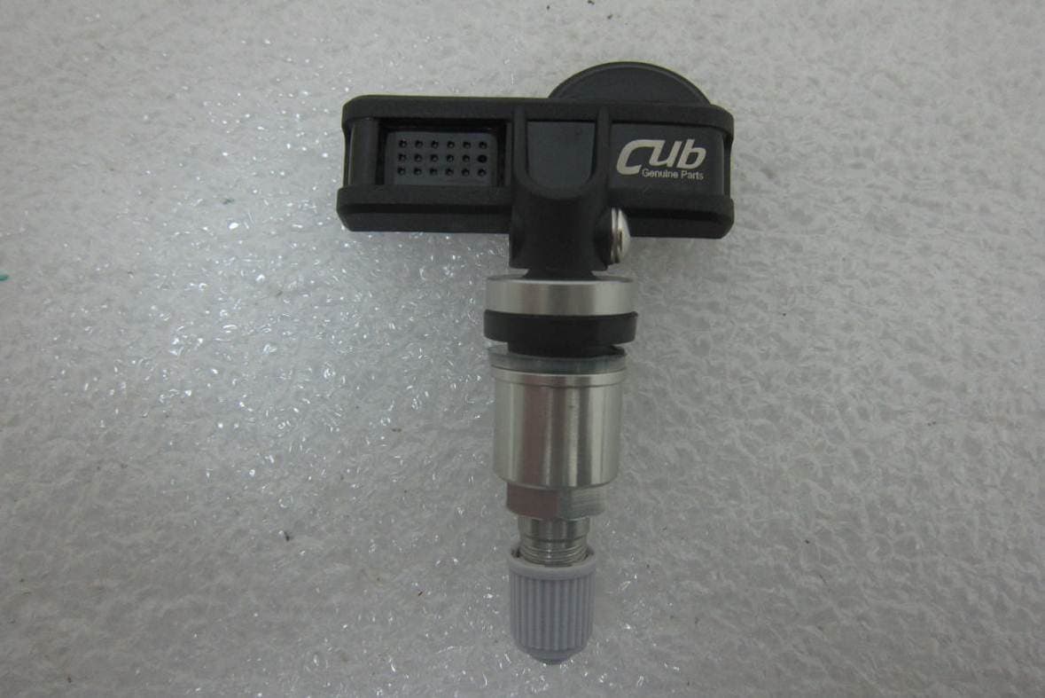
Click to zoom
Application Details
- Equipment Class
- DSC - Part 15 Security/Remote Control Transmitter
- Date of Grant
- Oct 30, 2014
- Application Purpose
- Original Equipment
- Date of Application
- Oct 29, 2014
- Equipment Note
- TPMS Sensor
- Frequency Range
- 433.92000000 - 433.92000000
- Company
- CUB ELECPARTS INC
- Country
- Taiwan
Documents & Files
Document Text
Text extracted from the exhibit documents filed with the FCC. Open a document above to read the original.
Users Manual
VS‐62U005 series Installation Instructions After you have programmed the Uni‐Sensor, follow installation procedures below. For Clamp‐In Metal Valve Sensors: 1. Insert valve stem grommet onto stem with largest diameter again valve stem body. 2. Place valve stem into sensor. Loosely screw into place so sensor drop angle can be adjusted. 3. Insert assembled sensor & valve stem into wheel. Hold in place by hand. 4. From outside wheel, put on white seal, then metal washer, then valve stem nut. While holding sensor down against wheel bottom, hand tighten nut. With torque wrench, tighten Valve Stem Nut to 4.5Nm. 5. Holding sensor down against wheel bottom, with torque wrench, tighten valve stem screw to 4.0Nm. 6. Double check all work. For Rubber Snap‐In Valve Sensors: Avoid wet and extreme temperatures. Never install a used screw or used Snap‐in Valve. 1. Apply tire soap or lube solution to rubber valve stem. 2. Line sensor up with rim hole and attach a standard TTV pull tool to the end of the valve. 3. Pull the valve stem straight through the valve hole. Refer to your TTV tool manual for proper installation. 4. Refer to your tire changing equipment manuals for proper instructions for mounting tire to rim when snap‐in TPMS sensors are used. 5. Prohibited use for racing and beyond 180 km/h (110mph). 6. Tighten the screw by 12 lbf‐in if necessary to reinstall the valve. Caution: It is recommended to seek the service of a qualified technician. Pay special attention and follow all instructions to all cautions and warnings included in the shop manual. Failure to do so could result in failure of the vehicle’s Tire Pressure Monitor System (TPMS) Sensors to function properly, or result in damage to the TPMS Sensor. The PUR‐sensor(Uni‐Sensor) is blank software inside, be sure to program the sensor by CUB’s sensor‐AID or compatible tool for your specific motor vehicle make, model and year before installation. Only install programmed TPMS sensors to the application listed in the tool. Improper TPMS installation or the use of unauthorized TPMS Sensors will cause the failure of TPM system. Upon completion of installation, test the TPMS System following the original manufacturer’s service guide to confirm proper installation. Check all installation procedures to ensure proper installation and retest. If the System continues to fail consult with CUB support or an authorized motor vehicle dealership. These TPMS sensor assemblies are designed and manufactured to be operated in Original Equipment wheels and tires only. While using non‐OE wheels/tires, the vehicle owner has responsibility to ensure that the TPMS is working correctly. Failure to ensure that the TPMS is working correctly can result in severe injury or death. Warranty: CUB warrants that the TPMS sensor shall be free from defects in workmanship and material during warranty period. CUB does not assume any liability in case of faulty, incorrect installation of the product, or by using other products causing TPMS sensor malfunction on the part of customer or user. Always check our website for detail installation procedures, safety information and warranty policy. http://www.cubautoparts.com/tpms‐download4‐en.php Federal Communications Commission (FCC) Statement You are cautioned that changes or modifications not expressly approved by the part responsible for compliance could void the user’s authority to operate the equipment. This device complies with Part 15 of the FCC Rules. Operation is subject to the following two conditions: 1) This device may not cause harmful interference, and 2) This device must accept any interference received, including interference that may cause undesired operation of the device. This equipment has been tested and found to comply with the limits for a Class B digital device, pursuant to part 15 of the FCC rules. These limits are designed to provide reasonable protection against harmful interference in a residential installation. This equipment generates, uses and can radiate radio frequency energy and, if not installed and used in accordance with the instructions, may cause harmful interference to radio communications. However, there is no guarantee that interference will not occur in aparticular installation. If this equipment does cause harmful interference to radio or television reception, which can be determined by turning the equipment off and on, the user is encouraged to try to correct the interference by one or more of the following measures: -Reorient or relocate the receiving antenna. -Increase the separation between the equipment and receiver. -Connect the equipment into an outlet on a circuit different from that to which the receiver is connected. -Consult the dealer or an experienced radio/TV technician for help. FCC RF Radiation Exposure Statement: This equipment complies with FCC radiation exposure limits set forth for an uncontrolled environment. End users must follow the specific operating instructions for satisfying RF exposure compliance. This transmitter must not be co‐located or operating in conjunction with any other antenna or transmitter.
Cover Letter(s)
No.6, Lane 546, Sec.6, Changlu Road, Fuhsin Township Changhua County, Taiwan Declaration of Model Differences Letter ◆Applicant: CUB ELECPARTS INC. ◆Product name: TPMS Sensor ◆Brand: Cub ◆Model: VS-62U005 Series model(1): VS-62U006 Series model(2): VS-62U007 Series model(3): VS-62U008 The device differs in shape of the valve and the enclosure. Other circuit board layout, component models are exactly the same. The difference between them impose no deviation in their RF aspect, and hence, there applies no change to RF test results Signature : YU, SAN-CHUAN / C.E.O./President CUB ELECPARTS INC Address: No.6, Lane 546, Sec.6, Changlu Road, Fuhsin Township Changhua County, Taiwan
External Photos
FCC ID: ZPNVS62U005 IC: 9959A-VS62U005 International Standards Laboratory Report Number: ISL-14LR229FC APPENDIX 2 PHOTOGRPHS OF EUT FCC ID: ZPNVS62U005 IC: 9959A-VS62U005 International Standards Laboratory Report Number: ISL-14LR229FC EUT – 1 (VS-62U005) EUT – 2 (VS-62U005) FCC ID: ZPNVS62U005 IC: 9959A-VS62U005 International Standards Laboratory Report Number: ISL-14LR229FC EUT – 3 (VS-62U005) EUT – 4(VS-62U005) FCC ID: ZPNVS62U005 IC: 9959A-VS62U005 International Standards Laboratory Report Number: ISL-14LR229FC EUT – 5 (VS-62U006) FCC ID: ZPNVS62U005 IC: 9959A-VS62U005 International Standards Laboratory Report Number: ISL-14LR229FC EUT – 6 (VS-62U007) EUT – 7 (VS-62U008)
ID Label/Location Info
FCC ID & IC LABEL FORMAT AND LOCATION Applicant: CUB ELECPARTS INC. FCC ID: ZPNVS62U005 IC: 9959A-VS62U005 Label location Model: VS-62U005 Model: VS-62U006 Model: VS-62U007 Model: VS-62U008
Internal Photos
FCC ID: ZPNVS62U005 IC: 9959A-VS62U005 International Standards Laboratory Report Number: ISL-14LR229FC APPENDIX 3 PHOTOGRPHS OF EUT FCC ID: ZPNVS62U005 IC: 9959A-VS62U005 International Standards Laboratory Report Number: ISL-14LR229FC EUT – 1 (VS-62U005) EUT – 2 (VS-62U005) FCC ID: ZPNVS62U005 IC: 9959A-VS62U005 International Standards Laboratory Report Number: ISL-14LR229FC EUT – 3 (VS-62U005) Antenna
Test Report
Page: 1 of 35 TEST REPORT of FCC Part 15 Subpart C AND CANADA RSS-210 New Application; Class I PC; Class II PC Product : TPMS Sensor Brand: Cub Model: VS-62U005, VS-62U006, VS-62U007, VS-62U008 Model Difference: The device only differs in shape of the valve and the enclosure FCC ID: ZPNVS62U005 IC: 9959A-VS62U005 FCC Rule Part: 15.231 (e) IC Rule Part: RSS-210 issue 8:2010, Annex 1.1 Applicant: CUB ELECPARTS INC. Address: No.6, Lane 546, Sec.6, Changlu Road, Fuhsin Township Changhua County, Taiwan Test Performed by: International Standards Laboratory <Lung-Tan LAB> *Site Registration No. BSMI: SL2-IN-E-0013; MRA TW1036; TAF: 0997; IC: IC4067B-3; *Address: No. 120, Lane 180, San Ho Tsuen, Hsin Ho Rd. Lung-Tan Hsiang, Tao Yuan County 325, Taiwan *Tel : 886-3-407-1718; Fax: 886-3-407-1738 Report No.: ISL-14LR229FC Issue Date : 2014/10/20 Test results given in this report apply only to the specific sample(s) tested and are traceable to national or international standard through calibration of the equipment and evaluating measurement uncertainty herein. This report MUST not be used to claim product endorsement by TAF, NVLAP or any agency of the Government. This test report shall not be reproduced except in full, without the written approval of International Standards Laboratory. -2 of 25- FCC ID: ZPNVS62U005 IC: 9959A-VS62U005 International Standards Laboratory Report Number: ISL-14LR229FC VERIFICATION OF COMPLIANCE Applicant: CUB ELECPARTS INC. Product Description: TPMS Sensor Brand Name: Cub FCC ID: ZPNVS62U005 IC: 9959A-VS62U005 FCC Rule Part: 15.231 (e) IC Rule Part: RSS-210 issue 8:2010, Annex 1.1 Model No.: VS-62U005, VS-62U006, VS-62U007, VS-62U008 Model Difference: The device only differs in shape of the valve and the enclosure Date of test: 2014/09/26 ~ 2014/10/09 Date of EUT Received: 2014/09/26 We hereby certify that: All the tests in this report have been performed and recorded in accordance with the standards described above and performed by an independent electromagnetic compatibility consultant, International Standards Laboratory. The test results contained in this report accurately represent the measurements of the characteristics and the energy generated by sample equipment under test at the time of the test. The sample equipment tested as described in this report is in compliance with the limits of above standards. Test By: Date: 2014/10/20 Dion Chang / Engineer Prepared By: Date: 2014/10/20 Gigi Yeh / Specialist Approved By: Date: 2014/10/20 Vincent Su / Technical Manager -3 of 25- FCC ID: ZPNVS62U005 IC: 9959A-VS62U005 International Standards Laboratory Report Number: ISL-14LR229FC Version Version No. Date Description 00 2014/10/20 Initial creation of document -4 of 25- FCC ID: ZPNVS62U005 IC: 9959A-VS62U005 International Standards Laboratory Report Number: ISL-14LR229FC Table of Contents 1. GENERAL INFORMATION ............................................................................................ 6 1.1 PRODUCT DESCRIPTION ................................................................................................................... 6 1.2 RELATED SUBMITTAL(S) / GRANT (S) .............................................................................................. 7 1.3 TEST METHODOLOGY ....................................................................................................................... 7 1.4 TEST FACILITY ................................................................................................................................. 7 1.5 SPECIAL ACCESSORIES ..................................................................................................................... 7 1.6 EQUIPMENT MODIFICATIONS ........................................................................................................... 7 2. SYSTEM TEST CONFIGURATION ............................................................................... 8 2.1 EUT CONFIGURATION ...................................................................................................................... 8 2.2 EUT EXERCISE ................................................................................................................................. 8 2.3 TEST PROCEDURE ............................................................................................................................. 8 2.4 LIMITATION ...................................................................................................................................... 9 2.5 CONFIGURATION OF TESTED SYSTEM ............................................................................................ 11 3. SUMMARY OF TEST RESULTS .................................................................................. 12 4. DESCRIPTION OF TEST MODES ............................................................................... 12 5. CONDUCTED EMISSIONS TEST (NOT APPLY IN THE REPORT) ...................... 13 5.1 MEASUREMENT PROCEDURE: ........................................................................................................ 13 5.2 TEST SET-UP (BLOCK DIAGRAM OF CONFIGURATION) ................................................................ 13 5.3 MEASUREMENT EQUIPMENT USED: ............................................................................................... 13 5.4 MEASUREMENT RESULT: ............................................................................................................... 13 6. RADIATED EMISSION TEST ....................................................................................... 14 6.1 MEASUREMENT PROCEDURE.......................................................................................................... 14 6.2 TEST SET-UP (BLOCK DIAGRAM OF CONFIGURATION) ................................................................ 14 6.3 MEASUREMENT EQUIPMENT USED: ............................................................................................... 16 6.4 FIELD STRENG…
Text truncated - open the document above for the full version.
Test Setup Photos
FCC ID: ZPNVS62U005 IC: 9959A-VS62U005 International Standards Laboratory Report Number: ISL-14LR229FC APPENDIX 1 PHOTOGRPHS OF SET UP FCC ID: ZPNVS62U005 IC: 9959A-VS62U005 International Standards Laboratory Report Number: ISL-14LR229FC Radiated Emission Setup Photos FCC ID: ZPNVS62U005 IC: 9959A-VS62U005 International Standards Laboratory Report Number: ISL-14LR229FC Radiated Emission Setup Photos
Contact Information
Applicant
June Wu(Quality System Dept. / Administrator)
Test Firm
International Standards Laboratory Corp.Benson Chen
Technical Specifications
| # | Rule Parts | Frequency Range | Power Output |
|---|---|---|---|
| 1 | 15.231(e) | 433.92 MHz - 433.92 MHz | - |
Other Applications from CUB ELECPARTS INC
ZPNB122110
Jan 16, 2026mmWave Radar
Equipment Class
VRD - Part 95 Vehicular Radar Systems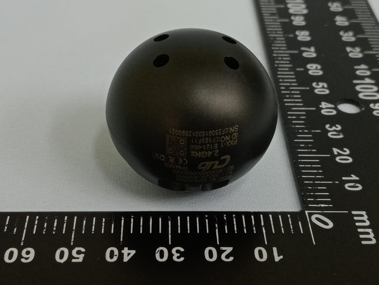
ZPNTPM208
Nov 24, 2025TPMS TRK 2.4G Orb Sensor (
Equipment Class
DTS - Digital Transmission System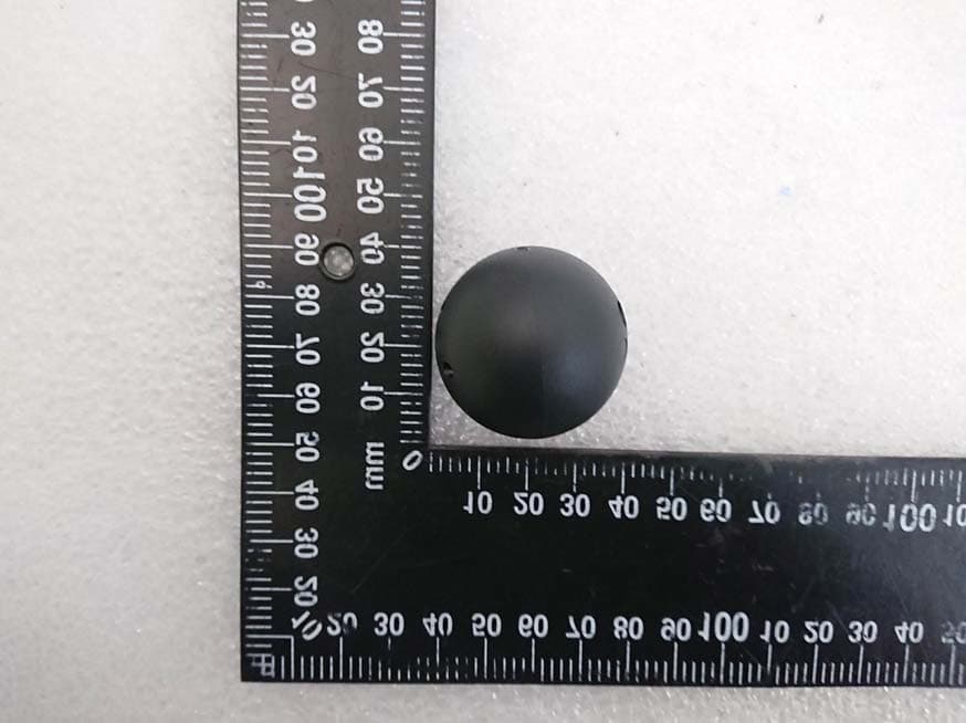
ZPNTPM201
Jun 03, 20212.4 GHz Ball Sensor
Equipment Class
DTS - Digital Transmission System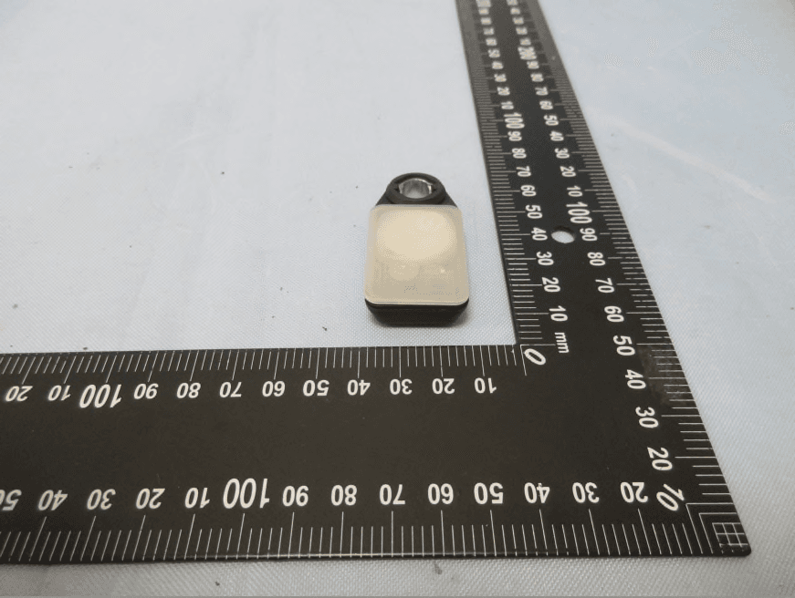
ZPNTPM202
Sep 23, 2020TPMS SENSOR
Equipment Class
DTS - Digital Transmission System
ZPNTPM101
Sep 14, 2020433 MHz Ball Sensor
Equipment Class
DXX - Part 15 Low Power Communication Device Transmitter