ZPNVS63W011Bluetooth Low Energy TPMS Retrofit Kit
CUB ELECPARTS INC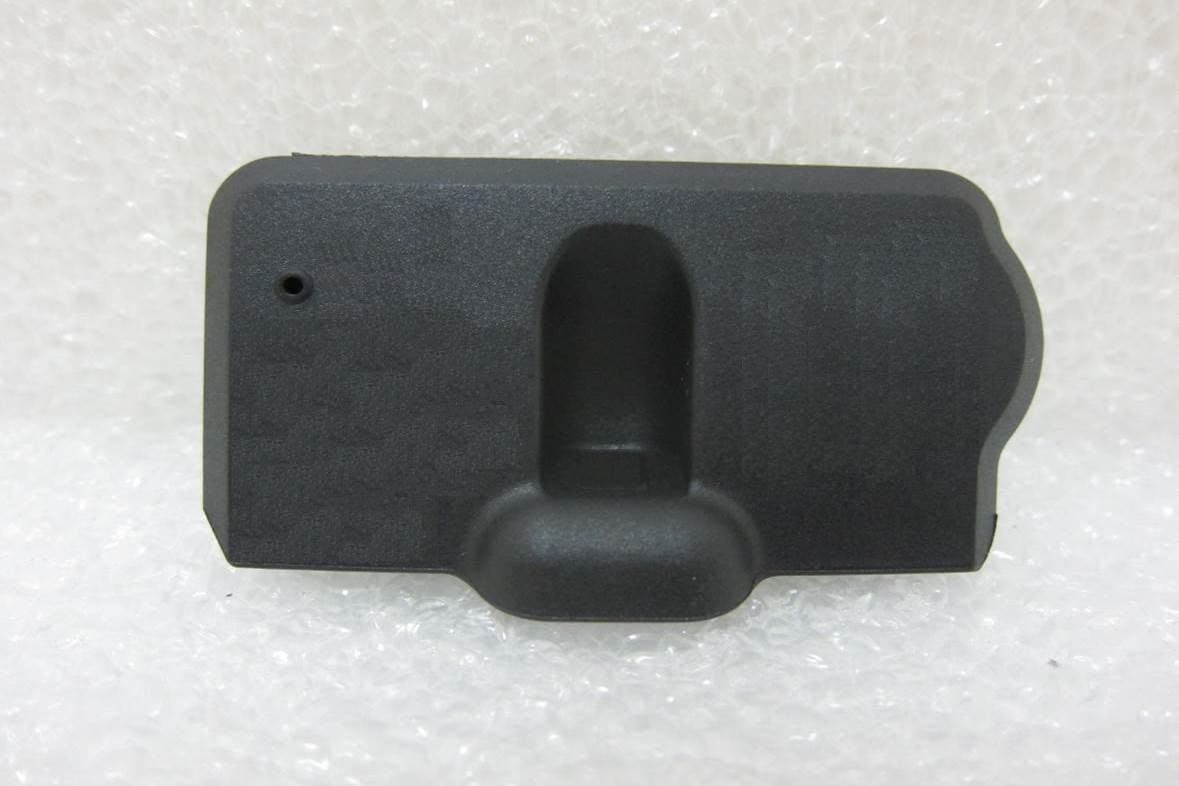
Click to zoom
Application Details
- Equipment Class
- DTS - Digital Transmission System
- Date of Grant
- Dec 07, 2014
- Application Purpose
- Original Equipment
- Date of Application
- Dec 06, 2014
- Equipment Note
- Bluetooth Low Energy TPMS Retrofit Kit
- Frequency Range
- 2402.00000000 - 2480.00000000
- Company
- CUB ELECPARTS INC
- Country
- Taiwan
Documents & Files
Document Text
Text extracted from the exhibit documents filed with the FCC. Open a document above to read the original.
Users Manual
Documents Title Rev V1.3 BLE Tire Pressure Monitoring System User Manual Date Jul 9, 2014 Page 1/13 1 Bluetooth Low Energy TPMS Retrofit Kit User Manual Version 1.3 Prepared By: Approved By: Documents Title Rev V1.3 BLE Tire Pressure Monitoring System User Manual Date Jul 9, 2014 Page 2/13 2 Table of Contents 1. PRODUCT INTRODUCTION .................................................................... 3 2. NOTICE .................................................................................................... 3 3. BLE TPMS SPECIFICATION ................................................................... 4 4. BLE TPMS PACKAGE ............................................................................. 5 5. BLE TPMS SENSOR INSTALLATION ..................................................... 5 6. APP DOWNLOAD AND INSTALLATION ................................................. 6 7. LEARNING SETTING .............................................................................. 7 8. SYSTEM SETTING .................................................................................. 9 9. EXCHANGE SETTING ............................................................................10 10. ALARMS AND WARNING ......................................................................11 11. ABOUT COMPANY INFORMATION .......................................................12 12. WARRANTY POLICY ..............................................................................13 Documents Title Rev V1.3 BLE Tire Pressure Monitoring System User Manual Date Jul 9, 2014 Page 3/13 3 1. Product Introduction Bluetooth Low Energy Tire Pressure Monitoring System Retrofit Kit (hereinafter referred to as BLE TPMS), driver could get the real-time tire pressure and temperature through smart phone in driving by using this kit. When the system detects the abnormal status, it will alarm to driver actively, and show the abnormal data and its tire location on BLE TPMS APP (hereinafter referred to as APP). BLE TPMS includes four sensors, it could be connected wirelessly with your smart phone by Bluetooth technology. The BLE TPMS sensor could detect the tire data and transmit it to the connected smart phone, it shows the tire data of corresponding tire on BLE TPMS APP and driver could access the data in real time. 2. Notice 2.1 Federal Communications Commission (FCC) Statement You are cautioned that changes or modifications not expressly approved by the part responsible for compliance could void the user’s authority to operate the equipment. This device complies with Part 15 of the FCC Rules. Operation is subject to the following two conditions: 1) This device may not cause harmful interference, and 2) This device must accept any interference received, including interference that may cause undesired operation of the device. This equipment has been tested and found to comply with the limits for a Class B digital device, pursuant to part 15 of the FCC rules. These limits are designed to provide reasonable protection against harmful interference in a residential installation. This equipment generates, uses and can radiate radio frequency energy and, if not installed and used in accordance with the instructions, may cause harmful interference to radio communications. However, there is no guarantee that interference will not occur in a Documents Title Rev V1.3 BLE Tire Pressure Monitoring System User Manual Date Jul 9, 2014 Page 4/13 4 particular installation. If this equipment does cause harmful interference to radio or television reception, which can be determined by turning the equipment off and on, the user is encouraged to try to correct the interference by one or more of the following measures: -Reorient or relocate the receiving antenna. -Increase the separation between the equipment and receiver. -Connect the equipment into an outlet on a circuit different from that to which the receiver is connected. -Consult the dealer or an experienced radio/TV technician for help. FCC RF Radiation Exposure Statement: This equipment complies with FCC radiation exposure limits set forth for an uncontrolled environment. End users must follow the specific operating instructions for satisfying RF exposure compliance. This transmitter must not be co-located or operating in conjunction with any other antenna or transmitter. 2.2 Product Warning 2.2.1 Do not operate APP while driving, the company is exempt from all consequences because of driver’s careless and improper operation. 2.2.2 The system adopts the wireless transmission of signals. In some special environment, frequency interference or wrong operation or wrong installation may cause signal weaker or no signal. If the insulation adhesive sticker of the windshield contains metal material, it will affect signal reception. When it alarms sound and shows abnormal data, please drive the vehicle away from the current location (there may be signal interference in the neighborhood) or drive the vehicle to a tire shop to check. 2.2.3 The battery status of the TPMS sensor is low (abnormal condition exists, the battery may make the TPMS sensors continuously emit signals to warn the driver, so that battery life is shorter than expected life), please go as soon as possible to the specified service station to confirm whether the TPMS sensor need to be replaced. 2.2.4 Please change the battery while battery power is low, and change the sensor while low sensor battery warning is alarmed, it may cause the TPMS not working normally. You will take all risks and responsibilities for this! 2.2.5 Temporary resealing or re-inflation product injected through valve hole may adversely affect the operation of the sensor. The company is exempt from all consequences 2.2.6 Do not place the TPMS sensor in contact with chemicals, it would cause sensor damaged and cannot function properly. 2.2.7 Please close the other APPs or web pages which are not in use when using BLE APP, data receiving condition on APP will probably be af…
Text truncated - open the document above for the full version.
External Photos
FCC ID: ZPNVS63W011 International Standards Laboratory Report Number: ISL-14LR171FC EXTERNAL PHOTOGRAPHS OF EUT FCC ID: ZPNVS63W011 International Standards Laboratory Report Number: ISL-14LR171FC EUT 1 EUT 2 FCC ID: ZPNVS63W011 International Standards Laboratory Report Number: ISL-14LR171FC EUT 3
Internal Photos
FCC ID: ZPNVS63W011 International Standards Laboratory Report Number: ISL-14LR171FC INTERNAL PHOTOGRAPHS OF EUT FCC ID: ZPNVS63W011 International Standards Laboratory Report Number: ISL-14LR171FC EUT 1 EUT 2 FCC ID: ZPNVS63W011 International Standards Laboratory Report Number: ISL-14LR171FC EUT 3 BT Antenna
RF Exposure Info
FCC ID: ZPNVS63W011 International Standards Laboratory 1 RF EXPOSURE 1.1 Standard Applicable According to§2.1093 this is a Portable device. For The radiation source included into the device the output power is taken from a corresponding RF test report. If needed the output power is converted to source based, time – average out power. Finally the output power is compared to FCC and IC low power SAR evaluation exemption level. FCC SAR test exclusion: According to KDB 447498 D01 General RF Exposure Guidance v05r02, Appendix A requirement, “The equation and threshold in section 4.3.1 must be applied to determine SAR test exclusion.” 4.3.1. Standalone SAR test exclusion considerations Unless specifically required by the published RF exposure KDB procedures, standalone 1-g head or body and 10-g extremity SAR evaluation for general population exposure conditions, by measurement or numerical simulation, is not required when the corresponding SAR Test Exclusion Threshold condition, listed below, is satisfied. These test exclusion conditions are based on source-based time-averaged maximum conducted output power of the RF channel requiring evaluation, adjusted for tune-up tolerance, and the minimum test separation distance required for the exposure conditions.23 The minimum test separation distance is determined by the smallest distance from the antenna and radiating structures or outer surface of the device, according to the host form factor, exposure conditions and platform requirements, to any part of the body or extremity of a user or bystander (see 5) of section 4.1). To qualify for SAR test exclusion, the test separation distances applied must be fully explained and justified by the operating configurations and exposure conditions of the transmitter and applicable host platform requirements, typically in the SAR measurement or SAR analysis report, according to the required published RF exposure KDB procedures. When no other RF exposure testing or reporting is required, a statement of justification and compliance must be included in the equipment approval, in lieu of the SAR report, to qualify for the SAR test exclusion. When required, the device specific conditions described in the other published RF exposure KDB procedures must be satisfied before applying these SAR test exclusion provisions; for example, handheld PTT two-way radios, handsets, laptops & tablets etc.24 1) The 1-g and 10-g SAR test exclusion thresholds for 100 MHz to 6 GHz at test separation distances ≤ 50 mm are determined by: FCC ID: ZPNVS63W011 International Standards Laboratory [(max. power of channel, including tune-up tolerance, mW)/(min. test separation distance, mm)] · [√f(GHz)] ≤ 3.0 for 1-g SAR and ≤ 7.5 for 10-g extremity SAR,25 where • f(GHz) is the RF channel transmit frequency in GHz • Power and distance are rounded to the nearest mW and mm before calculation26 • The result is rounded to one decimal place for comparison • 3.0 and 7.5 are referred to as the numeric thresholds in the step 2 below The test exclusions are applicable only when the minimum test separation distance is ≤ 50 mm and for transmission frequencies between 100 MHz and 6 GHz. When the minimum test separation distance is < 5 mm, a distance of 5 mm according to 5) in section 4.1 is applied to determine SAR test exclusion. 1.2 Measurement Result: Frequency (MHz) Max power (dBm) Antenna Gain(dBi) EIRP Power (dBm) tune-up tolerance (dB) Max power (mW) Min Distance (mm) Result Limit (3.0 @ 1g SAR ) 24020.152.822.9723.1405095.000.9733.0 24400.382.823.2023.3113115.001.0343.0 24800.422.823.2423.3419505.001.0533.0 Max Power(mW) =10^((Max Power(dBm) + Tune-up tolerance(dB) )/10) Result = Max Power (mW) / min. distance(mm) * √f(GHz) The SAR measurement is not necessary.
Test Report
Page: 1 of 39 TEST REPORT of FCC Part 15 Subpart C New Application; Class I PC; Class II PC Product : Bluetooth Low Energy TPMS Retrofit Kit Brand: Cub Model: VS-63W011 Model Difference: N/A FCC ID: ZPNVS63W011 FCC Rule Part: §15.247, Cat: DTS Applicant: CUB ELECPARTS INC Address: No. 6, Lane 546, Sec. 6, Changlu Road, Fuhsin Township, Changhua County, Taiwan Test Performed by: International Standards Laboratory <Lung-Tan LAB> *Site Registration No. BSMI: SL2-IN-E-0013; MRA TW1036; TAF: 0997; IC: IC4067B-3; *Address: No. 120, Lane 180, San Ho Tsuen, Hsin Ho Rd. Lung-Tan Hsiang, Tao Yuan County 325, Taiwan *Tel : 886-3-407-1718; Fax: 886-3-407-1738 Report No.: ISL-14LR171FC Issue Date : 2014/11/20 Test results given in this report apply only to the specific sample(s) tested and are traceable to nation- al or international standard through calibration of the equipment and evaluating measurement uncertainty herein. This report MUST not be used to claim product en- dorsement by TAF, NVLAP or any agency of the Government. This test report shall not be reproduced except in full, without the written approval of International Standards Laboratory. -2 of 39- FCC ID: ZPNVS63W011 International Standards Laboratory Report Number: ISL-14LR171FC VERIFICATION OF COMPLIANCE Applicant: CUB ELECPARTS INC Product Description: Bluetooth Low Energy TPMS Retrofit Kit Brand Name: Cub Model No.: VS-63W011 Model Difference: N/A FCC ID: ZPNVS63W011 Date of test: 2014/06/30 ~ 2014/11/12 Date of EUT Received: 2014/06/30 We hereby certify that: All the tests in this report have been performed and recorded in accordance with the standards de- scribed above and performed by an independent electromagnetic compatibility consultant, Interna- tional Standards Laboratory. The test results contained in this report accurately represent the measurements of the characteristics and the energy generated by sample equipment under test at the time of the test. The sample equip- ment tested as described in this report is in compliance with the limits of above standards. Test By: Date: 2014/11/20 Dion Chang / Engineer Prepared By: Date: 2014/11/20 Eva Kao / Asst. Supervisor Approved By: Date: 2014/11/20 Vincent Su / Technical Manager -3 of 39- FCC ID: ZPNVS63W011 International Standards Laboratory Report Number: ISL-14LR171FC Version Version No. Date Description 00 2014/11/20 Initial creation of document -4 of 39- FCC ID: ZPNVS63W011 International Standards Laboratory Report Number: ISL-14LR171FC Table of Contents 1 GENERAL INFORMATION .................................................................................................... 6 1.1 Related Submittal(s) / Grant (s) ..................................................................................................... 7 1.2 Test Methodology .......................................................................................................................... 7 1.3 Test Facility .................................................................................................................................... 7 1.4 Special Accessories ........................................................................................................................ 7 1.5 Equipment Modifications ............................................................................................................... 7 2 SYSTEM TEST CONFIGURATION ....................................................................................... 8 2.1 EUT Configuration ........................................................................................................................ 8 2.2 EUT Exercise ................................................................................................................................. 8 2.3 Test Procedure ................................................................................................................................ 8 2.4 Configuration of Tested System ..................................................................................................... 9 3 SUMMARY OF TEST RESULTS .......................................................................................... 10 4 DESCRIPTION OF TEST MODES ....................................................................................... 10 5 CONDUCTED EMISSION TEST........................................................................................... 11 5.1 Standard Applicable: .................................................................................................................... 11 5.2 Measurement Equipment Used: ................................................................................................... 11 5.3 EUT Setup: ................................................................................................................................... 11 5.4 Measurement Procedure: ............................................................................................................. 12 5.5 Measurement Result: ................................................................................................................... 12 6 PEAK /AVERAGE OUTPUT POWER MEASUREMENT................................................. 13 6.1 Standard Applicable: .................................................................................................................... 13 6.2 Measurement Equipment Used: ................................................................................................... 14 6.3 Test Set-up: .................................................................................................................................. 14 6.4 Measurement Procedure: ............................................................................................................. 14 6.5 Measurement Result: ................................................................................................................... 14 7 6dB Bandwidth(EBW) ...............................…
Text truncated - open the document above for the full version.
Test Setup Photos
FCC ID: ZPNVS63W011 International Standards Laboratory Report Number: ISL-14LR171FC PHOTOGRAPHS OF SET UP FCC ID: ZPNVS63W011 International Standards Laboratory Report Number: ISL-14LR171FC Radiated Emission Set up Photo FCC ID: ZPNVS63W011 International Standards Laboratory Report Number: ISL-14LR171FC
Contact Information
Applicant
June Wu(Quality System Dept. / Administrator)
Test Firm
International Standards Laboratory Corp.Benson Chen
Technical Specifications
| # | Rule Parts | Frequency Range | Power Output |
|---|---|---|---|
| 1 | 15C | 2.40 GHz - 2.48 GHz | 1.00 mW |
Other Applications from CUB ELECPARTS INC
ZPNB122110
Jan 16, 2026mmWave Radar
Equipment Class
VRD - Part 95 Vehicular Radar Systems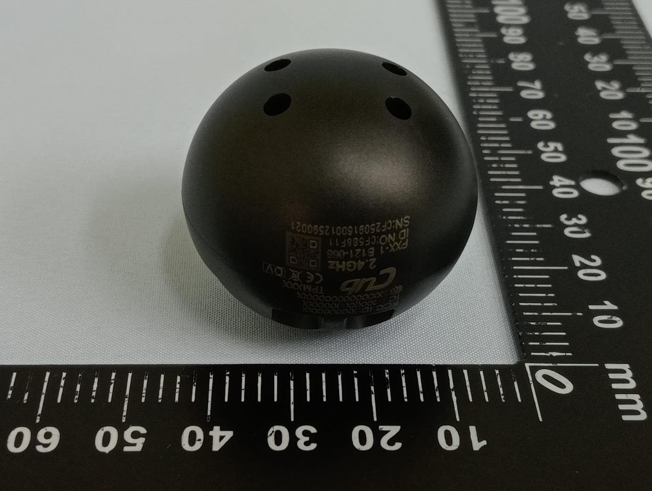
ZPNTPM208
Nov 24, 2025TPMS TRK 2.4G Orb Sensor (
Equipment Class
DTS - Digital Transmission System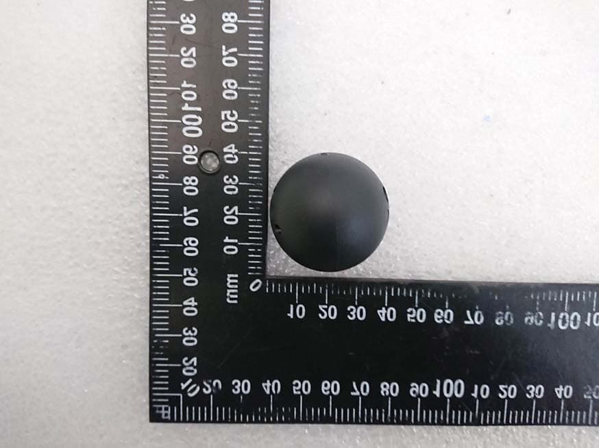
ZPNTPM201
Jun 03, 20212.4 GHz Ball Sensor
Equipment Class
DTS - Digital Transmission System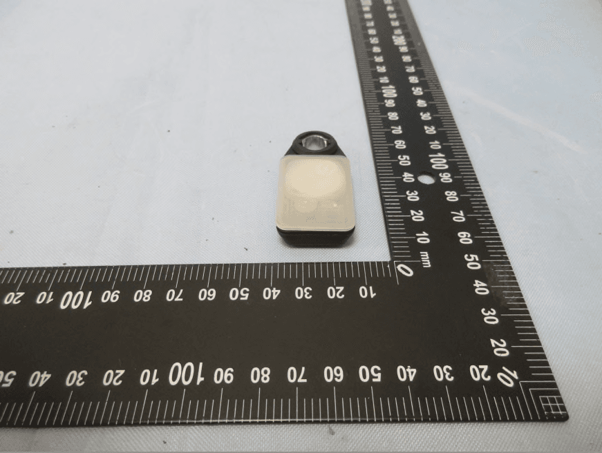
ZPNTPM202
Sep 23, 2020TPMS SENSOR
Equipment Class
DTS - Digital Transmission System
ZPNTPM101
Sep 14, 2020433 MHz Ball Sensor
Equipment Class
DXX - Part 15 Low Power Communication Device Transmitter