ZW5007HEAD-MOUNT DISPLAY SYSTEM FOR SPORT GOGGLES
Recon Instruments, Inc.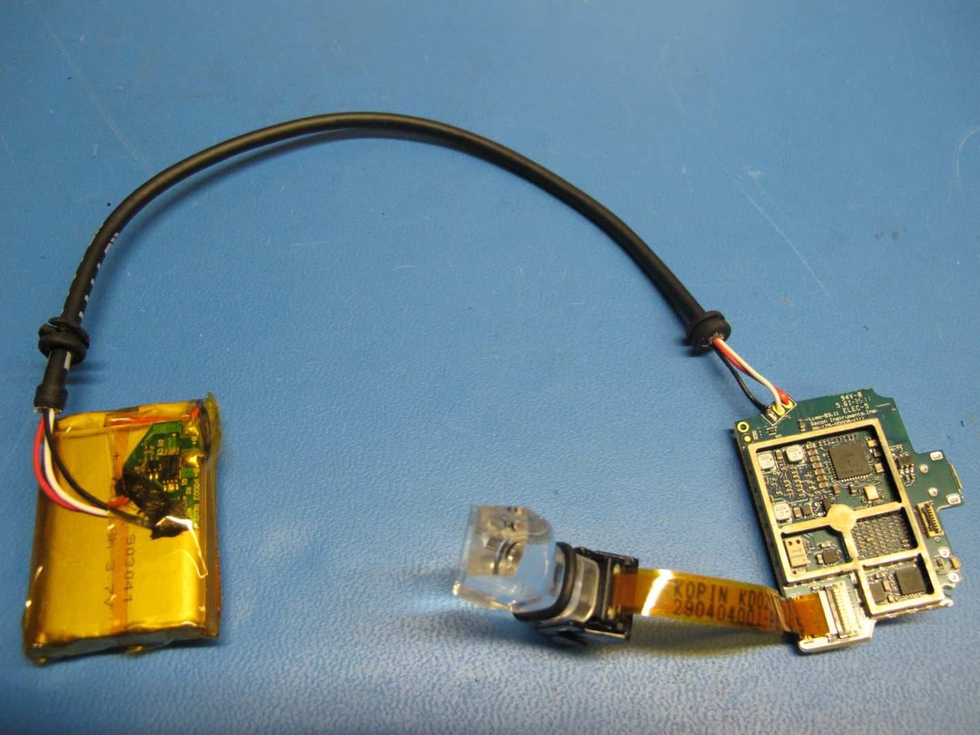
Click to zoom
Application Details
- Equipment Class
- DXX - Part 15 Low Power Communication Device Transmitter
- Date of Grant
- Nov 28, 2011
- Application Purpose
- Original Equipment
- Date of Application
- Nov 28, 2011
- Equipment Note
- HEAD-MOUNT DISPLAY SYSTEM FOR SPORT GOGGLES
- Frequency Range
- 2402.00000000 - 2480.00000000
- Company
- Recon Instruments, Inc.
- Country
- Canada
Documents & Files
Document Text
Text extracted from the exhibit documents filed with the FCC. Open a document above to read the original.
Users Manual
Mod Live User Guide Document Type / User Guide Group / Marketing Document ID / x Authors /David Lee, Ingrid Schneller Version # Implemented By Revision Date Approved By Approval Date Reason 0.1 David Lee 2011/5/05 Initial Draft 0.2 David Lee 2011/6/03 Phone, popups, safety 0.3 David Lee 2011/8/16 0.4 David Lee 2011/9/01 Updating to latest GUI design 0.5 Ingrid Schneller 2011/10/26 Updating after testing to latest UI and features Page 2 of 45 WHAT’S IN THE BOX Your MOD Live box includes the following components: Micro-optic display and battery pack. This snaps into your goggles. Bluetooth remote control. This lets you control the micro-optic display. Goggle strap. This attaches the remote control to your goggle. Wrist strap. This attaches the remote control to your wrist, jacket, backpack, or belt. AC Adapters. Includes two types of adapters (North American and European) for charging the battery on the micro-optic display. Micro USB cable. This lets you connect MOD Live to an AC adapter or to your computer for charging. Kirill: this is a good location for a detailed illustration or photo that has callouts to the main parts. We should identify the power button, the battery pack, the micro- optic “head” etc. SAFETY INFORMATION MOD LIVE uses Bluetooth low energy to communicate with the wireless remote controller. Follow these safety guidelines: ROAD SAFETY COMES FIRST. To avoid distraction, turn off MOD Live before you drive. Never use the remote controller while driving: keep your hands free. SWITCH OFF IN HOSPITALS AND AROUND MEDICAL DEVICES. Wireless devices can cause interference with medical equipment. Keep MOD Live turned off around medical equipment. Follow any restrictions posted in hospitals and health centers. If you wear a pacemaker, check with the manufacturer on SWITCH OFF IN AIRCRAFT. Keep MOD Live turned off around helicopters or aircraft. Follow any restrictions posted in helipads and airports. SWITCH OFF NEAR BLASTING. Keep MOD Live turned off in areas where blasting is in progress. SWITCH BEFORE REFUELLING. Keep MOD Live turned off at gas stations, refuelling areas or in areas where fuel and volatile chemicals such as propane are stored. EYE SAFETY TIPS MOD Live displays a virtual image focused five feet away from your eye. If you experience nausea or eye strain when using MOD Live, take a break for several minutes. Avoid wearing eyeglasses under your goggles. Page 3 of 45 SETUP INSTRUCTIONS STEP 1. GOGGLE SETUP Only use goggles that are Recon-Ready®. 2011 Recon Ready™ partners include: Uvex®, Briko®, Zeal®, and Alpina®. Learn more about Recon-Ready goggles at http://www.ReconReady.com 1) Remove the lens from the goggle frame. See instructions provided by the goggle manufacturer. 2) On the frame of your goggles, remove the protective badge from the left side of the frame. This will reveal slots for MOD Live to be inserted. 3) Next, insert MOD Live into the goggle frame as follows: with the goggles facing you, snap the MOD Live micro optics display unit into the left inner corner of the frame. Next, insert the battery pack into the right corner. 4) Push the MOD Live cable into the groove so that it fits tightly. 5) If the cable is too short, tug it gently so the white stripes appear. If the cable is too long, push it back in. 6) Insert the lens back into the goggles. Take care not to touch or smudge the lens. STEP 2. CHARGE UP MOD LIVE NOTE: Always use the Recon AC adapter and USB cable shipped with your unit. Never use third-party cables or adapters. To fully charge MOD Live using an AC adapter: Kirill: insert an illustration that shows the red light (for example, from step 8 of the 1) Make sure MOD Live is turned off before you start. Kirill: insert an illustration that shows power button 2) Assemble the AC adapter by inserting the North American or European plug. 3) Insert the large plug of the USB cable into the adapter port. 4) Pop open the cover of MOD Live’s USB port. Tip: the port cover shows a tiny image of a USB cable. Insert the smaller plug into MOD Live’s USB port. Check that the plug’s 7L lettering appears on the outside of the goggle. 5) Plug the adapter into a power outlet. When MOD Live begins charging, a red light appears directly above the USB port. If the battery was drained after the unit left the factory, it can take up to 3 hours for the battery to become fully charged. Page 4 of 45 6) After the red light disappears, disconnect the adapter. Remove the USB cable from MOD Live. 7) Replace the plastic USB port cover to ensure the port is protected from rain, snow and ice. To charge up using a PC or Mac Kirill: insert an illustration that shows the red light (for example, from step 8 of the quick start guide) 1) Make sure MOD Live is turned off before you start. 2) Turn on your PC or Mac. Make sure the computer is not in standby mode. 3) Find the MOD Live power button located next to the micro USB port. Hold down the power button for 3 seconds. Kirill: insert an illustration of the power button. 4) Plug the micro USB cable’s smaller end into MOD Live’s micro USB port. 5) Plug the USB cable’s larger end into the USB port in your PC or Mac. When MOD Live begins charging, a red light appears directly above the USB port. 6) Wait for the red light to disappear. 7) Navigate to “safely remove or eject the hardware” using your PC or Mac before you disconnect the USB cable from MOD Live. 8) Disconnect the adapter. 9) Remove the USB cable and seal the micro USB tightly. Use the plastic USB port cover to ensure the port is protected from rain, snow and ice. NOTE: In optimal conditions, MOD Live can achieve a fast charge (80% of battery) using your computer or AC adapter in 1 hour. MOD Live can be fully charged in 3 hours. For more information, see the section BATTERY CARE, later in this guide. STEP 3. CHECK THE REMOTE CONTROLLER Although MOD live is factory-paired (synchronized) with the remote controller shipped in the box, follow these instructions …
Text truncated - open the document above for the full version.
Cover Letter(s)
r0con INSTRUMENTS ReconInstrumentsInc. 220-1050HomerStreet,Vancouver,BCV6B2W9,Canada Tel+16046381608 WWW,i'cconinstrumcntf:LCnm FederalCommunicationsCommissions Date:3 rd November2011 Re: ConfidentialityRequestregardingthe applicationof FCCID: ZW5007 DearSir/Madam: Pursuanttosections0.457and0.459oftheCommission'sRules,weherebyrequestconfidential treatmentofinformationaccompanyingthisapplicationasoutlinedbelow: ExhibitFileName MODLive-Schematics.pdf MODLive-BOM.pdf MODLive-BlkDia.pdf Schematics PartList BlockDiagram Theabovematerialscontaintradesecretsandproprietaryinformationandtheyshouldnotbe customarilyreleasedtothepublic.Thepublicdisclosureofthesematerialsmaybeharmfultothe applicantandprovideunjustifiedbenefitstoitscompetitors. TheapplicantunderstandsthatpursuanttoSection0.457oftheRules,disclosureofthisapplicationand allaccompanyingdocumentationwillnotbemadebeforethedateofthegrantoftheapplication. Sincerely HamidAbdollahi,ChiefTechnologyOfficer
External Photos
1) Fully assembled Mod Live inside of Recon-Ready sport goggle. 2) Close up of the MOD Live module inside the goggle with glass removed. 3) Close up of the complete MOD Live module, with all covers on, outside of the goggle. 4) Close up of the complete unit outside of the goggles with the black covers off showing internal battery compartment, Display compartment and processor compartment Front view 5) Close up of the complete unit outside of the goggles with the black covers off showing internal battery compartment, Display compartment and processor compartment back view 6) Front view close-up of processor compartment with RF shields removed 7) back view 8) Close up of display compartment Front View 9) Close-up Back view of display 10) Close up of battery compartment Front View 11) Close-up of battery compartment back view
Internal Photos
1) Fully assembled Mod Live inside of Recon-Ready sport goggle. 2) Close up of the MOD Live module inside the goggle with glass removed. 3) Close up of the complete MOD Live module, with all covers on, outside of the goggle. 4) Close up of the complete unit outside of the goggles with the black covers off showing internal battery compartment, Display compartment and processor compartment Front view 5) Close up of the complete unit outside of the goggles with the black covers off showing internal battery compartment, Display compartment and processor compartment back view 6) Front view close-up of processor compartment with RF shields removed 7) back view 8) Close up of display compartment Front View 9) Close-up Back view of display 10) Close up of battery compartment Front View 11) Close-up of battery compartment back view
Operational Description
Operation of the Bluetooth Transmitters inside the MOD Live module 1. Operation of the Bluetooth (BT) Transmitter The main function of the BT transceiver is to receive or transmit data from other BT devices such as cell phones and video camera. The BT transmitter in MOD Live has a power class 2 RF power as outlined in the Bluetooth V4.0 Specifications, and its limited output is about 0 dBm (1 mW) at the BT antenna’s input. A BT transceiver is operating in a spread spectrum technique which utilizes a pseudorandom frequency hopping scheme with a hopping rate of 1600 hops per second over 78 channels. The channel bandwidth is 1 MHz over the frequency range from 2402 to 2480 MHz. The transmitter’s carrier is modulated with digital modulation methods. Basically, the BT transceiver has three different data transfer rate – 1, 2 and 3-Mbps, depending on the type of data being used. The GSFK (Gaussian Frequency Shift Key) is implemented for the 1-Mbps data, π/4-DQPSK (Differential encoded Phase Shift Keying) for 2-Mbps data, and 8-ary PSK for the 3-Mbps data. 2. Operation of the Bluetooth Low Energy (BLE) Transmitter The function of the BLE transceiver in MOD Live is used to receive control signals from a Recon remote control to navigate the MOD Live’s manual on the display. The BLE transmitter in MOD Live transmits with RF power of about +2 dBm (1.6 mW) at the BT antenna’s input. The BLE transmitter operates with a frequency hopping scheme in pseudorandom patterns over 40 channels (2402 to 2480 MHz). Each channel occupies a 1-MHz bandwidth and is 2 MHz apart from the adjacent channels. The only modulation scheme used is GFSK.
Test Report
CANADA: 16 - 211 Schoolhouse Street Coquitlam, British Columbia Canada V3K 4X9 TEST REPORT IC/FCC IC RSS-Gen Issue 3 and RSS-210 Issue8 FCC 47CFR Part 15/C Section 15.249 Transmitter Intentional Radiator Report Reference No. ................. ... : E10415-1108 Issue: ............................................................: Original - Rev 1.0 Date of issue .......................................... .........: 2011-11-08 Total number of pages. . . . . . . . . . . . . . . . : 43 Testing Laboratory.................................. : Quality Auditing Institute Address................................................................................................................................... : 16 – 211 Schoolhouse Street, Coquitlam, BC, V3K 4X9, Canada Accreditations.........................: IAS ISO17025 Accredited Laboratory No TL-239 This report has been completed in accordance with the requirements of ISO/IEC 17025. Test results contained in this report are with in QAI Laboratories ISO/IEC 17025 accreditation. QAI Laboratories authorizes the applicant to reproduce this report provided it is reproduced entirely and for the use by company’s employees only. Applicant’s name ............................ : Recon Instruments Inc. Address................................................................................................................................. : 220-1050 Homer St. Vancouver BC, V6B 2W9, Canada Contact................................................................................................................................. : Hamid Abdollahi [email protected] Industry Canada Registration : 9717A-007 FCC Registration: ZW5007 Test specification: Standard........................................... : RSS-Gen; RSS-210; FCC Part 15.249 Test procedure ................................. : RSS-Gen; FCC Part15/C; ANSI C63.4-2009 Non-standard test method..............: N/A CANADA: 16 - 211 Schoolhouse Street Coquitlam, British Columbia Canada V3K 4X9 Test item description..................... : Head-mounted display system with GPS and Bluetooth for Recon Ready sport goggles. Trade Mark....................................... : N/A Manufacturer .................................... : Recon Instruments Inc. Model/Type reference ...................... : RI- MOD-L Ratings ............................................. : +5Vdc Rechargeable Battery – charged by 100-240Vac 50-60Hz adapter via mini-USB cable Testing procedure and testing location: Testing Laboratory: Quality Auditing Institute Testing location/ address .......................: 16 – 211 Schoolhouse Street, Coquitlam, BC, 3K 4X9, Canada Associated Laboratory: Quality Auditing Institute EMC lab (Remote location) Testing location/ address .......................: 19473 Fraser Way, Pitt Meadows, BC, V3Y 2V4, Canada FCC Test Site Registration Number (OATS 10m and SAC-3m): 226383 Industry Canada Site Registration Number (SAC-3m)............: 9543B-1 Industry Canada Test Site Registration Number (OATS-10m)..: 9543C-1 Testing procedure: Tested by (name + signature)...... : David Johanson Approved by (+ signature) ............: Aman Jathaul Testing location/ address ...............: 19473 Fraser Way, Pitt Meadows, BC, V3Y 2V4, Canada Sample Information: Model Number........................: RI-MOD-L Company:..............................: Recon Instruments Inc. Received Date:........................: October 11, 2011 Received By............................: David Johanson Sample Log.............................: QAI Product Control Log (QM 1301 - Sample Inventory) Environmental Conditions: Day 1: Oct 11-2011 Indoor Temperature: 22ºC R.H.: 39% Day 2: Oct 13-2011 Indoor Temperature: 21ºC R.H.: 45% Day 3: Oct 14-2011 Indoor Temperature: 19ºC R.H.: 52% Day 4: Oct 17-2011 Indoor Temperature: 22ºC R.H.: 40% Day 5: Oct 20-2011 Indoor Temperature: 20ºC R.H.: 44% Day 6: Oct 21 2011 Indoor Temperature: 21ºC R.H.: 42% Day 7: Oct 26-2011 Indoor Temperature: 20ºC R.H.: 44% Day 8: Nov 01 2011 Indoor Temperature: 21ºC R.H.: 42% Recon Instruments Inc. Report Number:E10415-1108 Page 4 of 43 The following tests demonstrate the testimony to FCC and IC Electromagnetic compatibility testing for this product. EMISSIONS North America Regions: • CFR 47 Part 15 Subpart B and Subpart C, Section 15.249 • Industry Canada ICES-003, RSS-Gen and RSS-210 Tests were conducted on a sample of the equipment for the purpose of demonstrating compliance with Industry Canada and FCC Regulations for an un-licensed Intentional Radiator. Recon Instruments Inc. is responsible for the tested product configuration, continued product compliance with these standards listed, and for the appropriate auditing of subsequent products, as required. This is to certify that the following report is true and correct to the best of our knowledge. X Tested By David Johanson RF/EMC Test Engineer X Reviewed By Aman Jathaul RF/ EMC Engineer Recon Instruments Inc. Report Number:E10415-1108 Page 5 of 43 Measurement Uncertainty Radio Frequency ....................................................: ±1,5 x 10⁻⁵ Total RF power, conducted....................................: ±1 dB RF power density, conducted.................................: ±2.75 dB Spurious emissions, conducted.............................: ±3 dB All emissions, radiated...........................................: ±3.5 dB Temperature...........................................................: ±1ºC Humidity.................................................................: ±5 % DC and low frequency voltages..............................: ±3 % Test Equipment List Emissions Manufacturer Model Description Serial No. Cal Due Date ETS Lindgren S201 3M Chamber 40GHz 1030 N/R ETS Lindgren Custom Mast with Motor N/R N/R ETS Lindgren Custom Turntable N/R N/R Sunol Sciences JB3 Biconilog Antenna 20MHz-3GHz A120106 28-Oct-2011 Com-Power AHA-118 Horn Antenna 1- 18GHz 711041 11-Mar-2014 Com-Power LI-115 LISN 241036 11-Feb-2012 Rohde…
Text truncated - open the document above for the full version.
Test Setup Photos
Appendix A. EUT photos during the testing Recon Instruments Inc. Report Number:E10415-1108 Page 2 of 3 Recon Instruments Inc. Report Number:E10415-1108 Page 3 of 3
Contact Information
Applicant
Hamid Abdollahi(CTO)
Test Firm
Quality Auditing Institute Ltd.Lawrence Gibson
[email protected]604-527-8378
Technical Specifications
| # | Rule Parts | Frequency Range | Power Output |
|---|---|---|---|
| 1 | 15C | 2.40 GHz - 2.48 GHz | - |
Other Applications from Recon Instruments, Inc.
ZW5009
Feb 18, 2015Heads up display for sports eyewear
Equipment Class
DSS - Part 15 Spread Spectrum Transmitter
ZW5008
Jul 25, 2013Head Mount Dispay System for Sports Goggles
Equipment Class
DTS - Digital Transmission System
ZW5001
Oct 20, 2011REMOTE FOR HEAD MOUNT SPORTS GOGGLE
Equipment Class
DXX - Part 15 Low Power Communication Device Transmitter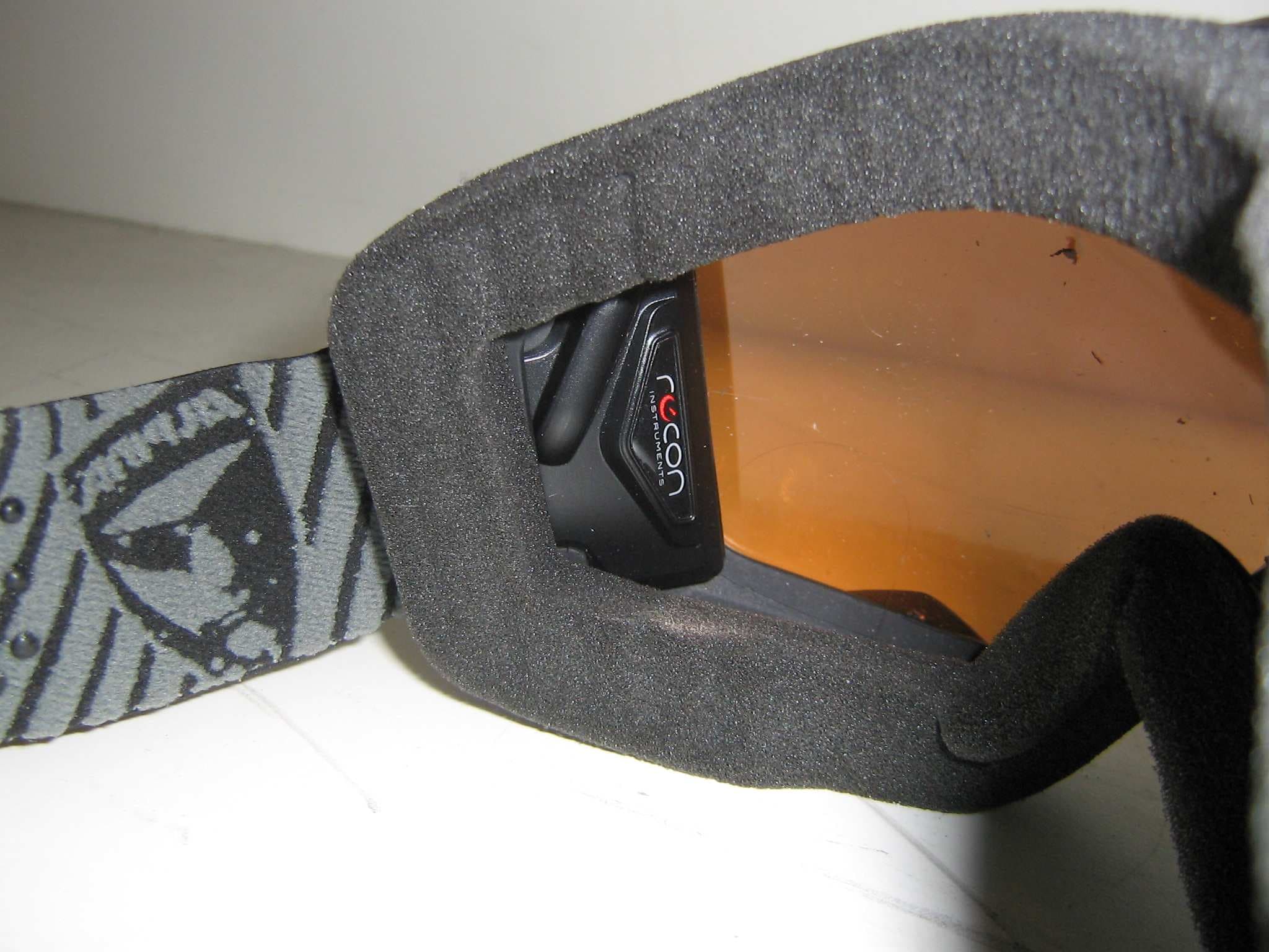
ZW5006
Oct 20, 2011HEAD MOUNT DISPLAY SYSTEM FOR SPORTS GOGGLES
Equipment Class
DXX - Part 15 Low Power Communication Device Transmitter