2A3OONR10Two Way Radio
Shenzhen Ysair Technology Co., LTD
Click to zoom
Application Details
- Equipment Class
- FRF - Part 95 Family Radio Face Held Transmitter
- Date of Grant
- Dec 07, 2022
- Application Purpose
- Original Equipment
- Date of Application
- Dec 07, 2022
- Equipment Note
- Two Way Radio
- Frequency Range
- 462.56250000 - 462.71250000
- Country
- China
Documents & Files
Document Text
Text extracted from the exhibit documents filed with the FCC. Open a document above to read the original.
Users Manual
USER’S MANUAL NR10 Contents -------------------------------------------------------------------------------01 --------------------------------------------------------------01 --------------------------------------------------------------02 -----------------------------------------------------------------------------------02 -------------------------------------------------------------------03 ---------------------------------------------------------------------04 -----------------------------------------------------------------------------05 Warning Charging Precautions Technical Parameters Detail Function Operation Factory Settings WARNING For downloading further resources: Brochures, Software/Firmware, Manual etc, Please contact your direct reseller first OR go to website retevis.com and check “support” in the each product link to download it. NOTE: Please read this manual carefully before using this walkie-talkie. · Do not charge this walkie-talkie in areas where flammable, explosive and radio communication is prohibited (e.g. gas stations, petrol stations, airports, etc.). · Please do not operate this walkie-talkie without a license in areas where government laws prohibit it. · Please make sure the walkie-talkie is protected from sunlight and avoid placing it near any heating equipment. · Make sure that the walkie-talkie is protected from any dust, moisture and splashing water, and that it is placed near any heating equipment. · If the walkie-talkie smells or smokes, remove the battery pack from the walkie-talkie immediately and contact your nearest dealer. · The repair work of this walkie-talkie is in the hands of professional technicians, self disassembly is strictly prohibited. Charging precautions · Please use the charging stand matched to this model for charging. · When charging the whole machine, it is recommended to turn off the intercom first. · In order to get the best battery performance for use, please charge at least 5 hours for the first time. · Do not charge the battery pack for a long time, otherwise it will shorten the life of the battery pack. When the battery is fully charged, please stop charging in time. · This charger only charges the battery pack of this product, please do not charge other battery packs, otherwise it will cause damage to the charger and the battery pack. · The battery pack should be fully charged and placed in a cool, dry place. Do not put it near the fire source or expose it to the sunlight, otherwise there are safety hazards. · It is forbidden to transmit the product during the charging process of the intercom. · It is normal for the battery pack to heat up slightly during the charging process. 01 Technical parameters Detail Charging mode: Walkie-talkie inserted into the charger charging slot, at this time the charger lights up red to indicate the start of charging, the green light is on to indicate that the battery charge has been saturated. Check the walkie talkie before unpack 02 1 2 3 4 5 6 7 8 9 10 11 Frequency range Output power Narrow width channels Working voltage Antenna impedance Charging current Battery capacity Operating temperature Receiving sensitivity Audio output power FRS High2W Low0.5W 12.5KHz 16CH 3.7V DC 50Ω 300mA 1200mAh -10 ~ +50 ≤0.2μv 1W Technical Specifications Name Description Walkie-talkie host Lithium battery pack Charging stand (with USB cable) DC charging head User Manual Quantity 2 2 2 2 1 Packing list (with two supporting products) Antenna Type-C PTT Switch Noise Reduction/ VOX Channel Belt Clip Volume /Power Tx/Rx LED indicator Accessory Port Microphone(Sound input) Speaker(Sound output) Function operation 1. Power on/off 1.1 Turn the power switch clockwise to hear a "ka" to turn on the power. 1.2 Turn the power switch counterclockwise to hear a "ka" to turn off the power. 2. Volume adjustment 2.1 In the receiving state, turn the volume/power switch clockwise to increase the volume. 2.2 In the receiving state, turn the volume/power switch counterclockwise to decrease the volume. 3. Transmitting/Receiving 3.1 In standby mode, press and hold the transmit button (PTT) to transmit the signal of the current channel and the LED lights up in red. 3.2 Release the transmit button (PTT) to receive the signal sent from the same channel, the speaker makes a call sound and the LED lights up in green. NOTE: ● When the walkie-talkie is transmitting, keep the walkie-talkie in a vertical position and keep the microphone 2.5-5 cm away from the mouth. When transmitting, the walkie-talkie is at least 2.5 cm away from your head or body. ● No need to perform multiple on and off actions during use, while adjusting the volume to a level suitable for your hearing. Before talking on the walkie-talkie. ●Please set the frequency point of the transmitter and receiver to the same. ● Please set the sub tone code of transmitter and receiver to be the same for the channel you need to talk to. 4. Channel selection In the standby state, turn the channel knob clockwise and counterclockwise while broadcasting and displaying the current channel number. 5. PTT switch Press the PTT button and speak into the microphone to call the other party, the red light indicates. If this channel is not set to transmit frequency, it will sound a beep and red light is on, when released to receive, if there is a signal, it will light up the green indicator and turn on the speaker. 6. Voice selection Select English, then open the English "voice notification" function, the factory default is English. Voice selection off, the intercom will not send voice notification. When the voice selection Chinese, then open the Chinese "voice notification" function. 7. Noise reduction/VOX key Short press to open/close the noise reduction function, long press to open/close the VOX function. When noise reduction is on, only human voice can be recognized, and information other than human voice is filtered out. VOX control allows you to transmit without pressing the PTT button, only us…
Text truncated - open the document above for the full version.
Cover Letter(s)
Shenzhen Ysair Technology Co., LTD 6/F, building 6, Yunli intelligent park, No. 3, Changfa Middle Road, Yangmei community, Bantian street, Longgang District, Shenzhen, Guangdong, China Agent Authorization Company: Shenzhen Ysair Technology Co., LTD Address: 6/F, building 6, Yunli intelligent park, No. 3, Changfa Middle Road, Yangmei community, Bantian street, Longgang District, Shenzhen, Guangdong, China Product Name: Two Way Radio Model Number(s): NR10 Product Description: Two Way Radio We authorize MiCOM Labs Inc., 575 Boulder Court, Pleasanton, California 94566, USA, to act on our behalf on all matters concerning the certification of above named equipment. We declare that MiCOM Labs Inc. is allowed to forward all information related to the approval and certification of equipment to the regulatory agencies as required and to discuss any issues concerning the approval application. Any and all acts carried out by MiCOM Labs on our behalf shall have the same effect as acts of our own. Signature: Date: Dec. 02, 2022 Name: Weidong Shen Title: General Manager Company: Shenzhen Ysair Technology Co., LTD
Cover Letter(s)
Shenzhen Ysair Technology Co., LTD 6/F, building 6, Yunli intelligent park, No. 3, Changfa Middle Road, Yangmei community, Bantian street, Longgang District, Shenzhen,Guangdong, China Office of Engineering Technology Federal Communications Commission 7435 Oakland Mills Road Columbia, MD 21046 USA Date: Nov. 24, 2022 Subject; Request for Confidentiality FCC ID: 2A3OONR10 To Whom It May Concern, Pursuant to the provisions of the Commission’s rules Title 47 Sections §0.457 and §0.459, we are requesting the Commission to withhold the following attachment(s) as confidential documents from public disclosure indefinitely. These documents contain detailed system and equipment descriptions and are considered as proprietary information in operation of the equipment. The public disclosure of these documents might be harmful to our company and would give competitors an unfair advantage in the market. Schematic Diagram Block Diagram Operational Description Parts List Tune-up Procedure In additional to above mentioned documents, in order to comply with the marketing regulations in Title 47 CFR §2.803 and the importation rules in Title 47 CFR §2.1204, while ensuring that business sensitive information remains confidential until the actual marketing of newly authorized devices, we request Short Term Confidentiality of the following attachment(s); External Photos Test Setup Photos Internal Photos User Manual For 45 days, pursuant to Public Notice DA 04-1705. OR For 180 days pursuant to KDB 726920 D01. It is our understanding that all measurement test reports, FCC ID label format and correspondence during the certification review process cannot be granted as confidential documents and this information will be available for public review once the grant of equipment authorization is issued. Sincerely, Signature: Name: Weidong Shen Title: General Manager
External Photos
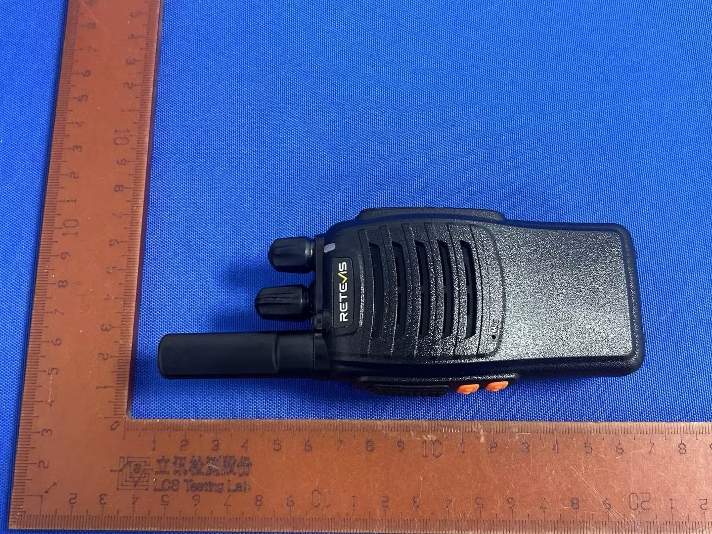
Report No.: AGC13372221102AP02 Page 1 of 7 EXTERNAL PHOTOS All VIEW OF EUT TOP VIEW OF EUT Report No.: AGC13372221102AP02 Page 2 of 7 BOTTOM VIEW OF EUT FRONT VIEW OF EUT Report No.: AGC13372221102AP02 Page 3 of 7 BACK VIEW OF EUT LEFT VIEW OF EUT Report No.: AGC13372221102AP02 Page 4 of 7 RIGHT VIEW OF EUT SERIES MODEL: RT30M TOP VIEW OF EUT Report No.: AGC13372221102AP02 Page 5 of 7 BOTTOM VIEW OF EUT FRONT VIEW OF EUT Report No.: AGC13372221102AP02 Page 6 of 7 BACK VIEW OF EUT LEFT VIEW OF EUT Report No.: AGC13372221102AP02 Page 7 of 7 RIGHT VIEW OF EUT ****************************************End of Report****************************************
ID Label/Location Info
FCC ID Label Location 24.85mm*24.85mm
Internal Photos
Report No.: AGC13372221102AP02 Page 1 of 12 INTERNAL PHOTOS OPEN VIEW OF EUT (FIGURE 1) OPEN VIEW OF EUT (FIGURE 2) Antenna Report No.: AGC13372221102AP02 Page 2 of 12 OPEN VIEW OF EUT (FIGURE 3) INTENAL VIEW OF EUT (FIGURE 1) Report No.: AGC13372221102AP02 Page 3 of 12 INTERNAL VIEW OF EUT (FIGURE 2) INTERNAL VIEW OF EUT (FIGURE 3) Report No.: AGC13372221102AP02 Page 4 of 12 INTERNAL VIEW OF EUT (FIGURE 4) INTERNAL VIEW OF EUT (FIGURE 5) Report No.: AGC13372221102AP02 Page 5 of 12 INTERNAL VIEW OF EUT (FIGURE 6) INTERNAL VIEW OF EUT (FIGURE 7) Report No.: AGC13372221102AP02 Page 6 of 12 INTERNAL VIEW OF EUT (FIGURE 8) INTERNAL VIEW OF EUT (FIGURE 9) Report No.: AGC13372221102AP02 Page 7 of 12 SERIES MODEL: RT30M OPEN VIEW OF EUT (FIGURE 1) OPEN VIEW OF EUT (FIGURE 2) Antenna Report No.: AGC13372221102AP02 Page 8 of 12 OPEN VIEW OF EUT (FIGURE 3) INTENAL VIEW OF EUT (FIGURE 1) Report No.: AGC13372221102AP02 Page 9 of 12 INTERNAL VIEW OF EUT (FIGURE 2) INTERNAL VIEW OF EUT (FIGURE 3) Report No.: AGC13372221102AP02 Page 10 of 12 INTERNAL VIEW OF EUT (FIGURE 4) INTERNAL VIEW OF EUT (FIGURE 5) Report No.: AGC13372221102AP02 Page 11 of 12 INTERNAL VIEW OF EUT (FIGURE 6) INTERNAL VIEW OF EUT (FIGURE 7) Report No.: AGC13372221102AP02 Page 12 of 12 INTERNAL VIEW OF EUT (FIGURE 8) INTERNAL VIEW OF EUT (FIGURE 9) ****************************************End of Report****************************************
RF Exposure Info
Page 1 of 42 SAR Test Report Report No.: AGC13372221101FH01 FCC ID : 2A3OONR10 PRODUCT DESIGNATION : Two Way Radio BRAND NAME : RETEVIS MODEL NAME : NR10 APPLICANT : Shenzhen Ysair Technology Co., LTD DATE OF ISSUE : Nov. 23, 2022 STANDARD(S) : IEEE Std. 1528:2013 FCC 47 CFR Part 2§2.1093 IEEE Std C95.1 ™-2005 IEC 62209-1: 2016 REPORT VERSION : V1.0 Attestation of Global Compliance(Shenzhen) Co., Ltd. Report No.: AGC13372221101FH01 Page 2 of 42 Report Revise Record Report Version Revise Time Issued Date Valid Version Notes V1.0 / Nov. 23, 2022 Valid Initial Release Report No.: AGC13372221101FH01 Page 3 of 42 Test Report Applicant Name Shenzhen Ysair Technology Co., LTD Applicant Address 6/F, building 6, Yunli intelligent park, No. 3, Changfa Middle Road, Yangmei community, Bantian street, Longgang District, Shenzhen, Guangdong, China Manufacturer Name Shenzhen Ysair Technology Co., LTD Manufacturer Address 6/F, building 6, Yunli intelligent park, No. 3, Changfa Middle Road, Yangmei community, Bantian street, Longgang District, Shenzhen, Guangdong, China Product Designation Two Way Radio Brand Name RETEVIS Model Name NR10 EUT Voltage DC 3.7 V by battery Applicable Standard IEEE Std. 1528:2013 FCC 47 CFR Part 2§2.1093 IEEE Std C95.1 ™-2005 IEC 62209-1: 2016 Date of receipt of test item Nov. 02, 2022 Test Date Nov. 23, 2022 Report Template AGCRT- US -PTT/SAR (2021-04-20) Note: The results of testing in this report apply to the product/system which was tested only. Prepared By Thea Huang (Project Engineer) Nov. 23, 2022 Reviewed By Calvin Liu (Reviewer) Nov. 23, 2022 Approved By Max Zhang (Authorized Officer) Nov. 23, 2022 Report No.: AGC13372221101FH01 Page 4 of 42 TABLE OF CONTENTS 1. SUMMARY OF MAXIMUM SAR VALUE ......................................................................................................... 5 2. GENERAL INFORMATION ............................................................................................................................... 6 2.1. EUT DESCRIPTION......................................................................................................................................... 6 3. SAR MEASUREMENT SYSTEM ........................................................................................................................ 7 3.1. THE DASY5 SYSTEM USED FOR PERFORMING COMPLIANCE TESTS CONSISTS OF FOLLOWING ITEMS .................... 7 3.2. DASY5 E-FIELD PROBE ................................................................................................................................. 8 3.3. DATA ACQUISITION ELECTRONICS DESCRIPTION ............................................................................................... 8 3.4. ROBOT .......................................................................................................................................................... 9 3.5. LIGHT BEAM UNIT .......................................................................................................................................... 9 3.6. DEVICE HOLDER .......................................................................................................................................... 10 3.7. MEASUREMENT SERVER ............................................................................................................................... 10 3.8. PHANTOM ................................................................................................................................................. 11 4. SAR MEASUREMENT PROCEDURE ............................................................................................................ 12 4.1. SPECIFIC ABSORPTION RATE (SAR) .............................................................................................................. 12 4.2. SAR MEASUREMENT PROCEDURE ................................................................................................................ 13 5. TISSUE SIMULATING LIQUID ....................................................................................................................... 15 5.1. THE COMPOSITION OF THE TISSUE SIMULATING LIQUID..................................................................................... 15 5.2. TISSUE DIELECTRIC PARAMETERS FOR HEAD AND BODY PHANTOMS ............................................................... 15 5.3. TISSUE CALIBRATION RESULT ....................................................................................................................... 16 6. SAR SYSTEM CHECK PROCEDURE ........................................................................................................... 17 6.1. SAR SYSTEM CHECK PROCEDURES ............................................................................................................. 17 7. EUT TEST POSITION ...................................................................................................................................... 19 7.1. BODY WORN POSITION ................................................................................................................................ 19 8. SAR EXPOSURE LIMITS ............................................................................................................................... 20 9. TEST FACILITY .............................................................................................................................................. 21 10. TEST EQUIPMENT LIST .............................................................................................................................. 22 11. MEASUREMENT UNCERTAINTY ................................................................................................................ 23 12. POWER MEASUREMENT ............................................................................................................................ 27 13. TEST RESULTS ..........................................................................…
Text truncated - open the document above for the full version.
RF Exposure Info
Page 1 of 18 CALIBRATION DATA PROBE CALIBRATION DATA Page 2 of 18 Page 3 of 18 Page 4 of 18 Page 5 of 18 Page 6 of 18 Page 7 of 18 Page 8 of 18 Page 9 of 18 Page 10 of 18 DAE CALIBRATION DATA Page 11 of 18 Page 12 of 18 Page 13 of 18 DIPOLE CALIBRATION DATA Page 14 of 18 Page 15 of 18 Page 16 of 18 Page 17 of 18 Page 18 of 18
Test Report
Page 1 of 34 FCC Test Report Report No.: AGC13372221101FE10 FCC ID : 2A3OONR10 APPLICATION PURPOSE : Original Equipment PRODUCT DESIGNATION : Two Way Radio BRAND NAME : RETEVIS MODEL NAME : NR10 APPLICANT : Shenzhen Ysair Technology Co., LTD DATE OF ISSUE : Nov. 22, 2022 STANDARD(S) : FCC Part 95 Rules REPORT VERSION : V 1.0 Attestation of Global Compliance (Shenzhen) Co., Ltd Report No.: AGC13372221101FE10 Page 2 of 34 REPORT REVISE RECORD Report Version Revise Time Issued Date Valid Version Notes V1.0 / Nov. 22, 2022 Valid Initial Release Report No.: AGC13372221101FE10 Page 3 of 34 TABLE OF CONTENTS 1. GENERAL INFORMATION ........................................................................................................................... 5 2. PRODUCT INFORMATION .............................................................................................................................. 6 2.1 PRODUCT TECHNICAL DESCRIPTION ................................................................................................ 6 2.2 TEST FREQUENCY LIST ........................................................................................................................ 7 2.3 RELATED SUBMITTAL(S) / GRANT (S) ................................................................................................. 8 2.4 TEST METHODOLOGY .......................................................................................................................... 8 2.5 CALCULATION OF EMISSION INDICATORS ........................................................................................ 8 2.6 SPECIAL ACCESSORIES ....................................................................................................................... 8 2.7 EQUIPMENT MODIFICATIONS .............................................................................................................. 8 2.8 ANTENNA REQUIREMENT .................................................................................................................... 9 3. TEST ENVIRONMENT ................................................................................................................................... 10 3.1 ADDRESS OF THE TEST LABORATORY ............................................................................................ 10 3.2 TEST FACILITY ..................................................................................................................................... 10 3.3 ENVIRONMENTAL CONDITIONS......................................................................................................... 11 3.4 MEASUREMENT UNCERTAINTY ........................................................................................................ 11 3.5 LIST OF EQUIPMENTS USED ............................................................................................................. 12 4.SYSTEM TEST CONFIGURATION ................................................................................................................. 13 4.1 EUT CONFIGURATION ......................................................................................................................... 13 4.2 EUT EXERCISE ..................................................................................................................................... 13 4.3 CONFIGURATION OF TESTED SYSTEM ............................................................................................ 13 4.4 EQUIPMENT USED IN TESTED SYSTEM........................................................................................... 13 4.5 SUMMARY OF TEST RESULTS ........................................................................................................... 14 5. DESCRIPTION OF TEST MODES ................................................................................................................. 15 6.FREQUENCY STABILITY ............................................................................................................................... 16 6.1 PROVISIONS APPLICABLE .................................................................................................................. 16 6.2 MEASUREMENT PROCEDURE ........................................................................................................... 16 6.3 MEASUREMENT SETUP ...................................................................................................................... 16 6.4 MEASUREMENT RESULTS.................................................................................................................. 17 7. EMISSION BANDWIDTH ............................................................................................................................... 18 7.1 PROVISIONS APPLICABLE .................................................................................................................. 18 7.2 MEASUREMENT PROCEDURE ........................................................................................................... 18 7.3 MEASUREMENT SETUP ...................................................................................................................... 18 7.4 MEASUREMENT RESULTS.................................................................................................................. 19 8. SPURIOUS RATIATED EMISSION ................................................................................................................. 21 8.1 PROVISIONS APPLICABLE .................................................................................................................. 21 Report No.: AGC13372221101FE10 Page 4 of 34 8.2 MEASUREMENT PROCEDURE ........................................................................................................... 21 8.3 MEASUREMENT SETUP ...................................................................................................................... 22 8.4 MEASUREMENT RESULTS...........................................…
Text truncated - open the document above for the full version.
Test Setup Photos
Report No.: AGC13372221102AP01 Page 1 of 3 TEST SETUP PHOTOS RADIATED EMISSION 30MHz-1GHz TEST SETUP(RSS-210) RADIATED EMISSION ABOVE 1G TEST SETUP(RSS-210) Report No.: AGC13372221102AP01 Page 2 of 3 RADIATED EMISSION 30MHz-1GHz TEST SETUP-RSS-GEN RADIATED EMISSION ABOVE 1G TEST SETUP-RSS-GEN Report No.: AGC13372221102AP01 Page 3 of 3 RF CONDUCTED TEST SETUP ****************************************End of Report*************************************
Contact Information
Applicant
Dongfang Shen(Manager)
Technical Contact
Test Firm
Attestation of Global Compliance (Shenzhen) Co., LDoris Li
[email protected]+86-755-25234088
Technical Specifications
| # | Rule Parts | Frequency Range | Power Output | Emission | Tolerance |
|---|---|---|---|---|---|
| 2 | 95B | 462.5625 MHz - 462.7125 MHz | 968.30 mW | 11K0F3E | 1.08 ppm |
Other Applications from Shenzhen Ysair Technology Co., LTD
2A3OOH777H
Oct 11, 2024Two Way Radio
Equipment Class
FRF - Part 95 Family Radio Face Held Transmitter
2A3OORB48P
Aug 18, 2024Two Way Radio
Equipment Class
TNF - Licensed Non-Broadcast Transmitter Held to Face
2A3OOHS4
Aug 11, 2024Mobile Radio
Equipment Class
CSR - Scanning Receiver
2A3OOHD2
May 20, 2024DMR Digital Transceiver
Equipment Class
DTS - Digital Transmission System
2A3OORTA1
May 01, 2024Amateur Radio
Equipment Class
CSR - Scanning Receiver