2AA9MFGFS101Flood Sensor
Fibar Group S.A.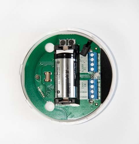
Click to zoom
Application Details
- Equipment Class
- DXT - Part 15 Low Power Transceiver, Rx Verified
- Date of Grant
- Dec 16, 2013
- Application Purpose
- Original Equipment
- Date of Application
- Dec 16, 2013
- Equipment Note
- Flood Sensor
- Frequency Range
- 908.40000000 - 908.40000000
- Company
- Fibar Group S.A.
- Country
- Poland
Documents & Files
Document Text
Text extracted from the exhibit documents filed with the FCC. Open a document above to read the original.
Users Manual
USA OPERATING MANUAL FLOOD SENSOR FGFS-101 v2.1 - v2.3 Fibaro Flood Sensor is a universal, Z-Wave compatible, flood and temperature sensor. Device can be battery (ca. 2 years battery life) or VDC powered (12 or 24 VDC). Flood alarm is sent to the Z-Wave network devices or additionally to any alarm system controller, through opening a NC contact. The device has built in temperature sensor, monitoring temperature of e.g. floor. Fibaro Flood Sensor is designed to be placed on the floor or on a wall with a flood sensor probe extended by connected wire. The device has built in LED indicator and acoustic alarm. In addition, the sensor is equipped with a tilt sensor reporting tilt or movement to the main controller e.g. when someone has taken the Sensor from its original location. LED diode signals flood, operating mode or the Z-Wave network communication range. Fibaro Flood Sensor is sink-proof, which means it drifts on the water surface and keeps on sending alarm signal in case of substantial inundation of water. SPECIFICATIONS Power Supply: Battery Type: Power Consumption (at VDC operation): Output terminals maximum current carrying capacity (ALARM NC, TAMP NC): Maximum voltage at output terminals: EU standards compliance: FCC ID: Radio protocol: Radio frequency: Range: Operational Temperature: Measured temperature range: Temperature measuring accuracy: Dimensions (Diameter x Height): 12 - 24 VDC CR123A 0,4W 25mA 40V (AC or DC) EMC 2004/108/EC R&TTE 199/5/WE 2AA9MFGFS101 Z - Wave 868,4 MHz EU; 908,4 MHz US; 921,4 MHz ANZ; 869,2 MHz RU; up to 50m outdoors up to 30m indoors (Depending on terrain and building structure) 0 - 40 o C* -20 to 100 o C 0,5 o C (within 0 - 40 o C range) 72 x 28 mm AUXCOMZ1Z2 ALARM SYSTEM HUB ALARM NC TA M P NC SENS 1SENS 2+ 12GND TMP Fig. 1 - Connection with alarm system Fig. 3 - Flood sensor’s contacts extended with a wire 12 3 TECHNICAL INFORMATION • Compatible with any Z-Wave network controller, • May be connected to any alarm system (potential free output terminal), • Extremely easy installation - simply put on a surface prone to flooding, • May be installed anywhere - flood sensor’s contacts extended with a wire, • Battery or VDC powered. When connected to an external, VDC power source, the battery serves as an emergency power source, • Theft protection - tilt is reported to the Z-Wave network or alarm system’s main controller, • Two operating modes - flood / temperature sensor or just a temperature sensor. NOTE Connect while observing wiring diagram shown in this manual only. Incorrect wiring may be dangerous or result in the device breakdown. i I. GENERAL INFORMATION ABOUT FIBARO SYSTEM Fibaro is a wireless system, based on Z-Wave technology. Fibaro provides many advantages when compared to similar systems. In general, radio systems create a direct connection between the receiver and transmitter. However, the radio signal is weakened by various obstacles located in its path (apartment walls, furniture, etc.) and in extreme cases it fails to transfer required data. The advantage of Fibaro System is that its devices, apart from being transmitters and signal receivers, also duplicate signal. When a direct connection path between the transmitter and the receiver cannot be established, the connection may be achieved through other intermediate devices. Fibaro is a bi-directional wireless system. This means that the signal is not only sent to the receivers but also the receivers send the confirmation of its reception. This operation confirms their status, which checks whether they are active or not. Safety of the Fibaro System transmission is comparable to the safety of transmission in data bus wired systems. Fibaro operates in the free bandwidth for data transmission. The frequency depends on radio regulations in individual countries. Each Fibaro network has its own unique network identification number (home ID), which is why it is possible to co-operate two or more independent systems in a single building without any interference. Although Z-Wave is quite a new technology, it has already become recognized and officially a binding standard, similarly to Wi-Fi. Many manufacturers in various industries offer solutions based on Z-Wave technology, guaranteeing their compatibility. This means that the system is open and it may be extended in the future. Find more information at www.fibaro.com. Fibaro generates a dynamic network structure. After Fibaro System is switched on, the location of its individual components is automatically updated in real-time through status confirmation signals received from devices operating in a "mesh" network. II. Z-WAVE NETWORK INCLUSION Use TMP button to include the Fibaro Flood Sensor into the Z-Wave network. In addition, the device may be included into the Z-Wave network in auto inclusion mode, at connecting a DC power source (mode active only after the built in battery has been disconnected). Including the Fibaro Flood Sensor using auto inclusion mode: 1) Make sure a DC power source is disconnected and the sensor is located within direct communication with the main controller’s range. The battery must be removed. 2) Open the cover. 3) Set the main controller into the learning mode (see a main controller’s operating manual). 4) Connect a DC power source to include the Fibaro Flood Sensor into the Z-Wave network in autoinclusion mode. 5) Fibaro Flood Sensor will be detected and included. NOTE In case the Sensor is not detected, proceed to the manual inclusion (described below) or reset the Sensor and repeat auto inclusion procedure. i To deactivate auto inclusion mode, press TMP button once, after the Fibaro Flood Sensor has been connected to a DC power supply. Manual Z-Wave network inclusion: 1) Connect a DC power supply to the Fibaro Flood Sensor or insert a battery. Make sure the sensor is located within the Z-Wave network’s main controller’s range (see main controllers operating manual). 2) Set the main controller into the learning mod…
Text truncated - open the document above for the full version.
ID Label/Location Info
Fibaro Flood Sensor FCC Label
Test Report
NVLAP Lab code: 100414-0 FCC 47 CFR PART 15 SUBPART C CERTIFICATION TEST REPORT FOR Flood Sensor MODEL NUMBER: FGFS-101 FCC ID: 2AA9MFGFS101 REPORT NUMBER: 10072441 ISSUE DATE: December 5, 2013 Prepared for Fibar Group sp. z.o.o Ul. Lotnicza 1 Poznań, Poland 60-453 Prepared by UL LLC 333 Pfingsten Rd. Northbrook, IL 60062 TEL: (847) 272-8800 REPORT NO: 10072441 DATE: December 5, 2013 FCC ID: 2AA9MFGFS101 Page 2 of 27 UL LLC FORM NO: CCSUP4701G 333 Pfingsten Rd., Northbrook, IL 60062 TEL: (847) 272-8800 This report shall not be reproduced except in full, without the written approval of UL LLC. Revision History Rev. Issue Date Revisions Revised By -- 12/5/13 Initial Issue M.Ferrer REPORT NO: 10072441 DATE: December 5, 2013 FCC ID: 2AA9MFGFS101 Page 3 of 27 UL LLC FORM NO: CCSUP4701G 333 Pfingsten Rd., Northbrook, IL 60062 TEL: (847) 272-8800 This report shall not be reproduced except in full, without the written approval of UL LLC. TABLE OF CONTENTS 1. ATTESTATION OF TEST RESULTS ............................................................................................. 4 2. TEST METHODOLOGY .................................................................................................................. 5 3. FACILITIES AND ACCREDITATION .......................................................................................... 5 4. CALIBRATION AND UNCERTAINTY .......................................................................................... 5 4.1. MEASURING INSTRUMENT CALIBRATION ............................................................................. 5 4.2. SAMPLE CALCULATION ............................................................................................................ 5 4.3. MEASUREMENT UNCERTAINTY ............................................................................................... 5 5.5. DESCRIPTION OF TEST SETUP ................................................................................................ 7 6. TEST AND MEASUREMENT EQUIPMENT ................................................................................ 9 7. TEST RESULTS ............................................................................................................................... 10 7.1.1. 99%, 20dB BANDWIDTH ................................................................................................. 10 7.2. RADIATED EMISSIONS............................................................................................................. 13 7.2.1. HARMONICS AND SPURIOUS EMISSIONS ABOVE 1GHz ....................................... 16 7.2.2. WORST-CASE BELOW 1 GHz ........................................................................................ 18 8. AC MAINS LINE CONDUCTED EMISSIONS ............................................................................ 19 9. SETUP PHOTOS .............................................................................................................................. 23 REPORT NO: 10072441 DATE: December 5, 2013 FCC ID: 2AA9MFGFS101 Page 4 of 27 UL LLC FORM NO: CCSUP4701G 333 Pfingsten Rd., Northbrook, IL 60062 TEL: (847) 272-8800 This report shall not be reproduced except in full, without the written approval of UL LLC. 1. ATTESTATION OF TEST RESULTS COMPANY NAME: Fibar Group sp. z.o.o Ul. Lotnicza 1 Poznan, Poland 60-453 EUT DESCRIPTION: Flood Sensor MODEL: FGFS-101 SERIAL NUMBER: Prototype DATE TESTED: September 12, 2013 – October 5, 2013 APPLICABLE STANDARDS STANDARD TEST RESULTS CFR 47 Part 15 Subpart C Part 15.249 Pass UL Verification Services Inc. tested the above equipment in accordance with the requirements set forth in the above standards. All indications of Pass/Fail in this report are opinions expressed by UL Verification Services Inc. based on interpretations and/or observations of test results. Measurement Uncertainties were not taken into account and are published for informational purposes only. The test results show that the equipment tested is capable of demonstrating compliance with the requirements as documented in this report. Note: The results documented in this report apply only to the tested sample, under the conditions and modes of operation as described herein. This document may not be altered or revised in any way unless done so by UL Verification Services Inc. and all revisions are duly noted in the revisions section. Any alteration of this document not carried out byUL Verification Services Inc. will constitute fraud and shall nullify the document. This report must not be used by the client to claim product certification, approval, or endorsement by NVLAP, NIST, any agency of the Federal Government, or any agency of any government. Approved & Released For UL CCS By: Tested By: BART MUCHA MICHAEL FERRER WiSE STAFF ENGINEER WiSE Project Lead UL Verification Services Inc. UL Verification Services Inc. REPORT NO: 10072441 DATE: December 5, 2013 FCC ID: 2AA9MFGFS101 Page 5 of 27 UL LLC FORM NO: CCSUP4701G 333 Pfingsten Rd., Northbrook, IL 60062 TEL: (847) 272-8800 This report shall not be reproduced except in full, without the written approval of UL LLC. 2. TEST METHODOLOGY The tests documented in this report were performed in accordance with ANSI C63.4-2003, FCC CFR 47 Part 15, RSS-GEN Issue 3, and RSS-210 Issue 8. 3. FACILITIES AND ACCREDITATION The test sites and measurement facilities used to collect data are located at 333 Pfingsten Road, Northbrook, IL 60062, USA. UL NBK is accredited by NVLAP, Laboratory Code 100414-0. 4. CALIBRATION AND UNCERTAINTY 4.1. MEASURING INSTRUMENT CALIBRATION The measuring equipment utilized to perform the tests documented in this report has been calibrated in accordance with the manufacturer's recommendations, and is traceable to recognized national standards. 4.2. SAMPLE CALCULATION Where relevant, the following sample calculation is provided: Field Strength (dBuV/m) = Measured Voltage (dBuV) + Antenna Factor (dB/m) + Cable Loss (dB) – Preamp Gain (dB) 36.5 dB…
Text truncated - open the document above for the full version.
Test Setup Photos
REPORT NO: 10072441 DATE: December 5, 2013 FCC ID: 2AA9MFGFS101 Page 23 of 27 UL LLC FORM NO: CCSUP4701G 333 Pfingsten Rd., Northbrook, IL 60062 TEL: (847) 272-8800 This report shall not be reproduced except in full, without the written approval of UL LLC. 9. SETUP PHOTOS RADIATED RF MEASUREMENT SETUP (BELOW 1 GHz) RADIATED FRONT PHOTO (BELOW 1 GHz) REPORT NO: 10072441 DATE: December 5, 2013 FCC ID: 2AA9MFGFS101 Page 24 of 27 UL LLC FORM NO: CCSUP4701G 333 Pfingsten Rd., Northbrook, IL 60062 TEL: (847) 272-8800 This report shall not be reproduced except in full, without the written approval of UL LLC. RADIATED RF MEASUREMENT SETUP (ABOVE 1 GHz) RADIATED FRONT PHOTO (ABOVE 1 GHz) REPORT NO: 10072441 DATE: December 5, 2013 FCC ID: 2AA9MFGFS101 Page 25 of 27 UL LLC FORM NO: CCSUP4701G 333 Pfingsten Rd., Northbrook, IL 60062 TEL: (847) 272-8800 This report shall not be reproduced except in full, without the written approval of UL LLC. RADIATED RF MEASUREMENT SETUP FOR PORTABLE CONFIGURATION Y-AXIS FRONT PHOTO REPORT NO: 10072441 DATE: December 5, 2013 FCC ID: 2AA9MFGFS101 Page 26 of 27 UL LLC FORM NO: CCSUP4701G 333 Pfingsten Rd., Northbrook, IL 60062 TEL: (847) 272-8800 This report shall not be reproduced except in full, without the written approval of UL LLC. Z-AXIS FRONT PHOTO REPORT NO: 10072441 DATE: December 5, 2013 FCC ID: 2AA9MFGFS101 Page 27 of 27 UL LLC FORM NO: CCSUP4701G 333 Pfingsten Rd., Northbrook, IL 60062 TEL: (847) 272-8800 This report shall not be reproduced except in full, without the written approval of UL LLC. POWERLINE CONDUCTED EMISSIONS MEASUREMENT SETUP END OF REPORT LINE CONDUCTED FRONT PHOTO
Contact Information
Applicant
Adam Pudlowski
Test Firm
UL LLCRick Titus
Technical Specifications
| # | Rule Parts | Frequency Range | Power Output |
|---|---|---|---|
| 1 | 15C | 908.4 MHz - 908.4 MHz | - |
Other Applications from Fibar Group S.A.
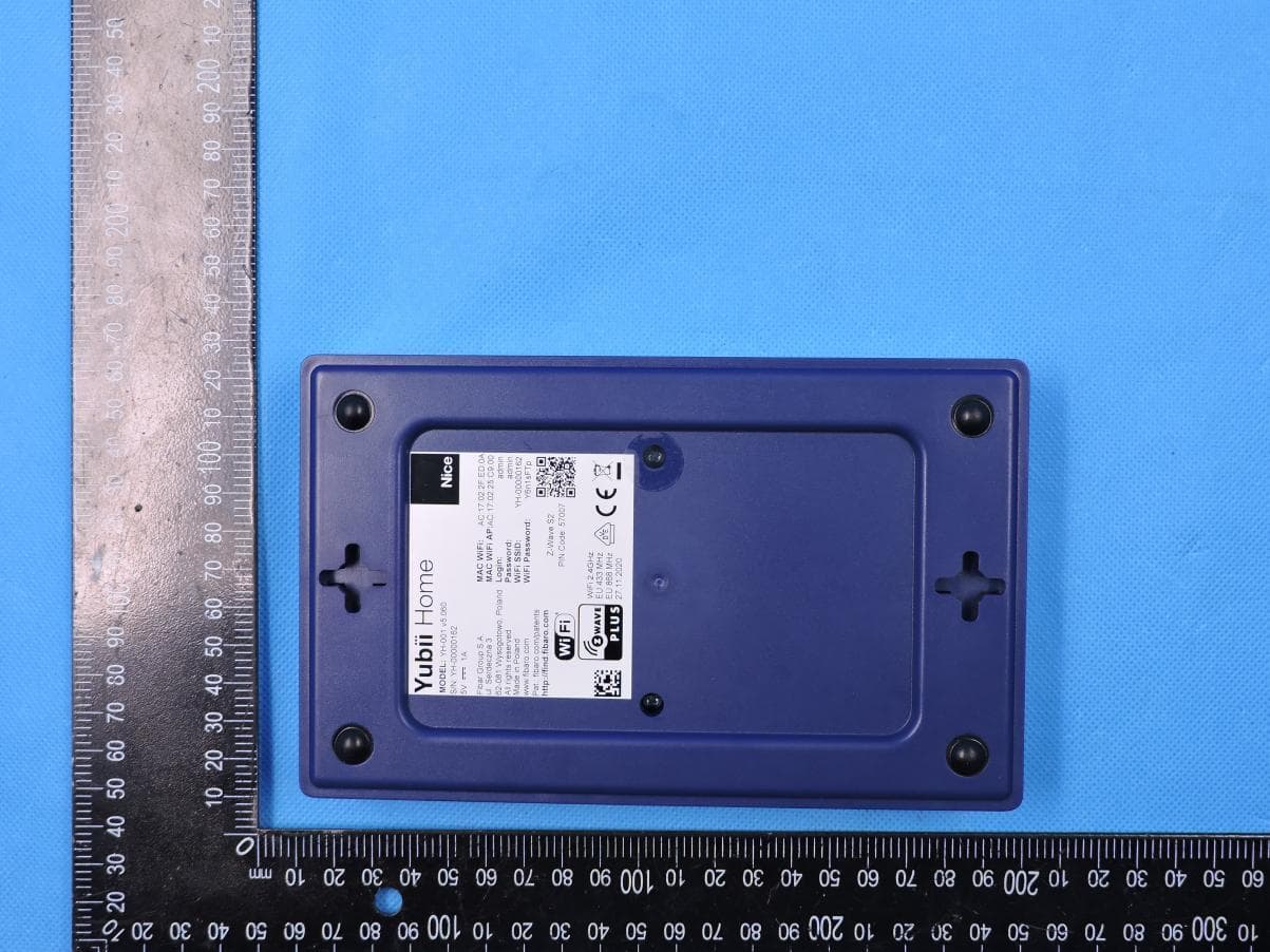
2AA9MYH001
Aug 10, 2021Yubii Home
Equipment Class
DSC - Part 15 Security/Remote Control Transmitter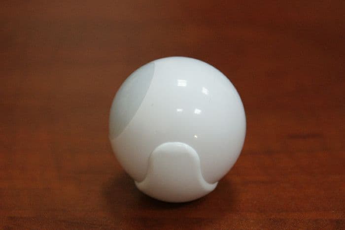
2AA9MFGMS002
May 03, 2015Motion Sensor
Equipment Class
DXX - Part 15 Low Power Communication Device Transmitter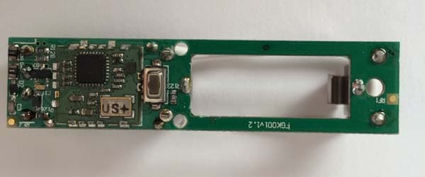
2AA9MFGK10X
Jan 19, 2014Door/Window Sensor
Equipment Class
DXT - Part 15 Low Power Transceiver, Rx Verified
2AA9MFGRGBWM441
Jan 16, 2014RGBW Controller
Equipment Class
DXT - Part 15 Low Power Transceiver, Rx Verified
2AA9MHC2
Dec 29, 2013Home Center
Equipment Class
DXT - Part 15 Low Power Transceiver, Rx Verified