2AA9MFGK10XDoor/Window Sensor
Fibar Group S.A.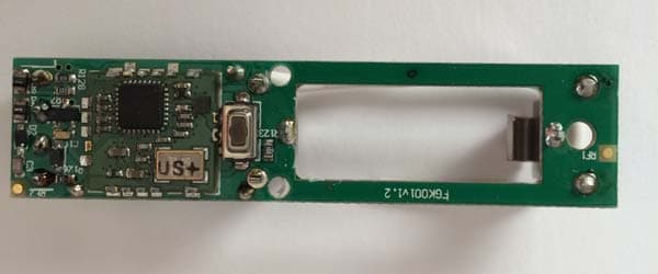
Click to zoom
Application Details
- Equipment Class
- DXT - Part 15 Low Power Transceiver, Rx Verified
- Date of Grant
- Jan 19, 2014
- Application Purpose
- Original Equipment
- Date of Application
- Jan 19, 2014
- Equipment Note
- Door/Window Sensor
- Frequency Range
- 908.40000000 - 908.40000000
- Company
- Fibar Group S.A.
- Country
- Poland
Documents & Files
Document Text
Text extracted from the exhibit documents filed with the FCC. Open a document above to read the original.
Users Manual
USA OPERATING MANUAL DOOR / WINDOW SENSOR FGK - 101 - 107 v2.1 - v2.3 The Fibaro Door / Window Sensor is a wireless, battery powered, Z-Wave compatible reed sensor. Each time its two parts, i.e. the sensor's body and a magnet separate, a radio signal is sent. In addition the Fibaro Door / Window Sensor supports one DS18B20 temperature sensor and has one potential free input. The Fibaro Door / Window Sensor is designed for use with scenes in home automation systems, alarm and surveillance systems and everywhere else where information related to opening / closing of doors, windows, garage gates, etc. is needed. Technical data: Power supply Inputs In accordance with EU standards FCC ID Supported temperature sensors Operating temperature Radio protocol Radio frequency Range Dimensions (L x W x H) single ER14250 (1/2AA) 3,6V battery single, potential-free EMC 2004/108/EC R&TTE 199/5/WE 2AA9MFGK10X single, DS18B20 0 - 40 °C Z-Wave 868,4 MHz EU; 908,4 MHz US; 921,4 MHz AU/NZ; 869,2 MHz RU; up to 30m indoors, depending on building materials used and the building structure 76 x 17 x 19 mm Technical information: • Controlled via. Fibaro System components or any other Z-Wave compatible controller, • Door/window opening detected through Sensor's body and a magnet separation, • Quick installation - easily mounted on doors, windows, garage gates, roller blinds, using double sided adhesive tape or screws, • Compatible with DS18B20 temperature sensors, • When connecting DS18B20 use single wire lead, no longer than 30 meters. • May be connected to a switch via potential-free IN input. I General Information on the Fibaro System: HINT Connections should be made specifically according to the diagrams presented in this manual. Incorrect connections may be hazardous or lead to device damage. i Fibaro is a system that does not require any additional conductors; it is based on the Z-Wave technology. Fibaro offers a wide array of advantages in comparison to other, similar systems. In general, radio-based systems establish a direct connection between the receiver and the transmitter. The radio signal is attenuated by every obstacle along its path (in the household e.g. walls, furniture, etc). In the worst case the radio system ceases to function. The advantage of the Fibaro System is the fact that the devices act not only as a signal receiver and transmitter, but also as a signal repeater. If a direct radio link between the transmitter and the receiver cannot be established, the connection will be carried out with the use of other devices participating in communication. II Sensor Installation: 1.Connect Fibaro Door/Window Sensor according to the appropriate diagram (if necessary) 2. Place battery inside the Sensor's casing, 3. Include into the Z-Wave network. 4. Install Fibaro Door/Window Sensor observing diagram 4, EXPLANATION OF CONDUCTOR MARKINGS: TMP - Tamper button. Detects removal, tampering etc. Used also as a service button, to include/exclude the device to/from the Z-Wave network, IN - Potential-free input, TP – (TEMP_POWER) - Power out for DS18B20 temperature sensor, TD – (TEMP_DATA) - Signal terminal for DS18B20 temperature sensor, GND – (GROUND) - Ground terminal. GLOSSARY OF TERMS: • INCLUSION - the device sends out a Node Info frame, which makes it possible to add it to the Fibaro System (Home Center 2), • EXCLUSION - remove the device from the Fibaro System, • ASSOCIATION - controlling other devices included in the Fibaro System, • Multi Channel Association - controlling other multi-channel devices included in the Fibaro System 3. Controlling the Fibaro Door/Window Sensor with the Home Center 2 Controller The Door/Window Sensor is a multichannel device. This means that it is equipped with an independent input circuit and a 1-wire bus allowing it to be connected to a DS18B20 temperature sensor. As a result, each device is represented by an independent icon in the System. 2. Resetting the Fibaro Door/Window Sensor There is one way to reset the Fibaro Door/Window Sensor. The procedure cleans its EPROM memory, including the main controller and Z-Wave network data. To reset the Fibaro Door/Window Sensor please follow below instructions: 1) Take off the Sensor's cover and remove battery. Make sure the TMP button is intact. 2) Touch the Sensor's body with a magnet, 3) Insert the battery, 4) Remove the magnet from the Sensor's body, 5) Remove the battery 6) Re-install the battery, 7) Reset will be confirmed by double LED blink. III Fibaro Sensor Start-up 1.Installation of the Door/Window Sensor STEP 1 Install the device observing the Figure 4 for correct positioning of the Sensor and the magnet. Close the Sensor's casing. [Inclusion/Exclusion] of the Fibaro Door/Window Sensor [to/from] the Z-Wave network. STEP 2 The Fibaro module must be in range of the Home Center 2 controller, because the procedure of inclusion to the Fibaro System requires direct communication with the controller. STEP 3 Locate TMP button, which allows for proper inclusion of device. The Fibaro Door/Window Sensor has a one, potential-free IN input. IN input status may be modified through the Sensor itself or by sending GND signal to IN (diagram 3). If the Door/Window Sensor will be used only as a binary sensor, do not install the magnet. i USING IN INPUT: Diagram 1 - General Diagram 2 - Connection to DS18B20 sensor Diagram 3 - Example connection - momentary switch Fibaro is a bidirectional wireless system. This means the signal is not only sent to the receivers, but also the receivers send feedback confirming the reception of the signal. This also confirms the condition of receivers, which allows us to check whether or not a device has actually been switched on. The safety of transmission of the Fibaro System is comparable with a wire-linked bus system. Fibaro operates in the free band for data transmission. The frequency depends on the radio regulations in each individual country. Each Fibaro network has its own unique network identifi…
Text truncated - open the document above for the full version.
ID Label/Location Info
Fibaro Door/Window FCC Label Exhibit
ID Label/Location Info
Fibaro Door/Window Sensor Label Location
Test Report
NVLAP Lab code: 100414-0 FCC 47 CFR PART 15 SUBPART C CERTIFICATION TEST REPORT FOR Door Window Sensor MODEL NUMBER: FGK001 FCC ID: 2AA9MFGK10X REPORT NUMBER: 10044158B ISSUE DATE: December 18, 2013 Prepared for Fibar Group sp. z.o.o ul. Lotnicza 1 Poznań, Poland 60-453 Prepared by UL LLC 333 Pfingsten Rd. Northbrook, IL 60062 TEL: (847) 272-8800 REPORT NO: 10044158B DATE: December 18, 2013 FCC ID: 2AA9MFGK10X Page 2 of 24 UL LLC FORM NO: CCSUP4701G 333 Pfingsten Rd., Northbrook, IL 60062 TEL: (847) 272-8800 This report shall not be reproduced except in full, without the written approval of UL LLC. Revision History Rev. Issue Date Revisions Revised By -- 12/18/13 Initial Issue M.Ferrer REPORT NO: 10044158B DATE: December 18, 2013 FCC ID: 2AA9MFGK10X Page 3 of 24 UL LLC FORM NO: CCSUP4701G 333 Pfingsten Rd., Northbrook, IL 60062 TEL: (847) 272-8800 This report shall not be reproduced except in full, without the written approval of UL LLC. TABLE OF CONTENTS 1. ATTESTATION OF TEST RESULTS ............................................................................................. 4 2. TEST METHODOLOGY .................................................................................................................. 5 3. FACILITIES AND ACCREDITATION .......................................................................................... 5 4. CALIBRATION AND UNCERTAINTY .......................................................................................... 5 4.1. MEASURING INSTRUMENT CALIBRATION ............................................................................. 5 4.2. SAMPLE CALCULATION ............................................................................................................ 5 4.3. MEASUREMENT UNCERTAINTY ............................................................................................... 5 5.5. DESCRIPTION OF TEST SETUP ................................................................................................ 7 6. TEST AND MEASUREMENT EQUIPMENT ................................................................................ 9 7. TEST RESULTS ............................................................................................................................... 10 7.1.1. 99%, 20dB BANDWIDTH ................................................................................................. 10 7.2. RADIATED EMISSIONS............................................................................................................. 13 7.2.1. HARMONICS AND SPURIOUS EMISSIONS ABOVE 1GHz ....................................... 16 7.2.2. WORST-CASE BELOW 1 GHz ........................................................................................ 18 8. SETUP PHOTOS .............................................................................................................................. 20 REPORT NO: 10044158B DATE: December 18, 2013 FCC ID: 2AA9MFGK10X Page 4 of 24 UL LLC FORM NO: CCSUP4701G 333 Pfingsten Rd., Northbrook, IL 60062 TEL: (847) 272-8800 This report shall not be reproduced except in full, without the written approval of UL LLC. 1. ATTESTATION OF TEST RESULTS COMPANY NAME: Fibar Group sp. z.o.o Ul. Lotnicza 1 Poznan, Poland 60-453 EUT DESCRIPTION: Door Window Sensor MODEL: FGK001 SERIAL NUMBER: Prototype DATE TESTED: September 12, 2013 – December 4, 2013 APPLICABLE STANDARDS STANDARD TEST RESULTS CFR 47 Part 15 Subpart C Part 15.249 Pass UL Verification Services Inc. tested the above equipment in accordance with the requirements set forth in the above standards. All indications of Pass/Fail in this report are opinions expressed by UL Verification Services Inc. based on interpretations and/or observations of test results. Measurement Uncertainties were not taken into account and are published for informational purposes only. The test results show that the equipment tested is capable of demonstrating compliance with the requirements as documented in this report. Note: The results documented in this report apply only to the tested sample, under the conditions and modes of operation as described herein. This document may not be altered or revised in any way unless done so by UL Verification Services Inc. and all revisions are duly noted in the revisions section. Any alteration of this document not carried out byUL Verification Services Inc. will constitute fraud and shall nullify the document. This report must not be used by the client to claim product certification, approval, or endorsement by NVLAP, NIST, any agency of the Federal Government, or any agency of any government. Approved & Released For UL CCS By: Tested By: BART MUCHA MICHAEL FERRER WiSE STAFF ENGINEER WiSE Project Lead UL Verification Services Inc. UL Verification Services Inc. REPORT NO: 10044158B DATE: December 18, 2013 FCC ID: 2AA9MFGK10X Page 5 of 24 UL LLC FORM NO: CCSUP4701G 333 Pfingsten Rd., Northbrook, IL 60062 TEL: (847) 272-8800 This report shall not be reproduced except in full, without the written approval of UL LLC. 2. TEST METHODOLOGY The tests documented in this report were performed in accordance with ANSI C63.4-2003, FCC CFR 47 Part 15, RSS-GEN Issue 3, and RSS-210 Issue 8. 3. FACILITIES AND ACCREDITATION The test sites and measurement facilities used to collect data are located at 333 Pfingsten Road, Northbrook, IL 60062, USA. UL NBK is accredited by NVLAP, Laboratory Code 100414-0. 4. CALIBRATION AND UNCERTAINTY 4.1. MEASURING INSTRUMENT CALIBRATION The measuring equipment utilized to perform the tests documented in this report has been calibrated in accordance with the manufacturer's recommendations, and is traceable to recognized national standards. 4.2. SAMPLE CALCULATION Where relevant, the following sample calculation is provided: Field Strength (dBuV/m) = Measured Voltage (dBuV) + Antenna Factor (dB/m) + Cable Loss (dB) – Preamp Gain (dB) 36.5 dBuV + 18.7 dB/m + 0.6 dB – 26.9 dB = 28.9 dBuV/m 4.3. MEASUREMENT UNCERTAINTY Where relevant, the follo…
Text truncated - open the document above for the full version.
Test Setup Photos
REPORT NO: 10044158B DATE: December 18, 2013 FCC ID: 2AA9MFGK10X Page 20 of 24 UL LLC FORM NO: CCSUP4701G 333 Pfingsten Rd., Northbrook, IL 60062 TEL: (847) 272-8800 This report shall not be reproduced except in full, without the written approval of UL LLC. 8. SETUP PHOTOS RADIATED RF MEASUREMENT SETUP (BELOW 1 GHz) RADIATED FRONT PHOTO (BELOW 1 GHz) Test Example shown for Spurious Emissions REPORT NO: 10044158B DATE: December 18, 2013 FCC ID: 2AA9MFGK10X Page 21 of 24 UL LLC FORM NO: CCSUP4701G 333 Pfingsten Rd., Northbrook, IL 60062 TEL: (847) 272-8800 This report shall not be reproduced except in full, without the written approval of UL LLC. RADIATED RF MEASUREMENT SETUP (ABOVE 1 GHz) RADIATED FRONT PHOTO (ABOVE 1 GHz) Test Example setup shown REPORT NO: 10044158B DATE: December 18, 2013 FCC ID: 2AA9MFGK10X Page 22 of 24 UL LLC FORM NO: CCSUP4701G 333 Pfingsten Rd., Northbrook, IL 60062 TEL: (847) 272-8800 This report shall not be reproduced except in full, without the written approval of UL LLC. RADIATED RF MEASUREMENT SETUP FOR PORTABLE CONFIGURATION X-AXIS FRONT PHOTO REPORT NO: 10044158B DATE: December 18, 2013 FCC ID: 2AA9MFGK10X Page 23 of 24 UL LLC FORM NO: CCSUP4701G 333 Pfingsten Rd., Northbrook, IL 60062 TEL: (847) 272-8800 This report shall not be reproduced except in full, without the written approval of UL LLC. Y-AXIS FRONT PHOTO REPORT NO: 10044158B DATE: December 18, 2013 FCC ID: 2AA9MFGK10X Page 24 of 24 UL LLC FORM NO: CCSUP4701G 333 Pfingsten Rd., Northbrook, IL 60062 TEL: (847) 272-8800 This report shall not be reproduced except in full, without the written approval of UL LLC. END OF REPORT Z-AXIS FRONT PHOTO
Contact Information
Applicant
Adam Pudlowski
Test Firm
UL LLCRick Titus
Technical Specifications
| # | Rule Parts | Frequency Range | Power Output |
|---|---|---|---|
| 1 | 15C | 908.4 MHz - 908.4 MHz | - |
Other Applications from Fibar Group S.A.
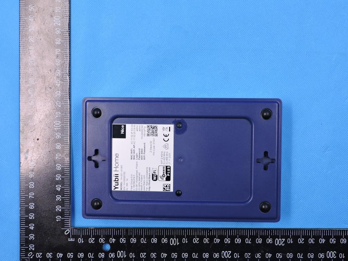
2AA9MYH001
Aug 10, 2021Yubii Home
Equipment Class
DSC - Part 15 Security/Remote Control Transmitter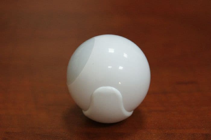
2AA9MFGMS002
May 03, 2015Motion Sensor
Equipment Class
DXX - Part 15 Low Power Communication Device Transmitter
2AA9MFGRGBWM441
Jan 16, 2014RGBW Controller
Equipment Class
DXT - Part 15 Low Power Transceiver, Rx Verified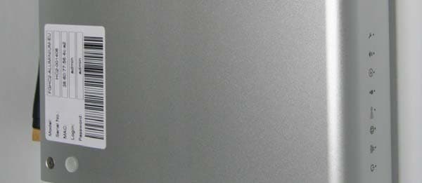
2AA9MHC2
Dec 29, 2013Home Center
Equipment Class
DXT - Part 15 Low Power Transceiver, Rx Verified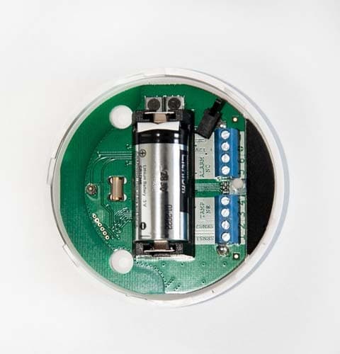
2AA9MFGFS101
Dec 16, 2013Flood Sensor
Equipment Class
DXT - Part 15 Low Power Transceiver, Rx Verified