2AA9MFGMS002Motion Sensor
Fibar Group S.A.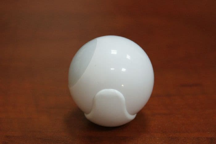
Click to zoom
Application Details
- Equipment Class
- DXX - Part 15 Low Power Communication Device Transmitter
- Date of Grant
- May 03, 2015
- Application Purpose
- Original Equipment
- Date of Application
- May 03, 2015
- Equipment Note
- Motion Sensor
- Frequency Range
- 908.40000000 - 916.00000000
- Company
- Fibar Group S.A.
- Country
- Poland
Documents & Files
Document Text
Text extracted from the exhibit documents filed with the FCC. Open a document above to read the original.
Users Manual
USA Diagram 4 - Fibaro Motion Sensor installation. Diagram 3 - preparing Fibaro Motion Sensor for operation. TECHNICAL INFORMATION VI. INSTALLATION NOTES X. EARTHQUAKE DETECTOR MODE V. DETECTION AREA AND WORKING CONDITIONS VII. RESETTING THE FIBARO MOTION SENSOR XI. SENSOR’S ORIENTATION IN SPACE XII. LED VISUAL INDICATIONS AND SETTINGS XIII. Z-WAVE RANGE TEST VIII. OPERATING WITHIN THE Z-WAVE NETWORK IX. ASSOCIATIONS Power Supply: EU directives compliance: Recommended installation height: Operational Temperature: Measured Temperature Range: Temperature Measuring Accuracy: Light Intensity Measuring Range: Radio Protocol: Radio Frequency: Range: CR123A battery, 3.0V DC RoHS 2011/65/EU LVD 2006/95/EC EMC 2004/108/EC R&TTE 1999/5/EC 2,4m 0-40 o C -20 to 100 o C 0,5 o C (within 0 o C-40 o C range) 0-32000 LUX Z-Wave 868,4 or 869,8 MHz EU; 908,4 or 916 MHz US; 921,4 or 919,8 MHz ANZ; 869 MHz RU; up to 50 m outdoors up to 30 m indoors (depending on terrain and building structure) Diagram 6 - Fibaro Motion Sensor’s motion detection area. Diagram 5 - Fibaro Motion Sensor’s proximity area. I’M READY SPECIFICATIONS The Fibaro Motion Sensor can be included into the Z-Wave network by using the B-button. 1) Open the sensor’s casing by turning the cover counter-clockwise. Enclosure lock is marked with a dot. 2) Unlock battery by removing “I'm ready” stripe. 3) Make sure the device is located within the direct range of the main controller. 4) Set the main controller into learning mode (see main controller’s operating manual). 5) Quickly, triple click the B-button - LED diode will glow blue to confirm setting into learning mode. 6) Fibaro Motion Sensor will be detected and included into the Z-Wave network. Wait for the main controller to configure the sensor. 7) If necessary, wake up the Motion Sensor by clicking the B-button. 8) Close the sensor’s casing and install the device in desired place. Diagram 1 - B-button. Diagram 2 - Motion detector, light sensor, LED diode. III. EXCLUDING SENSOR FROM THE Z-WAVE NETWORK IV. SENSOR INSTALLATION II. Z-WAVE NETWORK INCLUSION B-BUTTON SENSOR 1) Make sure tampering the device will not result in undesirable effects. Dismounting the sensor can trigger an alarm. 2) Open the sensor’s casing by turning the cover counter-clockwise. Enclosure lock is marked with a dot. 3) Make sure the sensor's battery is unlocked. 4) Set the main controller into learning mode (see main controller’s operating manual). 5) Quickly, triple click the B-button, located inside Fibaro Motion Sensor’s casing. LED diode will glow blue confirming that the device has sent the Node Info Z-Wave command frame. 1) Include the device into the Z-Wave network (see p.II). Note that the inclusion process may be performed ONLY in direct range of the main controller. 2) Install the sensor’s holder in desired location. 3) Insert the Motion Sensor in its holder. 4) Test the sensor’s operation - check whether the LED diode indicates motion detection. 5) Test the Z-Wave network assuring the device is within range. OPERATING MANUAL FIBARO MOTION SENSOR FGMS-001-USA-A-V1.02 The Fibaro Motion Sensor is a universal Z-Wave multi-sensor. Along with detecting motion the device measures the temperature and light intensity. The sensor has a built-in accelerometer to detect any tampering of the device. The Fibaro Motion Sensor is battery powe- red device and designed to be installed quickly and easily on any surface. The LED indicator signals motion, temperature level, opera- ting mode and can be used to see if device is within the Z-Wave network. The motion sensor can be used for lighting scenes and presence monitoring systems. I. GLOSSARY OF TERMS • adding - Z-Wave device learning mode, allowing to add the device to existing Z-Wave network. • removing - Z-Wave device learning mode, allowing to remove the device from existing Z-Wave network. • association (linking devices) - direct control of other devices within the Z-Wave network system. • multi-channel association - controlling other multi-channel devices within the Z-Wave network. • control command - type of Z-Wave network command enforcing change of device state. • report command - type of Z-Wave network command holding an additional information, e.g. alarm state or measured temperature. • alarm command - type of Z-Wave network command holding a warning of danger occurrence, e.g. fire alarm. • multi-channel device - device having multiple endpoints - various device functions. NOTE The Fibaro Motion Sensor is a Security Enabled Z-Wave Plus product and a Security Enabled Z-Wave Controller must be used in order to fully utilize the product. i - Compatible with any Z-Wave+ controller. - Works with other Z-Wave network devices, but as a battery device it doesn’t take part in signal routing. - Supports protected mode (Z-Wave network security mode) with AES-128 encryption. - Detects motion using a passive IR sensor. - Measures the temperature. - Measures the light intensity. - Easy installation on a wall or any surface. - Protected against tampering and theft - once vibrations are detected, the notification is sent to the main controller. - Alarms of movement and temperature are signaled by LED diode blinking. - Simple earthquake detector mode. Fibaro Motion Sensor cannot be pointed at any source of heat (e.g. radiators, fireplaces, cookers, etc.) or at any source of light (direct sunlight, lamps). It’s not recommended to install the Motion Sensor in places prone to drafts and rooms with rapid fluctuations in air temperature. Sensor can be mounted using the included screw or the sticker. Fibaro Motion Sensor allows for association of five groups: 1st Association Group „Lifeline” is a reporting group, assigned to the device status. Main Z-Wave+ network controller should be added to this group. The „Lifeline” group can handle only one device. If Fibaro Motion Sensor operates in protected mode, outgoing messages are always encrypted. 2nd Association Group „Motion” is assigned …
Text truncated - open the document above for the full version.
ID Label/Location Info
ITE CMIIT ID: 2015DJ0096 FCC ID: 2AA9MFGMS002
Test Report
NVLAP Lab code: 100414-0 FCC 47 CFR PART 15 SUBPART C INDUSTRY CANADA RSS-210 ISSUE 8 CERTIFICATION TEST REPORT FOR Motion Sensor MODEL NUMBER: FGMS-001 FCC ID: 2AA9MFGMS002 REPORT NUMBER: 10340736A ISSUE DATE: December 29, 2014 Prepared for Fibar Group sp. z.o.o Ul. Lotnicza 1 Poznań, Poland 60-453 Prepared by UL LLC 333 Pfingsten Rd. Northbrook, IL 60062 TEL: (847) 272-8800 REPORT NO: 10340736A DATE: December 29, 2014 FCC ID: 2AA9MFGMS002 MODEL NUMBER: FGMS-001 Page 2 of 30 UL LLC FORM NO: CCSUP4701i 333 Pfingsten Rd., Northbrook, IL 60062, USA TEL: (847) 272-8800 This report shall not be reproduced except in full, without the written approval of UL LLC Revision History Rev. Issue Date Revisions Revised By -- 12/29/14 Initial Issue M.Ferrer REPORT NO: 10340736A DATE: December 29, 2014 FCC ID: 2AA9MFGMS002 MODEL NUMBER: FGMS-001 Page 3 of 30 UL LLC FORM NO: CCSUP4701i 333 Pfingsten Rd., Northbrook, IL 60062, USA TEL: (847) 272-8800 This report shall not be reproduced except in full, without the written approval of UL LLC TABLE OF CONTENTS 1. ATTESTATION OF TEST RESULTS ............................................................................................. 4 2. TEST METHODOLOGY .................................................................................................................. 5 3. FACILITIES AND ACCREDITATION .......................................................................................... 5 4. CALIBRATION AND UNCERTAINTY .......................................................................................... 5 4.1. MEASURING INSTRUMENT CALIBRATION ............................................................................. 5 4.2. SAMPLE CALCULATION ............................................................................................................ 5 4.3. MEASUREMENT UNCERTAINTY ............................................................................................... 6 5.5. DESCRIPTION OF TEST SETUP ................................................................................................ 8 6. TEST AND MEASUREMENT EQUIPMENT .............................................................................. 10 7. TEST RESULTS ............................................................................................................................... 11 7.1.1. 99% BANDWIDTH and 20dB Bandwidth ......................................................................... 11 7.2. RADIATED EMISSIONS............................................................................................................. 15 7.2.1. FUNDAMENTAL FREQUENCY RADIATED EMISSION ............................................ 16 7.2.2. HARMONICS AND SPURIOUS EMISSIONS ABOVE 1GHz ....................................... 17 7.2.3. WORST-CASE BELOW 1 GHz ........................................................................................ 23 8. SETUP PHOTOS .............................................................................................................................. 26 REPORT NO: 10340736A DATE: December 29, 2014 FCC ID: 2AA9MFGMS002 MODEL NUMBER: FGMS-001 Page 4 of 30 UL LLC FORM NO: CCSUP4701i 333 Pfingsten Rd., Northbrook, IL 60062, USA TEL: (847) 272-8800 This report shall not be reproduced except in full, without the written approval of UL LLC 1. ATTESTATION OF TEST RESULTS COMPANY NAME: Fibar Group sp. z.o.o Ul. Lotnicza 1 Poznan, Poland 60-453 EUT DESCRIPTION: Motion Sensor MODEL: FGMS-001 SERIAL NUMBER: Prototype DATE TESTED: November 25, 2014 – December 18, 2014 APPLICABLE STANDARDS STANDARD TEST RESULTS CFR 47 Part 15 Subpart C Pass INDUSTRY CANADA RSS-210 Issue 8 Annex 8 Pass INDUSTRY CANADA RSS-GEN Issue 4 Pass UL LLC tested the above equipment in accordance with the requirements set forth in the above standards. All indications of Pass/Fail in this report are opinions expressed by UL LLC based on interpretations and/or observations of test results. Measurement Uncertainties were not taken into account and are published for informational purposes only. The test results show that the equipment tested is capable of demonstrating compliance with the requirements as documented in this report. Note: The results documented in this report apply only to the tested sample, under the conditions and modes of operation as described herein. This document may not be altered or revised in any way unless done so by UL LLC and all revisions are duly noted in the revisions section. Any alteration of this document not carried out by UL LLC will constitute fraud and shall nullify the document. This report must not be used by the client to claim product certification, approval, or endorsement by NVLAP, NIST, any agency of the Federal Government, or any agency of any government. Approved & Released For UL CCS By: Tested By: BART MUCHA MICHAEL FERRER WiSE STAFF ENGINEER WiSE Program Manager UL Verification Services Inc. UL Verification Services Inc. REPORT NO: 10340736A DATE: December 29, 2014 FCC ID: 2AA9MFGMS002 MODEL NUMBER: FGMS-001 Page 5 of 30 UL LLC FORM NO: CCSUP4701i 333 Pfingsten Rd., Northbrook, IL 60062, USA TEL: (847) 272-8800 This report shall not be reproduced except in full, without the written approval of UL LLC 2. TEST METHODOLOGY The tests documented in this report were performed in accordance with ANSI C63.4-2003, FCC CFR 47 Part 2, FCC CFR 47 Part 15, RSS-GEN Issue 4, and RSS-210 Issue 8. 3. FACILITIES AND ACCREDITATION The test sites and measurement facilities used to collect data are located at 333 Pfingsten Road, Northbrook, IL 60062 USA. UL NBK is accredited by NVLAP, Laboratory Code 100414-0. The full scope of accreditation can be viewed at http://ts.nist.gov/Standards/scopes/1004140.htm 4. CALIBRATION AND UNCERTAINTY 4.1. MEASURING INSTRUMENT CALIBRATION The measuring equipment utilized to perform the tests documented in this report has been calibrated in accordance with the manufacturer's recommendations, and is traceable to recognized nationa…
Text truncated - open the document above for the full version.
Test Setup Photos
REPORT NO: 10340736A DATE: December 29, 2014 FCC ID: 2AA9MFGMS002 MODEL NUMBER: FGMS-001 Page 26 of 30 UL LLC FORM NO: CCSUP4701i 333 Pfingsten Rd., Northbrook, IL 60062, USA TEL: (847) 272-8800 This report shall not be reproduced except in full, without the written approval of UL LLC 8. SETUP PHOTOS ANTENNA PORT MEASUREMENT SETUP ANTENNA PORT PHOTO REPORT NO: 10340736A DATE: December 29, 2014 FCC ID: 2AA9MFGMS002 MODEL NUMBER: FGMS-001 Page 27 of 30 UL LLC FORM NO: CCSUP4701i 333 Pfingsten Rd., Northbrook, IL 60062, USA TEL: (847) 272-8800 This report shall not be reproduced except in full, without the written approval of UL LLC RADIATED RF MEASUREMENT SETUP FOR PORTABLE CONFIGURATION Below 1GHz Spurious REPORT NO: 10340736A DATE: December 29, 2014 FCC ID: 2AA9MFGMS002 MODEL NUMBER: FGMS-001 Page 28 of 30 UL LLC FORM NO: CCSUP4701i 333 Pfingsten Rd., Northbrook, IL 60062, USA TEL: (847) 272-8800 This report shall not be reproduced except in full, without the written approval of UL LLC Above 1GHz Spurious REPORT NO: 10340736A DATE: December 29, 2014 FCC ID: 2AA9MFGMS002 MODEL NUMBER: FGMS-001 Page 29 of 30 UL LLC FORM NO: CCSUP4701i 333 Pfingsten Rd., Northbrook, IL 60062, USA TEL: (847) 272-8800 This report shall not be reproduced except in full, without the written approval of UL LLC Z-AXIS FRONT PHOTO
Contact Information
Applicant
Adam Pudlowski
Test Firm
UL LLCRick Titus
Technical Specifications
| # | Rule Parts | Frequency Range | Power Output |
|---|---|---|---|
| 1 | 15C | 908.4 MHz - 916 MHz | - |
Other Applications from Fibar Group S.A.
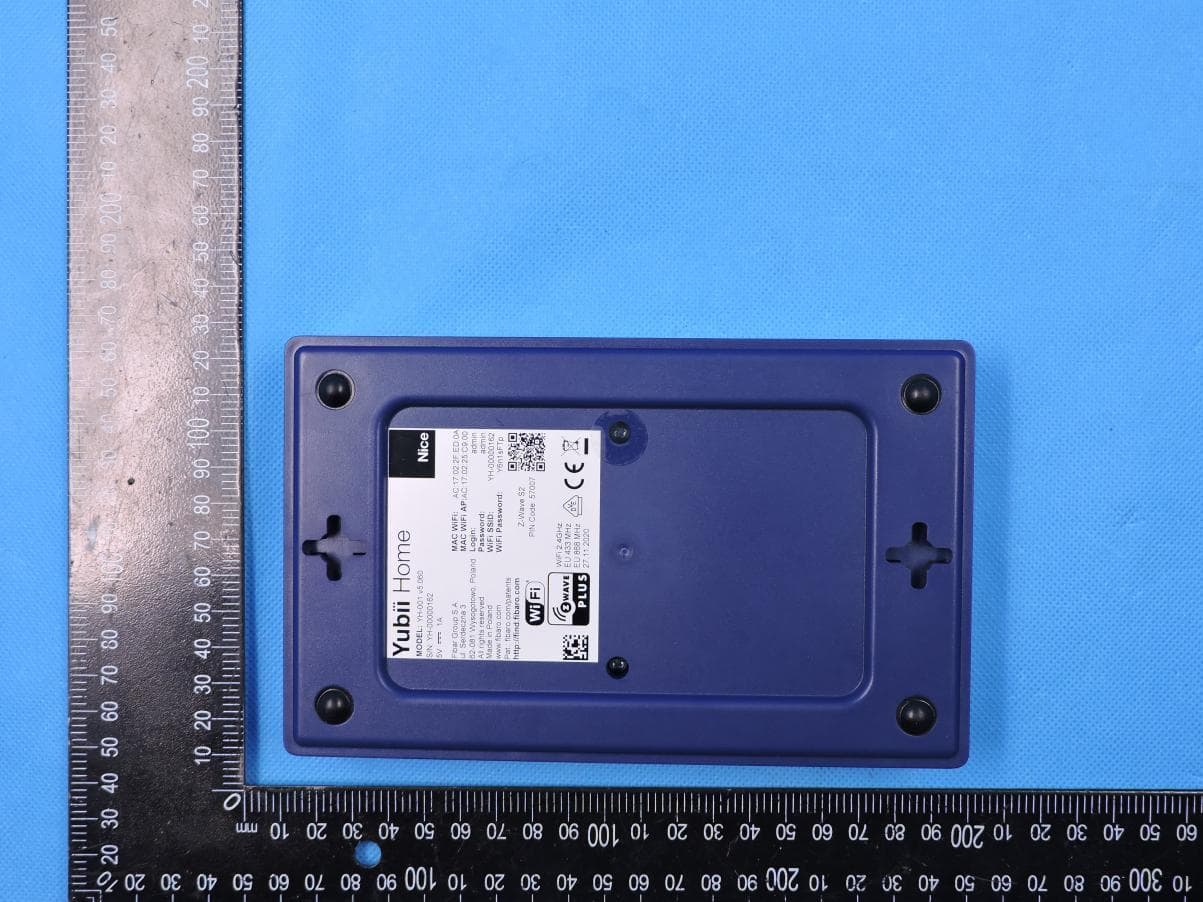
2AA9MYH001
Aug 10, 2021Yubii Home
Equipment Class
DSC - Part 15 Security/Remote Control Transmitter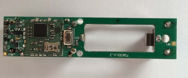
2AA9MFGK10X
Jan 19, 2014Door/Window Sensor
Equipment Class
DXT - Part 15 Low Power Transceiver, Rx Verified
2AA9MFGRGBWM441
Jan 16, 2014RGBW Controller
Equipment Class
DXT - Part 15 Low Power Transceiver, Rx Verified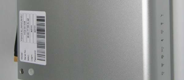
2AA9MHC2
Dec 29, 2013Home Center
Equipment Class
DXT - Part 15 Low Power Transceiver, Rx Verified
2AA9MFGFS101
Dec 16, 2013Flood Sensor
Equipment Class
DXT - Part 15 Low Power Transceiver, Rx Verified