2AAMXNEMA10DIMNEMA Controller, 120/277VAC 5A 0-10V
Ideal Industries, Inc.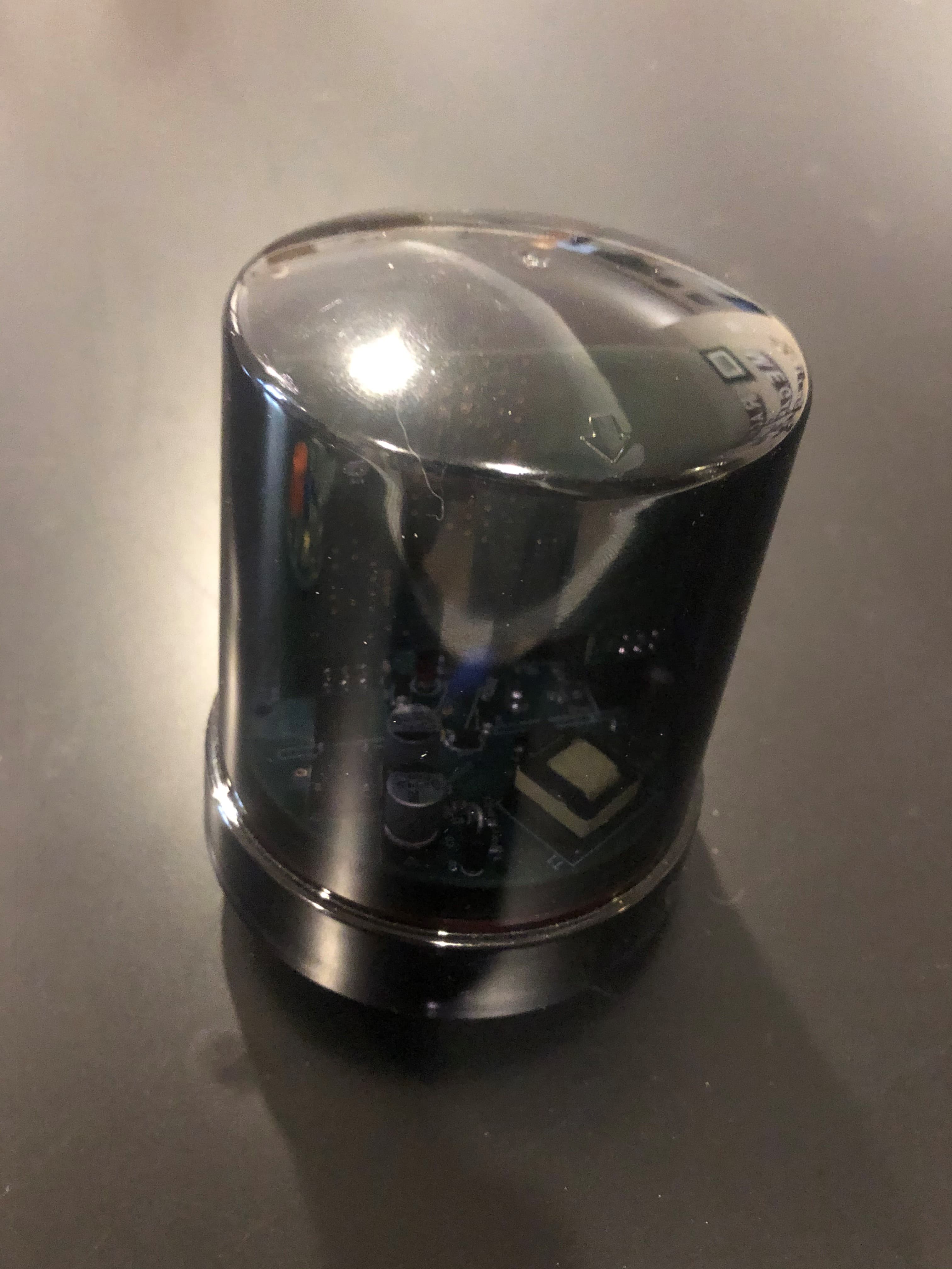
Click to zoom
Application Details
- Equipment Class
- DTS - Digital Transmission System
- Date of Grant
- Sep 24, 2020
- Application Purpose
- Original Equipment
- Date of Application
- Sep 24, 2020
- Equipment Note
- NEMA Controller, 120/277VAC 5A 0-10V
- Frequency Range
- 902.70000000 - 927.30000000
- Company
- Ideal Industries, Inc.
- Country
- United States
Documents & Files
Document Text
Text extracted from the exhibit documents filed with the FCC. Open a document above to read the original.
Users Manual
Product Manual NEMA10DIM – 7 Pin Outdoor Controller -10DIM Users Manual – NEMA10DIM – 7 Pin Outdoor Controller -10DIM Page 1 www.idealindustries.com PRODUCT DESCRIPTION The Audacy NEMA10DIM is an outdoor controller that is compliant with NEMA/ANSI C136.47 7-pin dimming support receptacle. The NEMA10DIM is a 110- 277VAC powered device specially designed to allow a user to control outdoor light fixtures via the Audacy wireless lighting control system. The NEMA10DIM can be networked with the Audacy System to provide scheduling control. It can also be controlled via an integrated photosensor. The NEMA10DIM also supports an optional external motion sensor. KEY FEATURES FCC and IC approved Flexible wall mounting options Small form factor with internal antenna RoHS compliant Factory configurable for custom applications PRODUCT CONTENTS The following items are included inside the package: Qty Description 1 NEMA10DIM Controller 1 Instruction card Audacy®, Smart Connector® are registered trademarks of IDEAL INDUSTRIES. All other trademarks are the property of their respective owners. Product Manual NEMA10DIM – 7 Pin Outdoor Controller -10DIM Users Manual – NEMA10DIM – 7 Pin Outdoor Controller -10DIM Page 2 www.idealindustries.com SET-UP AND OPERATION Installation is straight forward. The device is just plugged into a fixture with a compatible NEMA/ANSI C136.41 connector. Then configure the device on the Audacy Wireless system. SPECIFICATIONS Item Description Radio 915 MHz Internal Antenna Regulatory Approvals FCC Part 15 and Industry Canada Contains FCC ID: 2AAMXNEMA10DIM Contains IC: 11250A-NEMA10DIM UL916 Transmit Range 300 ft. indoors to an Audacy Gateway or Controller in a typical commercial office building. 1000ft+ distances with outdoor line of site. Power 110-277V AC Operating Temperature -40°C to 70°C Storage Temperature -40°C to 85°C Installation Environment Indoor/Outdoor use only Color Translucent Grey Dimensions 4.21”x3.3” Warranty 1 year Product Manual NEMA10DIM – 7 Pin Outdoor Controller -10DIM Users Manual – NEMA10DIM – 7 Pin Outdoor Controller -10DIM Page 3 www.idealindustries.com MECHANICAL VIEWS *Dimensions in inches Product Manual NEMA10DIM – 7 Pin Outdoor Controller -10DIM Users Manual – NEMA10DIM – 7 Pin Outdoor Controller -10DIM Page 4 www.idealindustries.com SUPPORT Technical support for IDEAL INDUSTRIES products can be initiated through the following methods: Website: http://www.idealindustries.com/support/ Telephone: +1 800-435-0705 Email: [email protected] Product Manual NEMA10DIM – 7 Pin Outdoor Controller -10DIM Users Manual – NEMA10DIM – 7 Pin Outdoor Controller -10DIM Page 5 www.idealindustries.com COMPLIANCE STATEMENTS This device is intended for commercial and industrial applications. Changes or modifications not expressly approved by IDEAL could void the user’s authority to operate the equipment. Use and maintain device only as specified in this manual. This equipment has been tested and found to comply with the limits for a Class B digital device, pursuant to Part 15 of the FCC Rules. These limits are designed to provide reasonable protection against harmful interference in a residential installation. This equipment generates, uses, and can radiate radio frequency energy and, if not installed and used in accordance with the instructions, may cause harmful interference to radio communications. However, there is no guarantee that interference will not occur in a particular installation. If this equipment does cause harmful interference to radio or television reception, which can be determined by turning the equipment off and on, the user is encouraged to try to correct the interference by one of the following measures: -- Reorient or relocate the receiving antenna. -- Increase the separation between the equipment and receiver. -- Connect the equipment into an outlet on a circuit different from that to which the receiver is connected. -- Consult the dealer or an experienced radio/TV technician for help. WARNING! FCC and IC Radiation Exposure Statement: This equipment complies with FCC’s and IC’s RF radiation exposure limits set forth for an uncontrolled environment under the following conditions: 1. This equipment should be installed and operated such that a minimum separation distance of 20cm is maintained between the radiator (antenna) & user’s/nearby person’s body at all times. 2. This transmitter must not be co-located or operating in conjunction with any other antenna or transmitter. This device complied with Industry Canada licence-exempt RSS standard(s) and part 15 of the FCC Rules. Operation is subject to the following two conditions: (1) this device may not cause interference, and (2) this device must accept any interference, including interference that may cause undesired operation of the device. Ce dispositif conformé à Industrie Canada exempts de licence standard RSS (s) et la partie 15 des règles de la FCC. Son fonctionnement est soumis aux deux conditions suivantes: (1) cet appareil ne peut pas provoquer d'interférences, et (2) ce dispositif doit accepter toute interférence, y compris les interférences qui peuvent entraîner un mauvais fonctionnement de l'appareil. Product Manual NEMA10DIM – 7 Pin Outdoor Controller -10DIM Users Manual – NEMA10DIM – 7 Pin Outdoor Controller -10DIM Page 6 www.idealindustries.com IMPORTANT NOTICE Information furnished by IDEAL INDUSTRIES, INC. is believed to be accurate and reliable. No license, express or implied, to any intellectual property rights is granted by this document. No responsibility is assumed by IDEAL INDUSTRIES, INC. for its use, nor for any infringements of patents or other rights of third parties that may result from its use. IDEAL INDUSTRIES, INC. assumes no liability for misuse of this product. Specifications are subject to change without notice. No license is granted by implication or otherwise under any patent or patent rights of IDEAL INDUSTRIES, INC. Trademarks and registered trademarks …
Text truncated - open the document above for the full version.
Attestation Statements
IDEAL INDUSTRIES, INC. Becker Place • Sycamore, Illinois 60178 • 815.895.5181 • www.idealindustries.com Agent’s Authorization Letter October 10, 2019 I, the Grantee Contact of Record for IDEAL INDUSTRIES, INC., do hereby authorize, until further notice, Elite Electronic Engineering, Inc., 1516 Centre Circle, Downers Grove, IL 60615, to act on our behalf in dealings before the Federal Communications Commission with respect to all matters relating to equipment authorizations under 47 CFR. This authorization includes, but is not limited to, the signing of Form 731. I certify that no party (as defined in 47 CFR 1.2002) to this application, including myself, is subject to a denial of federal benefits, that include FCC benefits, pursuant to section 5301 of the Anti-Drug Abuse Act of 1988, 21 U.S.C., 853A. Certified By: ____________________________ Tim Tunnell Sr. Electrical Engineer IDEAL INDUSTRIES, INC. Becker Place Sycamore, IL 60178 815.899.7774 www.idealindustries.com
Cover Letter(s)
IDEAL INDUSTRIES, INC. Becker Place • Sycamore, Illinois 60178 • 815.895.5181 • www.idealindustries.com July 22nd, 2020 To: Federal Communications Commission 7435 Oakland Mills Road Columbia, MD 21046-1609 Elite Electronic Engineering, Inc. 1516 Center Circle Downers Grove, IL 60515 Re: Confidentiality Request Gentlemen: This letter is to comply with 47 CFR 0.457(d)(2) pertaining to confidential material. IDEAL INDUSTRIES, INC. requests that the following documents regarding this submission for FCC ID 2AAMXNEMA10DIM be kept confidential. 1. Schematics 2. Block diagram 3. Circuit/Technical Description The material above contains technical data, which would customarily be guarded from competitors. Sincerely, Tim Tunnell Sr. Electrical Engineer IDEAL INDUSTRIES, INC. Becker Place Sycamore, IL 60178 815.895.1295 www.idealindustries.com
Test Report
For Ideal Industries Inc. 1375 Park Avenue Sycamore, IL 60178 P.O. Number AWS1091 Date Received July 16, 2020 Date Tested July 16 - 21, 2020 Test Personnel Tylar Jozefczyk Specification FCC "Code of Federal Regulations" Title 47, Part 15, Subpart C, Sections 15.207 and 15.247 for Digital Modulation Intentional Radiators Operating within the band 902-928MHz, 2400-2483.5MHz, 5725-5850MHz FCC “Code of Federal Regulations” Title 47, Part 15, Subpart 15B, Section 15.107 and 15.109 for Receivers Industry Canada RSS-247 Industry Canada RSS-GEN Test Report By: Tylar Jozefczyk EMC Engineer Requested By: Tim Tunnell Ideal Industries Inc. Approved By: Raymond J. Klouda Registered Professional Engineer of Illinois - 44894 Engineering Test Report No. 2003293-01 Measurement of RF Interference from a NEMA10DIM 7 Pin Outdoor Controller Transceiver Engineering Test Report No. 2003293-01 THIS REPORT SHALL NOT BE REPRODUCED, EXCEPT IN FULL, WITHOUT THE WRITTEN APPROVAL OF ELITE ELECTRONIC ENGINEERING INCORPORATED. Page 2 of 93 TABLE OF CONTENTS PARAGRAPH DESCRIPTION OF CONTENTS PAGE NO. 1. INTRODUCTION ............................................................................................................................................... 5 1.1 Scope of Tests .......................................................................................................................................... 5 1.2 Purpose ..................................................................................................................................................... 5 1.3 Deviations, Additions and Exclusions ....................................................................................................... 5 1.4 EMC Laboratory Identification .................................................................................................................. 5 1.5 Laboratory Conditions ............................................................................................................................... 5 2. APPLICABLE DOCUMENTS ............................................................................................................................ 5 3. EUT SET-UP AND OPERATION ...................................................................................................................... 6 3.1 General Description .................................................................................................................................. 6 3.1.1 Power Input .......................................................................................................................................... 6 3.1.2 Peripheral Equipment ........................................................................................................................... 6 3.1.3 Interconnect Cables ............................................................................................................................. 6 3.1.4 Grounding ............................................................................................................................................. 6 3.2 Software .................................................................................................................................................... 6 3.3 Operational Mode ..................................................................................................................................... 6 3.4 EUT Modifications ..................................................................................................................................... 6 4. TEST FACILITY AND TEST INSTRUMENTATION .......................................................................................... 6 4.1 Shielded Enclosure ................................................................................................................................... 6 4.2 Test Instrumentation ................................................................................................................................. 7 4.3 Calibration Traceability ............................................................................................................................. 7 4.4 Measurement Uncertainty ......................................................................................................................... 7 5. TEST PROCEDURES ....................................................................................................................................... 7 5.1 Receiver .................................................................................................................................................... 7 5.1.1 Powerline Conducted Emissions .......................................................................................................... 7 5.1.1.1 Requirements .............................................................................................................................. 7 5.1.1.2 Procedures .................................................................................................................................. 7 5.1.1.3 Results ......................................................................................................................................... 8 5.1.2 Radiated Measurements ...................................................................................................................... 8 5.1.2.1 Requirements .............................................................................................................................. 8 5.1.2.2 Procedures .................................................................................................................................. 8 5.1.2.1 Results ......................................................................................................................................... 9 5.2 Transmitter ............................................................................................................…
Text truncated - open the document above for the full version.
Test Setup Photos
Test Item Setup Test Setup for Conducted Emissions Test Setup for Radiated Emissions – 30MHz to 1GHz, Horizontal Polarization Test Setup for Radiated Emissions – 30MHz to 1GHz, Vertical Polarization Test Setup for Radiated Emissions (Receiver) – 1 to 10GHz, Horizontal Polarization Test Setup for Radiated Emissions (Receiver) – 1 to 10GHz, Vertical Polarization Test Setup for Radiated Emissions (Transmitter) – 1 to 10GHz, Horizontal Polarization Test Setup for Radiated Emissions (Transmitter) – 1 to 10GHz, Vertical Polarization
Contact Information
Applicant
Tim Tunnell(Sr. Electrical Engineer)
Technical Contact
IDEAL Industries, Inc.Tim Tunnell
[email protected]815 895 1295
1375 Park Avenue · Sycamore · United States
Non-Technical Contact
IDEAL Industries, Inc.Tim Tunnell
[email protected]815 895 1295
Test Firm
Elite Electronic Engineering Inc.Kevin Halpin
Technical Specifications
| # | Rule Parts | Frequency Range | Power Output |
|---|---|---|---|
| 1 | 15C | 902.7 MHz - 927.3 MHz | 100.00 mW |
Other Applications from Ideal Industries, Inc.
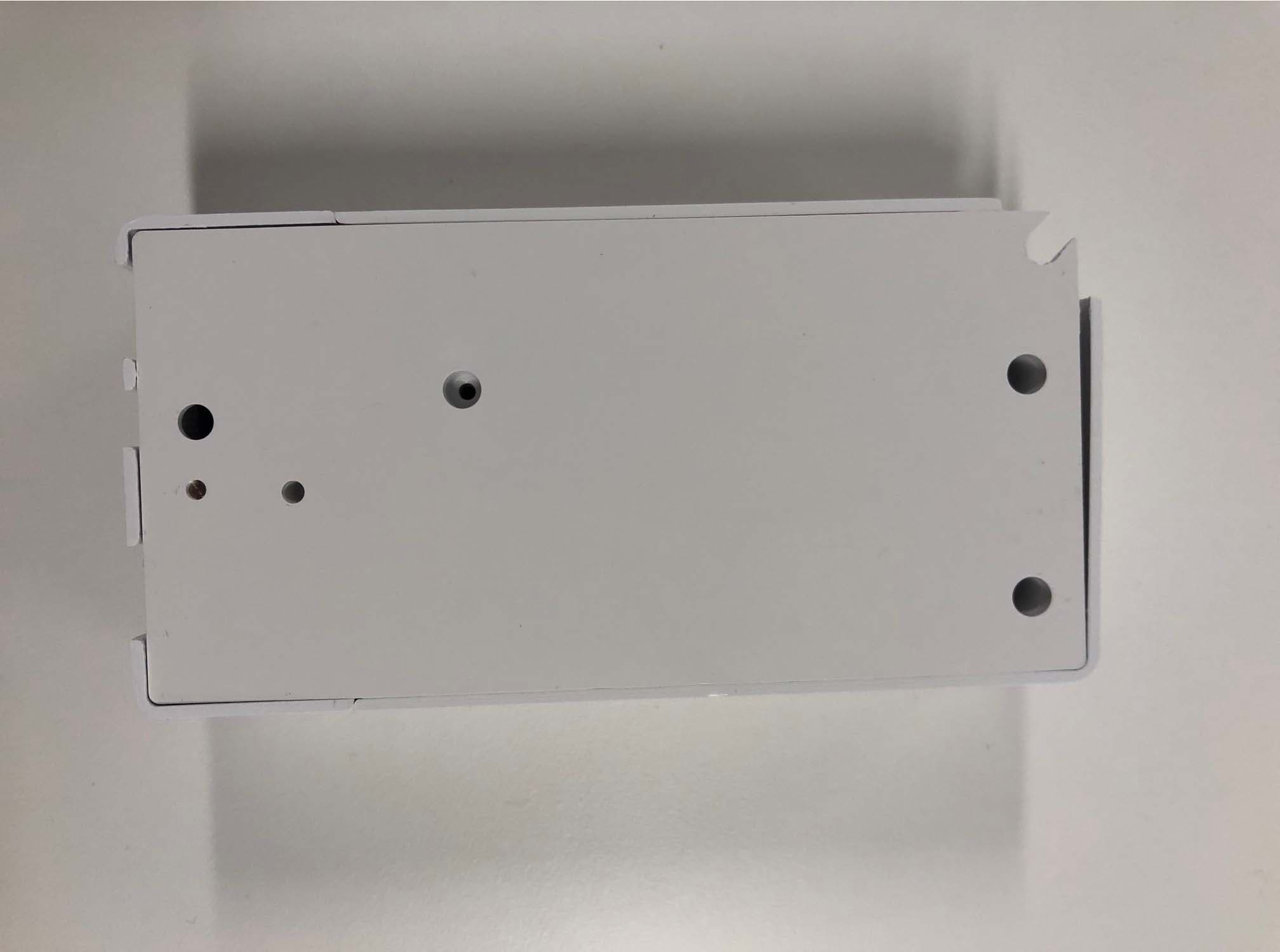
2AAMXIBRIDGE
Mar 12, 20204 Port Contact Closure Toggle Switch
Equipment Class
DTS - Digital Transmission System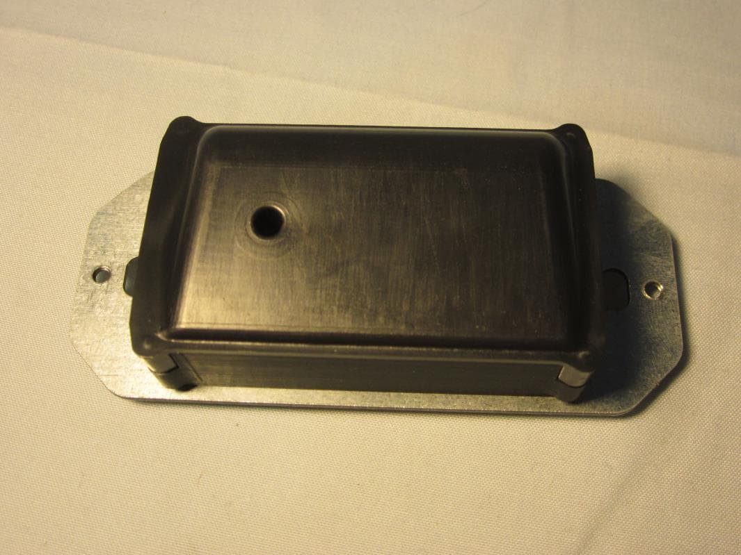
2AAMXWMS1200
Jan 27, 2016Smart Switch
Equipment Class
DTS - Digital Transmission System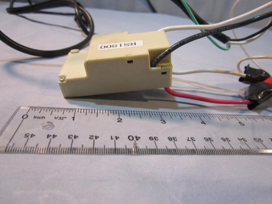
2AAMXRS1800
Aug 09, 2015Digital Transmission System
Equipment Class
DTS - Digital Transmission System
2AAMXSCD1000
May 19, 2015Digital Transmission System
Equipment Class
DTS - Digital Transmission System
2AAMXSS1200
Mar 24, 2014SS1200
Equipment Class
DTS - Digital Transmission System