2AAMXSCD1000Digital Transmission System
Ideal Industries, Inc.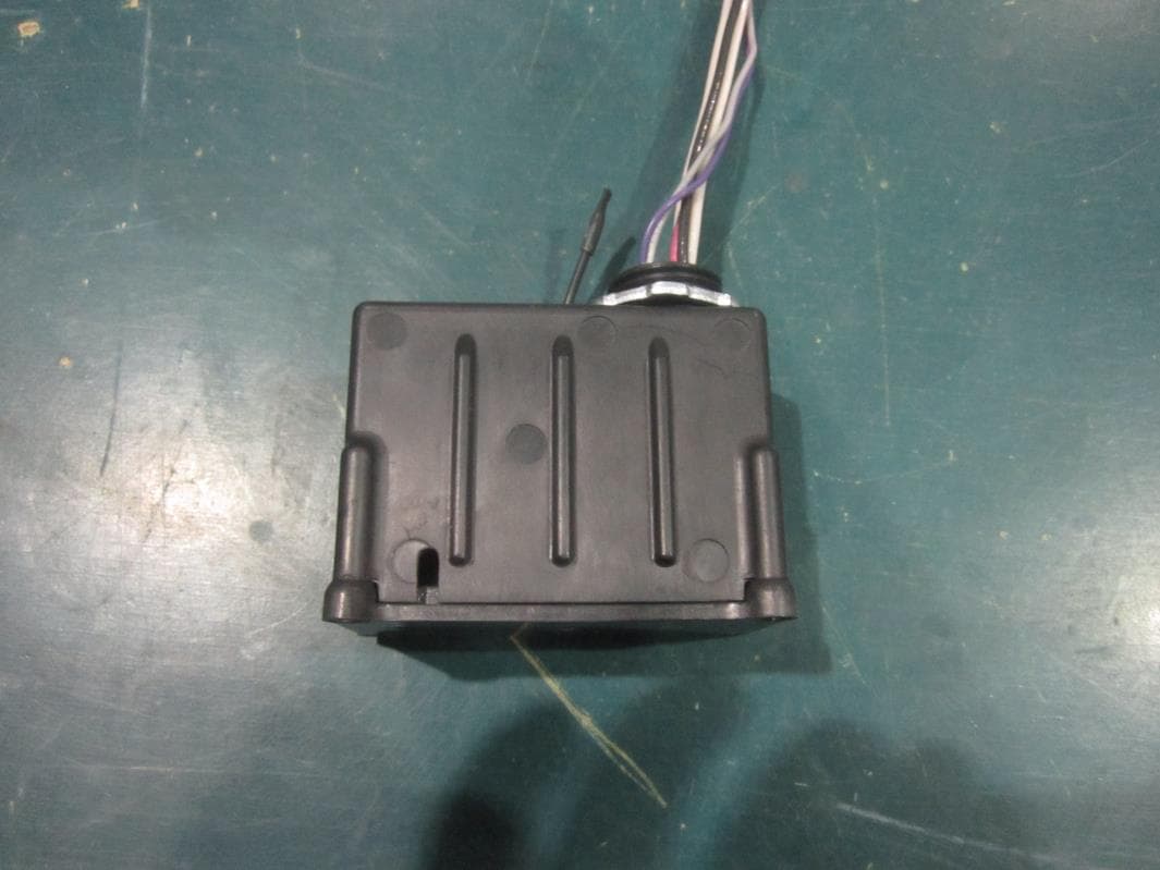
Click to zoom
Application Details
- Equipment Class
- DTS - Digital Transmission System
- Date of Grant
- May 19, 2015
- Application Purpose
- Original Equipment
- Date of Application
- May 18, 2015
- Equipment Note
- Digital Transmission System
- Frequency Range
- 902.00000000 - 928.00000000
- Company
- Ideal Industries, Inc.
- Country
- United States
Documents & Files
Document Text
Text extracted from the exhibit documents filed with the FCC. Open a document above to read the original.
Users Manual
Product Manual SCD1000 – Downlight/LED Smart Connector ND 7943-1 07/2014 Users Manual – SCD1000 Downlight/LED Smart Connector Page 1 www.idealindustries.com PRODUCT DESCRIPTION The AC Smart Connector is a wireless device which provides electrical connectivity between the light fixture (load) and 120V/277V AC line power and provides on/off power control and dimming signals to the load. The information that tells the connector to power on/off/dim the fixture is acquired via wireless signals that originate from a building automation system or from room controls, based on environmental conditions and/or predetermined programs. KEY FEATURES FCC and IC approved External fixture mounting Small form factor Integrated Wire Antenna RoHS compliant PRODUCT CONTENTS The following items are included inside the package: Qty Description 1 SCD1000 Smart Connector Audacy®, Smart Connector® and Smart Switch® are registered trademarks of IDEAL INDUSTRIES. All other trademarks are the property of their respective owners. Product Manual SCD1000 – Downlight/LED Smart Connector ND 7943-1 07/2014 Users Manual – SCD1000 Downlight/LED Smart Connector Page 2 www.idealindustries.com IDEAL Model SCD1000 Downlight/LED Smart Connector Installation Instructions WARNING: This is a current rated device. Use in applications involving amperage beyond its rating can be dangerous and cause electrical fires. Wiring must comply with all applicable electrical codes. Turn off power before removing or installing connector. TERMINOLOGY LINE(Black): Smart Connector power feed to be connected to premise wiring LOAD(Red): Power output from Smart Connector to ballast AC power input Neutral(White): Incoming Neutral from premise wiring and outgoing ballast neutral. DIM (Purple/Grey): 0-10 VDC dimming control output from Smart Connector to ballast dimming input CONNECTING THE WIRES Input Power The smart connector LINE(Black) and NEUTRAL(White) wires are 18 AWG solid copper conductors. 1. Strip wires to 1/2”. 2. Connect Smart Connector Line Input to premise line power feed with appropriate sized wirenut or push-in connector. 3. Connect Smart Connector Neutral Input to premise neutral feed with appropriately sized wirenut or push-in connector.. 4. For feed-through (i.e., “daisy-chain”) installations, connect the LINE hot feed-through conductor into the wirenut in step 2. Also, connect the NEUTRAL feet-through conductor connected without re-installing the wires. into the wirenut in step 3. Product Manual SCD1000 – Downlight/LED Smart Connector ND 7943-1 07/2014 Users Manual – SCD1000 Downlight/LED Smart Connector Page 3 www.idealindustries.com LOAD The LOAD(red) and Neutral(White) wire are 18 AWG solid copper conductors. 1. Strip wires to 1/2”. 2. Connect Smart Connector LOAD wire to the ballast hot line with appropriate sized wirenut or push-in connector if necessary. 3. Connect Smart Connector NEUTRAL Output to the ballast neutral with appropriately sized wirenut or push-in connector if necessary. 4. For feed-through (i.e., “daisy-chain”) installations, connect the LOAD hot feed-through conductor into the wirenut in step 2. Also, connect the NEUTRAL Output feed-through conductor into the wirenut in step 3. DIM Connector The DIM wires are18 AWG solid copper conductors. 1. Strip wires to 1/2”. 2. Connect positive/(+)/purple DIM wire from Smart Connector to positive/(+)/purple wire from dimming ballast with appropriate sized wirenut or push-in connector if necessary. 3. Connect negative/(-)/grey DIM wire from Smart Connector to negative/(-)/grey wire from dimming ballast with appropriate sized wirenut or push-in connector if necessary. Figure 1 – Typical Installation Product Manual SCD1000 – Downlight/LED Smart Connector ND 7943-1 07/2014 Users Manual – SCD1000 Downlight/LED Smart Connector Page 4 www.idealindustries.com PROGRAMMING Refer to the Audacy™ system configuration manual to associate smart connectors to other devices and to set up operating parameters for the Audacy™ lighting control system SPECIFICATIONS Item Description Radio 915 MHz External Antenna Regulatory Approvals FCC Part 15 and Industry Canada Contains FCC ID: 2AAMXSDL1000 Contains IC: 11250A-SDL1000 UL916 Transmit Range 300 ft. indoors line of sight to an Audacy Gateway or Smart Connector Load Dimming 0-10VDC (10%-100%) Load Amperage 5A Switching Cycles 50,000 Power 120VAC/277VAC Operating Temperature 0°C to 70°C Storage Temperature -20°C to 90°C Installation Environment Indoor use only Dimensions 4.67”x1.75”x0.99” Weight 3.3 oz Warranty 1 yr MECHANICAL DIMENSIONS Product Manual SCD1000 – Downlight/LED Smart Connector ND 7943-1 07/2014 Users Manual – SCD1000 Downlight/LED Smart Connector Page 5 www.idealindustries.com *Dimensions in inches Product Manual SCD1000 – Downlight/LED Smart Connector ND 7943-1 07/2014 Users Manual – SCD1000 Downlight/LED Smart Connector Page 6 www.idealindustries.com SUPPORT Technical support for IDEAL INDUSTRIES products can be initiated through the following methods: Website: http://www.idealindustries.com/support/ Telephone: +1 800-435-0705 Email: [email protected] Product Manual SCD1000 – Downlight/LED Smart Connector ND 7943-1 07/2014 Users Manual – SCD1000 Downlight/LED Smart Connector Page 7 www.idealindustries.com COMPLIANCE STATEMENTS This device is intended for commercial and industrial applications. Changes or modifications not expressly approved by IDEAL could void the user’s authority to operate the equipment. Use and maintain device only as specified in this manual. This equipment has been tested and found to comply with the limits for a Class B digital device, pursuant to Part 15 of the FCC Rules. These limits are designed to provide reasonable protection against harmful interference in a residential installation. This equipment generates, uses, and can radiate radio frequency energy and, if not installed and used in accordance with the instructions, may cause harmful interference to radio communications. However, the…
Text truncated - open the document above for the full version.
RF Exposure Info
Prediction of MPE limit at a given distance Equation from page 18 of OET Bulletin 65, Edition 97-01 where: S = power density P = power input to the antenna G = power gain of the antenna in the direction of interest relative to an isotropic radiator R = distance to the center of radiation of the antenna Maximum peak output power at the antenna terminal: 19.45 (dBm) Maximum peak output power at the antenna terminal: 88.1048873 (mW) Antenna gain(typical): 4.55 (dBi) Maximum antenna gain: 2.851018268 (numeric) Prediction distance: 20 (cm) Prediction frequency: 902.7 (MHz) MPE limit for uncontrolled exposure at prediction frequency: 0.6018 (mW/cm 2 ) Power density at prediction frequency: 0.049972 (mW/cm 2 ) 0.499723928 W/m 2 Therefore device complies with FCC RF radiation exposure limits for general population in mobile exposure category (distance > 20cm) 2 4 R PG S
Test Report
Curtis-Straus LLC is accredited by the American Association for Laboratory Accreditation for the specific scope of accreditation under Certificate Number 1627-01. This report may contain data which is not covered by the A2LA accreditation. ____________________________________________________________ Curtis-Straus LLC, a wholly owned subsidiary of BV CPS One Distribution Center Circle, #1 Littleton, MA TEL (978) 486-8880 FAX (978) 486-8828 page 1 of 28 Test Report Curtis-Straus LLC, a wholly owned subsidiary of BV CPS Report No EO0675-1 Client Powercast Corporation Charlie Greene Address 566 Alpha Drive Pittsburgh, PA 15238 Phone 412-436-4077 Items tested SCD1000 AND SCLED1000 FCC ID IC 2AAMXSCD1000 11250A-SCD1000 FRN 0002862225 Equipment Type Part 15.247 Digitally Modulated Equipment Code DTS FCC/IC Rule Parts 47 CFR 15.247, RSS-210 Issue 8, RSS GEN Issue 3 Test Dates May 7 – 9 and June 11, 2014 Results As detailed within this report Prepared by Tuyen Truong A. – Test Engineer Authorized by Christopher Reynolds – EMC Supervisor Issue Date 6/30/2014 Conditions of Issue This Test Report is issued subject to the conditions stated in the ‘Conditions of Testing’ section on page 27 of this report. Test Report for Powercast Corporation. Report No. EO0675-1 June 16, 2014 ______________________________________________________________________ ____________________________________________________________ Curtis-Straus LLC, a wholly owned subsidiary of BV CPS One Distribution Center Circle, #1 Littleton, MA TEL (978) 486-8880 FAX (978) 486-8828 page 2 of 28 Contents Contents .................................................................................................................................. 2 Summary ................................................................................................................................. 3 Test Methodology .................................................................................................................... 4 Product Tested - Configuration Documentation ....................................................................... 5 Statement of Conformity ...................................................................................................... 6 Test Results ............................................................................................................................ 7 Bandwidth ............................................................................................................................ 7 Fundamental Emission Output Power ................................................................................ 10 Radiated Spurious Emissions ............................................................................................ 13 Conducted Spurious Emissions ......................................................................................... 16 Power Spectral Density ...................................................................................................... 18 AC Line Conducted Emissions ........................................................................................... 21 Occupied Bandwidth .......................................................................................................... 23 Measurement Uncertainty...................................................................................................... 26 Conditions Of Testing ............................................................................................................ 27 Form Final Report REV 7-20-07 (DW) Test Report for Powercast Corporation. Report No. EO0675-1 June 16, 2014 ______________________________________________________________________ _____________________________________________________________ Curtis-Straus LLC, a wholly owned subsidiary of BV CPS One Distribution Center Circle, #1 Littleton, MA TEL (978) 486-8880 FAX (978) 486-8828 page 3 of 28 Summary This test report supports an application for certification of a transmitter operating pursuant to 47 CFR 15.247. The products are the SCD1000 AND SCLED1000. They are digitally modulated transmitters that operate in the range 902-928MHz. Products were tested with an on board antenna with a gain of 4.55dBi. We found that the products met the above requirements without modification. Charlie Greene from Powercast Corporation was present during the testing. The test samples were received in good condition. Please note that The SCD1000 and SCLED1000 differ only in where the dimming wires (purple and gray) exit the enclosure. The SCD1000 has all wires exiting through the nipple. The SCLED1000 has the purple and gray dimming wires exiting away from the high voltage wires but does not cross the board. Therefore, Radiated Spurious Emissions and AC Line Conducted Emissions testing were separately performed for each model. Only conducted testing at the Antenna port was performed once. Test Report for Powercast Corporation. Report No. EO0675-1 June 16, 2014 ______________________________________________________________________ _____________________________________________________________ Curtis-Straus LLC, a wholly owned subsidiary of BV CPS One Distribution Center Circle, #1 Littleton, MA TEL (978) 486-8880 FAX (978) 486-8828 page 4 of 28 Test Methodology Radiated emission and AC Line conducted testing were performed according to the procedures specified in FCC Guidance for performing compliance measurement on DTS operating under section 15.247, April 19, 2013 and ANSI C63.10 (2009) and C63.4 (2003). Radiated Emissions were maximized by rotating the device around its axes as well as varying the test antenna’s height and polarity. The antenna was maximized separately. Conducted emissions at the antenna port were performed, as required by rule section. The EUT operating voltage is 120VAC, 60Hz Low operating channel frequency = 902.7MHz Mid operating channel frequency = 915MHz High operating channel frequency = 927…
Text truncated - open the document above for the full version.
Test Setup Photos
Conducted Test at the Antenna Port Radiated Emission
Contact Information
Applicant
Tim Tunnell(Sr. Electrical Engineer)
Test Firm
BUREAU VERITAS CONSUMER PRODUCTS SERVICES, INC.Ozgur Ozturk
[email protected]978-486-8880
Technical Specifications
| # | Rule Parts | Frequency Range | Power Output |
|---|---|---|---|
| 1 | 15C | 902 MHz - 928 MHz | 88.00 mW |
Other Applications from Ideal Industries, Inc.
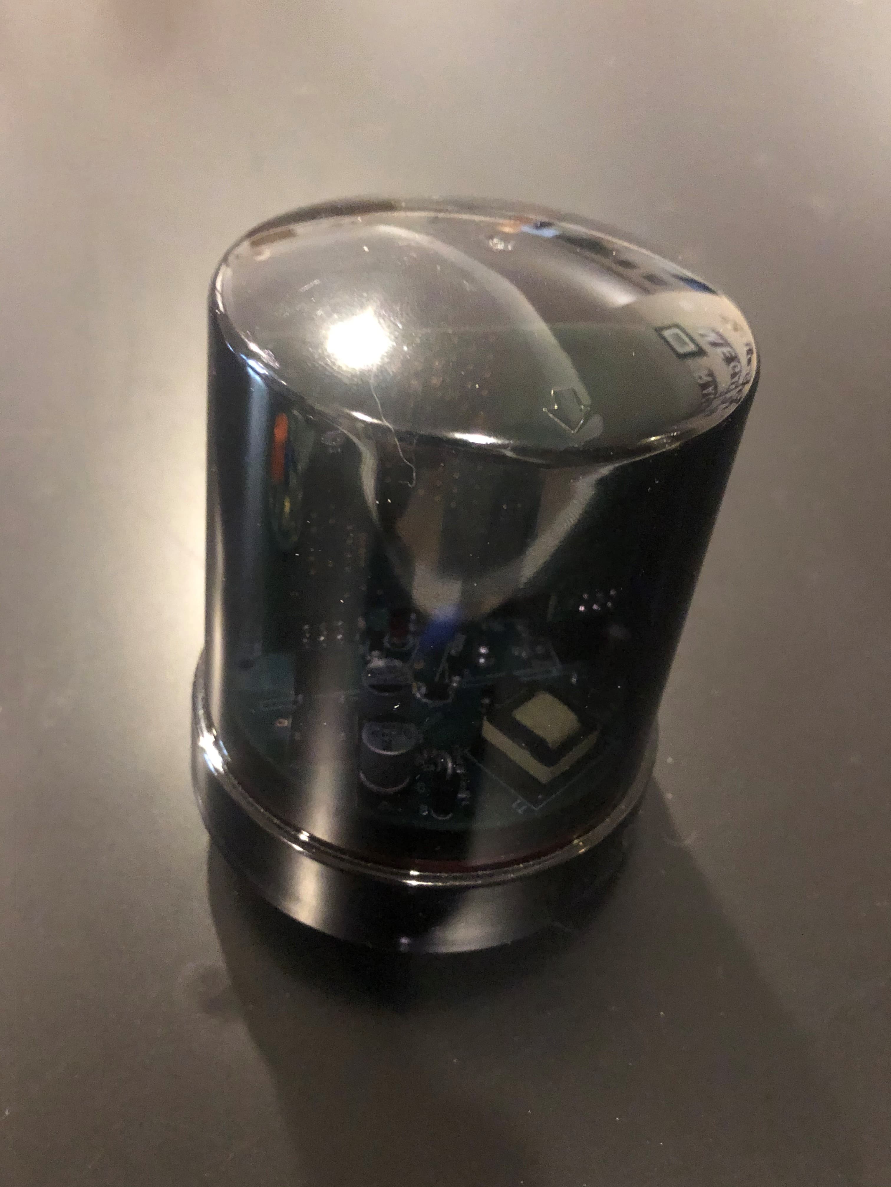
2AAMXNEMA10DIM
Sep 24, 2020NEMA Controller, 120/277VAC 5A 0-10V
Equipment Class
DTS - Digital Transmission System
2AAMXIBRIDGE
Mar 12, 20204 Port Contact Closure Toggle Switch
Equipment Class
DTS - Digital Transmission System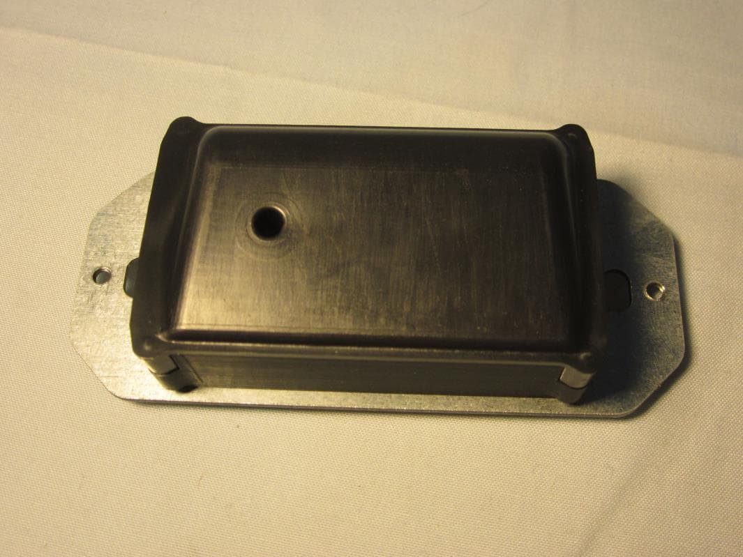
2AAMXWMS1200
Jan 27, 2016Smart Switch
Equipment Class
DTS - Digital Transmission System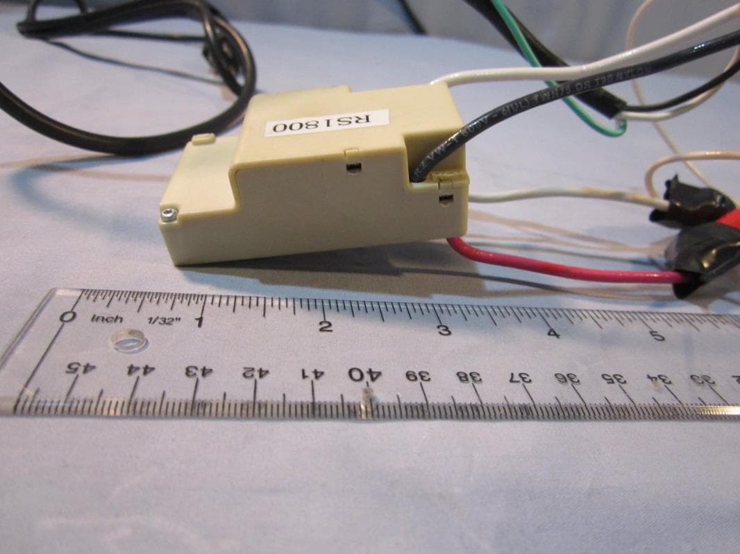
2AAMXRS1800
Aug 09, 2015Digital Transmission System
Equipment Class
DTS - Digital Transmission System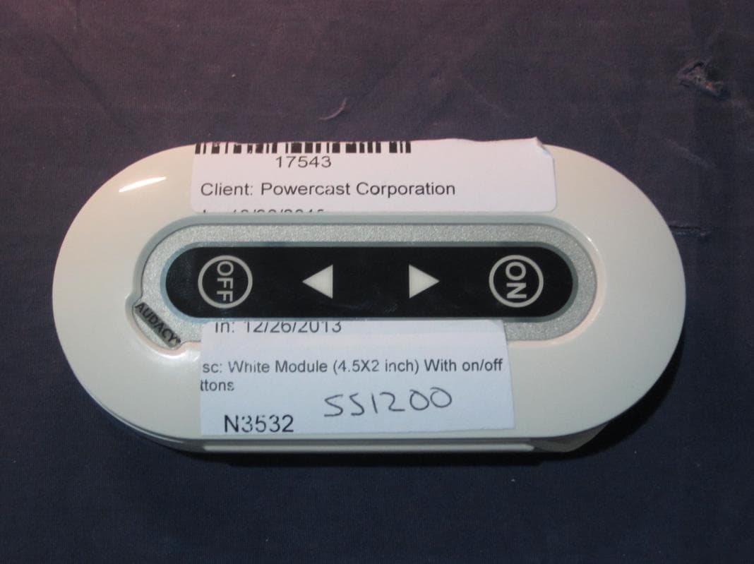
2AAMXSS1200
Mar 24, 2014SS1200
Equipment Class
DTS - Digital Transmission System