2AAOY-SBP5Bluetooth Speaker
Mitek Corp
Click to zoom
Application Details
- Equipment Class
- DSS - Part 15 Spread Spectrum Transmitter
- Date of Grant
- Apr 25, 2021
- Application Purpose
- Original Equipment
- Date of Application
- Apr 25, 2021
- Equipment Note
- Bluetooth Speaker
- Frequency Range
- 2402.00000000 - 2480.00000000
- Company
- Mitek Corp
- Country
- United States
Documents & Files
Document Text
Text extracted from the exhibit documents filed with the FCC. Open a document above to read the original.
Users Manual
PAGE 1 302719 DPF-MRK-003 REV E 3/22/21 ROAD THUNDER SOUND BAR PLUS BY MTX, SATIN SILVER2719 866 277 9598 | [email protected] 454 COUNTY ROAD VV SOMERSET, WI 54025 KURYAKYN.COM INSTALLATION INSTRUCTIONS THANK YOU FOR CHOOSING KURYAKYN! Protect yourself and others from possible injury and property damage or loss. Pay close attention to all instructions, warnings, cautions, and notices regarding the installation, use, and care of this product. THIS INDICATION ALERTS YOU TO THE FACT THAT IGNORING THE CONTENTS DESCRIBED HEREIN CAN RESULT IN POTENTIAL DEATH OR SERIOUS INJURY. THIS INDICATION ALERTS YOU TO THE FACT THAT IGNORING THE CONTENTS DESCRIBED HEREIN CAN RESULT IN MINOR OR MODERATE POTENTIAL INJURY. THIS INDICATION ALERTS YOU TO THE FACT THAT IGNORING THE CONTENTS DESCRIBED HEREIN MAY NEGATIVELY AFFECT PRODUCT PERFORMANCE AND FUNCTIONALITY OR DAMAGE THE PRODUCT ITSELF OR THE PRODUCT TO WHICH IT IS BEING ATTACHED. YOU WILL ALSO NEED: Metric Hex, Allen wrenches, pliers THE EQUIPMENT COMPLIES WITH FCC RADIATION EXPOSURE LIMITS SET FORTH FOR AN UNCONTROLLED ENVIRONMENT. THE EQUIPMENT SHOULD BE INSTALLED AND OPERATED WITH MINIMUM DISTANCE 20CM BETWEEN THE RADIATOR AND YOUR BODY. THESE INSTALLATION INSTRUCTIONS CONTAIN IMPORTANT INFORMATION. ENSURE THE END USER RECEIVES THIS COPY AND IS AWARE OF ITS IMPORTANCE FOR FUTURE USE. WHEN CONNECTING POWER AND GROUND WIRES ENSURE THAT THE RED POWER WIRE IS FUSED AT THE POINT WHERE IT IS CONNECTED TO THE VEHICLE’S BATTERY. FAILURE TO DO SO CAN RESULT IN DAMAGE TO THE VEHICLE IF A SHORT CIRCUIT DEVELOPS BETWEEN THE VEHICLE CONNECTION POINT AND THE PRODUCT. ENSURE THAT THE FOLLOWING PARTS HAVE BEEN INCLUDED IN THE KIT: 1Road Thunder Sound Bar Plus with Wire Harness 1Hardware Kit, containing: 2M6-1.0 X 35MM Button Head Hex Screws 2Sound Bar Mounting Clamps2M6-1.0 Lock Nut w/Washers 27/8” Clamps2M6-1.0 X 11MM Cap Screw Hex Drive 21” Clamps2M6 Split Washers 21-1/8” Clamps2M4-0.7 X 10MM Set Screws 21-1/4” Clamps12MM Allen Wrench 21-1/2” Clamps17.5 Amp Mini Fuse (Red Power Wire) 1USB Rubber Plug Seal12 Amp Mini Fuse (Orange ACC/Key Wire) 1Transparent Film1T-Tap Quick Connect Female 4Cable Ties 1” CLAMP 1-1/8” CLAMP 1-1/4” CLAMP 1-1/2” CLAMP 7/8” CLAMP 2MM ALLEN WRENCH TRASNPARENT FILM CABLE TIES SOUND BAR MOUNTING CLAMPS ROAD THUNDER SOUND BAR PLUS WIRE HARNESS 2 AMP FUSE 7.5 AMP FUSE M6-1 X 35MM BHHS USB RUBBER PLUG SEAL M6-1 X 11M M CSHD SPLIT WASHERS SET SCREWS T-TAP QUICK CONNECTS M6-1 LOCK NUT CHANGES OR MODIFICATIONS TO THIS UNIT NOT EXPRESSLY APPROVED BY THE PARTY RESPONSIBLE FOR COMPLIANCE COULD VOID THE USER’S AUTHORITY TO OPERATE THE EQUIPMENT. PAGE 2 302719 DPF-MRK-003 REV E 3/22/21 ROAD THUNDER SOUND BAR PLUS BY MTX, SATIN SILVER2719 866 277 9598 | [email protected] 454 COUNTY ROAD VV SOMERSET, WI 54025 KURYAKYN.COM INSTALLATION INSTRUCTIONS -CONTINUED- INTRODUCTION Thank you for purchasing this Kuryakyn Road Thunder Sound Bar Plus by MTX that is designed to work with most Bluetooth enabled devices including iPhone® and Android® smartphones and tablets. This easy to install and use, all in one unit is capable of transforming your Bluetooth enabled mobile device into the center of your vehicle’s audio system. It is designed to mount on a variety of bars between 7⁄ 8” and 1-1⁄ 2”. Congratulations and enjoy the ultimate audio experience! FEATURES • Two 2” x 3” full range speakers and four 1” high frequency tweeters • All-weather construction for use in almost any environment • Integrated Bluetooth receiver • Auxiliary input for connecting devices via 3.5mm cable • Auxiliary output for connecting an external amplifier or additional sound bar via 3.5mm cable • Universal mounting clamps fit bars between 7⁄ 8” and 1-1⁄ 2” • Power, ground, ignition wire, and 12v trigger output included for easy installation • Automated Bluetooth pairing via NFC • 1.0 Amp USB charging port INSTALLATION The Road Thunder Sound Bar Plus can be used with any 12-volt battery and can be mounted to a variety of bars using the included hardware. The unit has four wires in its wiring pigtail. The red wire, hot, should be directly connected to the vehicles positive battery terminal. The black wire, ground, should be connected directly to the vehicle’s chassis where paint has been removed or the negative terminal on the battery. Use the included T-Tap Quick Connect Female connector and install directly onto the ACC/Key ignition wire on the motorcycle using a pair of pliers. Connect the Quick Connect Male connector, located on the orange wire, and the T-Tap Quick Connect Female together. The blue wire, optional output, can be used to turn on additional amplifiers. The unit features fully adjustable clamps for mounting to bars between 7⁄ 8” and 1-1⁄ 2”. The clamps can be used to mount to many styles of handlebar and roll bar systems. The included brackets are versatile, so mounting to angled bars is possible. SCENARIO 1 - MOUNT CLAMPS TO HANDLEBAR FIRST, THEN INSTALL SOUND BAR. • Choose the correct size strap clamp for the handlebars. Note: placing the transparent film between the strap clamp and handlebar will reduce the possibility of scratching the handlebars during installation. • Assemble mid-section to bottom bracket using included 5mm Allen screw and 10mm hex nut. • Ensure that the spacing between the brackets is between 3” and 6.75”. • Slide the sound bar into the brackets from the left side, so the brackets can clear the buttons without damaging them. • Rotate the sound bar so the speakers are directed at the rider’s head. • Tighten the 5mm Allen screws to lock the sound bar in place. • Tighten the 2mm set screws. • Connect wires to power, ground, and ignition. PAGE 3 302719 DPF-MRK-003 REV E 3/22/21 ROAD THUNDER SOUND BAR PLUS BY MTX, SATIN SILVER2719 866 277 9598 | [email protected] 454 COUNTY ROAD VV SOMERSET, WI 54025 KURYAKYN.COM INSTALLATION INSTRUCTIONS INSTALLATION SCENARIO 2 - INSTALL SOUND BAR, THEN MOUNTS CLAMPS TO HANDLEBAR. • Choose the correct size strap clamp f…
Text truncated - open the document above for the full version.
Users Manual
PAGE 1 302720 DPF-MRK-003 REV E 3/22/21 ROAD THUNDER SOUND BAR PLUS BY MTX, SATIN BLACK2720 866 277 9598 | [email protected] 454 COUNTY ROAD VV SOMERSET, WI 54025 KURYAKYN.COM INSTALLATION INSTRUCTIONS THANK YOU FOR CHOOSING KURYAKYN! Protect yourself and others from possible injury and property damage or loss. Pay close attention to all instructions, warnings, cautions, and notices regarding the installation, use, and care of this product. THIS INDICATION ALERTS YOU TO THE FACT THAT IGNORING THE CONTENTS DESCRIBED HEREIN CAN RESULT IN POTENTIAL DEATH OR SERIOUS INJURY. THIS INDICATION ALERTS YOU TO THE FACT THAT IGNORING THE CONTENTS DESCRIBED HEREIN CAN RESULT IN MINOR OR MODERATE POTENTIAL INJURY. THIS INDICATION ALERTS YOU TO THE FACT THAT IGNORING THE CONTENTS DESCRIBED HEREIN MAY NEGATIVELY AFFECT PRODUCT PERFORMANCE AND FUNCTIONALITY OR DAMAGE THE PRODUCT ITSELF OR THE PRODUCT TO WHICH IT IS BEING ATTACHED. YOU WILL ALSO NEED: Metric Hex, Allen wrenches, pliers THE EQUIPMENT COMPLIES WITH FCC RADIATION EXPOSURE LIMITS SET FORTH FOR AN UNCONTROLLED ENVIRONMENT. THE EQUIPMENT SHOULD BE INSTALLED AND OPERATED WITH MINIMUM DISTANCE 20CM BETWEEN THE RADIATOR AND YOUR BODY. THESE INSTALLATION INSTRUCTIONS CONTAIN IMPORTANT INFORMATION. ENSURE THE END USER RECEIVES THIS COPY AND IS AWARE OF ITS IMPORTANCE FOR FUTURE USE. WHEN CONNECTING POWER AND GROUND WIRES ENSURE THAT THE RED POWER WIRE IS FUSED AT THE POINT WHERE IT IS CONNECTED TO THE VEHICLE’S BATTERY. FAILURE TO DO SO CAN RESULT IN DAMAGE TO THE VEHICLE IF A SHORT CIRCUIT DEVELOPS BETWEEN THE VEHICLE CONNECTION POINT AND THE PRODUCT. ENSURE THAT THE FOLLOWING PARTS HAVE BEEN INCLUDED IN THE KIT: 1Road Thunder Sound Bar Plus with Wire Harness 1Hardware Kit, containing: 2M6-1.0 X 35MM Button Head Hex Screws 2Sound Bar Mounting Clamps2M6-1.0 Lock Nut w/Washers 27/8” Clamps2M6-1.0 X 11MM Cap Screw Hex Drive 21” Clamps2M6 Split Washers 21-1/8” Clamps2M4-0.7 X 10MM Set Screws 21-1/4” Clamps12MM Allen Wrench 21-1/2” Clamps17.5 Amp Mini Fuse (Red Power Wire) 1USB Rubber Plug Seal12 Amp Mini Fuse (Orange ACC/Key Wire) 1Transparent Film1T-Tap Quick Connect Female 4Cable Ties 1” CLAMP 1-1/8” CLAMP 1-1/4” CLAMP 1-1/2” CLAMP 7/8” CLAMP 2MM ALLEN WRENCH TRASNPARENT FILM CABLE TIES SOUND BAR MOUNTING CLAMPS ROAD THUNDER SOUND BAR PLUS WIRE HARNESS 2 AMP FUSE 7.5 AMP FUSE M6-1 X 35MM BHHS USB RUBBER PLUG SEAL M6-1 X 11M M CSHD SPLIT WASHERS SET SCREWS T-TAP QUICK CONNECTS M6-1 LOCK NUT CHANGES OR MODIFICATIONS TO THIS UNIT NOT EXPRESSLY APPROVED BY THE PARTY RESPONSIBLE FOR COMPLIANCE COULD VOID THE USER’S AUTHORITY TO OPERATE THE EQUIPMENT. PAGE 2 302720 DPF-MRK-003 REV E 3/22/21 ROAD THUNDER SOUND BAR PLUS BY MTX, SATIN BLACK2720 866 277 9598 | [email protected] 454 COUNTY ROAD VV SOMERSET, WI 54025 KURYAKYN.COM INSTALLATION INSTRUCTIONS -CONTINUED- INTRODUCTION Thank you for purchasing this Kuryakyn Road Thunder Sound Bar Plus by MTX that is designed to work with most Bluetooth enabled devices including iPhone® and Android® smartphones and tablets. This easy to install and use, all in one unit is capable of transforming your Bluetooth enabled mobile device into the center of your vehicle’s audio system. It is designed to mount on a variety of bars between 7⁄ 8” and 1-1⁄ 2”. Congratulations and enjoy the ultimate audio experience! FEATURES • Two 2” x 3” full range speakers and four 1” high frequency tweeters • All-weather construction for use in almost any environment • Integrated Bluetooth receiver • Auxiliary input for connecting devices via 3.5mm cable • Auxiliary output for connecting an external amplifier or additional sound bar via 3.5mm cable • Universal mounting clamps fit bars between 7⁄ 8” and 1-1⁄ 2” • Power, ground, ignition wire, and 12v trigger output included for easy installation • Automated Bluetooth pairing via NFC • 1.0 Amp USB charging port INSTALLATION The Road Thunder Sound Bar Plus can be used with any 12-volt battery and can be mounted to a variety of bars using the included hardware. The unit has four wires in its wiring pigtail. The red wire, hot, should be directly connected to the vehicles positive battery terminal. The black wire, ground, should be connected directly to the vehicle’s chassis where paint has been removed or the negative terminal on the battery. Use the included T-Tap Quick Connect Female connector and install directly onto the ACC/Key ignition wire on the motorcycle using a pair of pliers. Connect the Quick Connect Male connector, located on the orange wire, and the T-Tap Quick Connect Female together. The blue wire, optional output, can be used to turn on additional amplifiers. The unit features fully adjustable clamps for mounting to bars between 7⁄ 8” and 1-1⁄ 2”. The clamps can be used to mount to many styles of handlebar and roll bar systems. The included brackets are versatile, so mounting to angled bars is possible. SCENARIO 1 - MOUNT CLAMPS TO HANDLEBAR FIRST, THEN INSTALL SOUND BAR. • Choose the correct size strap clamp for the handlebars. Note: placing the transparent film between the strap clamp and handlebar will reduce the possibility of scratching the handlebars during installation. • Assemble mid-section to bottom bracket using included 5mm Allen screw and 10mm hex nut. • Ensure that the spacing between the brackets is between 3” and 6.75”. • Slide the sound bar into the brackets from the left side, so the brackets can clear the buttons without damaging them. • Rotate the sound bar so the speakers are directed at the rider’s head. • Tighten the 5mm Allen screws to lock the sound bar in place. • Tighten the 2mm set screws. • Connect wires to power, ground, and ignition. PAGE 3 302720 DPF-MRK-003 REV E 3/22/21 ROAD THUNDER SOUND BAR PLUS BY MTX, SATIN BLACK2720 866 277 9598 | [email protected] 454 COUNTY ROAD VV SOMERSET, WI 54025 KURYAKYN.COM INSTALLATION INSTRUCTIONS INSTALLATION SCENARIO 2 - INSTALL SOUND BAR, THEN MOUNTS CLAMPS TO HANDLEBAR. • Choose the correct size strap clamp for …
Text truncated - open the document above for the full version.
External Photos
Dongguan Dongdian Testing Service Co., Ltd. Report No.: DDT-R21021903-1E1 Page 60 of 69 16. Photos of the EUT Dongguan Dongdian Testing Service Co., Ltd. Report No.: DDT-R21021903-1E1 Page 61 of 69 Dongguan Dongdian Testing Service Co., Ltd. Report No.: DDT-R21021903-1E1 Page 62 of 69 Dongguan Dongdian Testing Service Co., Ltd. Report No.: DDT-R21021903-1E1 Page 63 of 69
Internal Photos
Dongguan Dongdian Testing Service Co., Ltd. Report No.: DDT-R21021903-1E1 Page 64 of 69 Dongguan Dongdian Testing Service Co., Ltd. Report No.: DDT-R21021903-1E1 Page 65 of 69 Dongguan Dongdian Testing Service Co., Ltd. Report No.: DDT-R21021903-1E1 Page 66 of 69 Dongguan Dongdian Testing Service Co., Ltd. Report No.: DDT-R21021903-1E1 Page 67 of 69 Dongguan Dongdian Testing Service Co., Ltd. Report No.: DDT-R21021903-1E1 Page 68 of 69 Dongguan Dongdian Testing Service Co., Ltd. Report No.: DDT-R21021903-1E1 Page 69 of 69 END OF REPORT BT Antenna
RF Exposure Info
Dongguan Dongdian Testing Service Co., Ltd Report No.:DDT-R21021903-1E2 Page 1 of 6 RF EXPOSURE REPORT FOR Issued By: Dongguan Dongdian Testing Service Co., Ltd. Add.: No. 17, Zongbu Road 2, Songshan Lake Sci&Tech, Industry Park, Dongguan City, Guangdong Province, China, 523808 Tel.: +86-0769-38826678, E-mail: [email protected], http://www.dgddt.com Applicant : Mitek Corp Address : 1 Mitek Plaza, Winslow, IL. 61089 Equipment under Test : Bluetooth Speaker Model No. : 2719, 2720, 2469293, 2469294 Trade Mark : / FCC ID : 2AAOY-SBP5 Manufacturer : Dongguan Jucheng Electronic Technology Co., Ltd. Address : Room 201, No. 2, Poling Street, Qingxi Town, Dongguan City, Guangdong Province ■Report No.: DDT-R21021903-1E2 ■Issued Date: Mar. 08, 2021 Dongguan Dongdian Testing Service Co., Ltd Report No.:DDT-R21021903-1E2 Page 2 of 6 Table of Contents Test report declares........................................................................................................3 1. General Information ...................................................................................................... 5 1.1. Description of equipment .............................................................................................. 5 1.2. Assess laboratory ......................................................................................................... 5 2. RF Exposure Evaluation ............................................................................................... 5 2.1. Requirement ................................................................................................................. 5 2.2. Calculation method ....................................................................................................... 6 2.3. Estimation result ........................................................................................................... 6 Dongguan Dongdian Testing Service Co., Ltd Report No.:DDT-R21021903-1E2 Page 3 of 6 Test Report Declare Standard Used: KDB447498 D01 General RF Exposure Guidance v06 We Declare: The equipment described above is assessed by Dongguan Dongdian Testing Service Co., Ltd and in the configuration assessed the equipment complied with the standards specified above. The assessed results are contained in this report and Dongguan Dongdian Testing Service Co., Ltd is assumed of full responsibility for the accuracy and completeness of these assess. After evaluation, our opinion is that the equipment In Accordance with above standard. Report No: DDT-R21021903-1E2 Date of Receipt: Feb. 25, 2021 Date of Test: Feb. 25, 2021 ~ Mar. 08, 2021 Prepared By: Approved By: _______________ _____________________ Sam Li/Engineer Damon Hu/EMC Manager Note: This report applies to above tested sample only. This report shall not be reproduced in parts without written approval of Dongguan Dongdian Testing Service Co., Ltd. Applicant : Mitek Corp Address : 1 Mitek Plaza, Winslow, IL. 61089 Equipment under Test : Bluetooth Speaker Model No. : 2719, 2720, 2469293, 2469294 Trade mark : / Manufacturer : Dongguan Jucheng Electronic Technology Co., Ltd. Address : Room 201, No. 2, Poling Street, Qingxi Town, Dongguan City, Guangdong Province Dongguan Dongdian Testing Service Co., Ltd Report No.:DDT-R21021903-1E2 Page 4 of 6 Revision History Rev. Revisions Issue Date Revised By --- Initial issue Mar. 08, 2021 Dongguan Dongdian Testing Service Co., Ltd Report No.:DDT-R21021903-1E2 Page 5 of 6 1. General Information 1.1. Description of equipment 1.2. Assess laboratory Dongguan Dongdian Testing Service Co., Ltd. Add.: No. 17, Zongbu Road 2, Songshan Lake Sci&Tech, Industry Park, Dongguan City, Guangdong Province, China, 523808 Tel.: +86-0769-38826678, http://www.dgddt.com, Email: [email protected] CNAS Registration No. CNAS L6451; A2LA Certificate Number: 3870.01; FCC Designation Number: CN1182; FCC Test Firm Registration Number: 540522 Industry Canada Site Registration Number: 10288A-1; CAB identifier: CN0048 2. RF Exposure Evaluation 2.1. Requirement Systems operating under the provisions of FCC 47 CFR section shall be operated in a manner that ensures that the public is not exposed to radio frequency energy level in excess of the Commission’s guidelines. In accordance with 47 CFR FCC Part 2 Subpart J, section 2.1091 this device has been defined as mobile device whereby a distance of 0.2 m normally can be maintained between the user and the device, and below RF Permissible Exposure limit shall comply with. Limits for General Population/Uncontrolled Exposure EUT* Name : Bluetooth Speaker Model Number : 2719, 2720, 2469293, 2469294 Difference of model number : All models are identical except the appearance and model number, therefore the test performed on the model 2719. EUT function description : Please reference user manual of this device Power Supply : DC 12V Radio Specification : Bluetooth V5.0 Operation Frequency : 2402 MHz - 2480 MHz Modulation : GFSK, /4-DQPSK, 8DPSK Data Rate : 1 Mbps, 2 Mbps, 3 Mbps Antenna Type : Integral PCB antenna, maximum PK gain: -0.58 dBi Serial Number : N/A Dongguan Dongdian Testing Service Co., Ltd Report No.:DDT-R21021903-1E2 Page 6 of 6 2.2. Calculation method From the peak EUT RF output power, the minimum mobile separation distance, d= 0.2 m, as well as the gain of the used antenna, the RF power density can be obtained. 2.3. Estimation result Mode PK Output power (dBm) Output power (mW) Antenna Gain (dBi) Antenna Gain (linear) MPE Values (mW/cm 2 ) MPE Limit (mW/cm 2 ) Bluetooth Max power 1.61 1.45 -0.58 0.87 0.00025 1 Note: The estimation distance is 20 cm Conclusion: The measurement results comply with the FCC Limit per 47 CFR 2.1091 for the uncontrolled RF Exposure of mobile device. END OF REPORT
Test Report
Dongguan Dongdian Testing Service Co., Ltd. Report No.: DDT-R21021903-1E1 Page 1 of 58 FCC CERTIFICATION TEST REPORT FOR Issued By: Dongguan Dongdian Testing Service Co., Ltd. Add.: No. 17, Zongbu Road 2, Songshan Lake Sci&Tech, Industry Park, Dongguan City, Guangdong Province, China, 523808 Tel.: +86-0769-38826678, E-mail: [email protected], http://www.dgddt.com Applicant : Mitek Corp Address : 4545 E Baseline Rd, Phoenix, Arizona, United States Equipment under Test : Bluetooth Speaker Model No. : 2719, 2720, 2469293, 2469294 Trade Mark : / FCC ID : 2AAOY-SBP5 Manufacturer : Dongguan Jucheng Electronic Technology Co., Ltd. Address : Room 201, No. 2, Poling Street, Qingxi Town, Dongguan City, Guangdong Province ■Report No.: DDT-R21021903-1E1 ■Issued Date: Mar. 08, 2021 Dongguan Dongdian Testing Service Co., Ltd. Report No.: DDT-R21021903-1E1 Page 2 of 58 Table of Contents Test report declares........................................................................................................4 1. Summary of Test Results ............................................................................................... 6 2. General Test Information ............................................................................................... 7 2.1. Description of EUT ......................................................................................................... 7 2.2. Accessories of EUT ........................................................................................................ 8 2.3. Assistant equipment used for test .................................................................................. 8 2.4. Block diagram of EUT configuration for test .................................................................. 8 2.5. Deviations of test standard ............................................................................................. 8 2.6. Test environment conditions .......................................................................................... 8 2.7. Test laboratory................................................................................................................ 9 2.8. Measurement uncertainty ............................................................................................... 9 3. Equipment Used During Test ....................................................................................... 10 4. Maximum Peak Output Power ..................................................................................... 12 4.1. Block diagram of test setup .......................................................................................... 12 4.2. Limits ............................................................................................................................ 12 4.3. Test procedure ............................................................................................................. 12 4.4. Test result ..................................................................................................................... 12 4.5. Original test data .......................................................................................................... 13 5. 20 dB Bandwidth and 99% Bandwidth ......................................................................... 15 5.1. Block diagram of test setup .......................................................................................... 15 5.2. Limits ............................................................................................................................ 15 5.3. Test procedure ............................................................................................................. 15 5.4. Test result ..................................................................................................................... 15 5.5. Original test data .......................................................................................................... 16 6. Carrier Frequency Separation ...................................................................................... 18 6.1. Block diagram of test setup .......................................................................................... 18 6.2. Limits ............................................................................................................................ 18 6.3. Test procedure ............................................................................................................. 18 6.4. Test result ..................................................................................................................... 18 6.5. Original test data .......................................................................................................... 19 7. Number of Hopping Channel ....................................................................................... 20 7.1. Block diagram of test setup .......................................................................................... 20 7.2. Limits ............................................................................................................................ 20 7.3. Test procedure ............................................................................................................. 20 7.4. Test result ..................................................................................................................... 20 7.5. Original test data .......................................................................................................... 20 Dongguan Dongdian Testing Service Co., Ltd. Report No.: DDT-R21021903-1E1 Page 3 of 58 8. Dwell Time ................................................................................................................... 22 8.1. Block diagram of test setup .......................................................................................... 22 8.2. Limits ..............................................................................…
Text truncated - open the document above for the full version.
Test Setup Photos
Dongguan Dongdian Testing Service Co., Ltd. Report No.: DDT-R21021903-1E1 Page 59 of 68 15. Test Setup Photograph
Contact Information
Applicant
Simon Broadley(VP of Engineering)
Technical Contact
Dongguan Dongdian Testing Service Co., LtdDamon Hu
[email protected]86-0769- 38826678
Dongguan · China
Non-Technical Contact
Dongguan Dongdian Testing Service Co., LtdDamon Hu
[email protected]86-0769- 38826678
Test Firm
Guangdong Dongdian Testing Service Co., Ltd.Mr. Jamy Yu
[email protected]+86-0769-89201646
Technical Specifications
| # | Rule Parts | Frequency Range | Power Output |
|---|---|---|---|
| 1 | 15C | 2.40 GHz - 2.48 GHz | 1.45 mW |
Other Applications from Mitek Corp
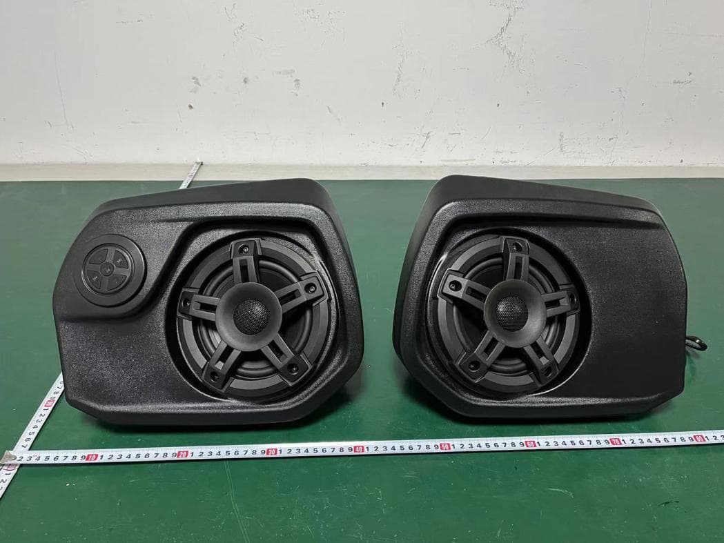
2AAOY-715005354
Mar 23, 2023BRP ATV Sound System
Equipment Class
DSS - Part 15 Spread Spectrum Transmitter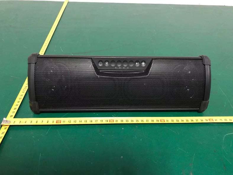
2AAOY27212724
Jan 26, 2021WANDERBAR PORTABLE SOUNDBAR
Equipment Class
DSS - Part 15 Spread Spectrum Transmitter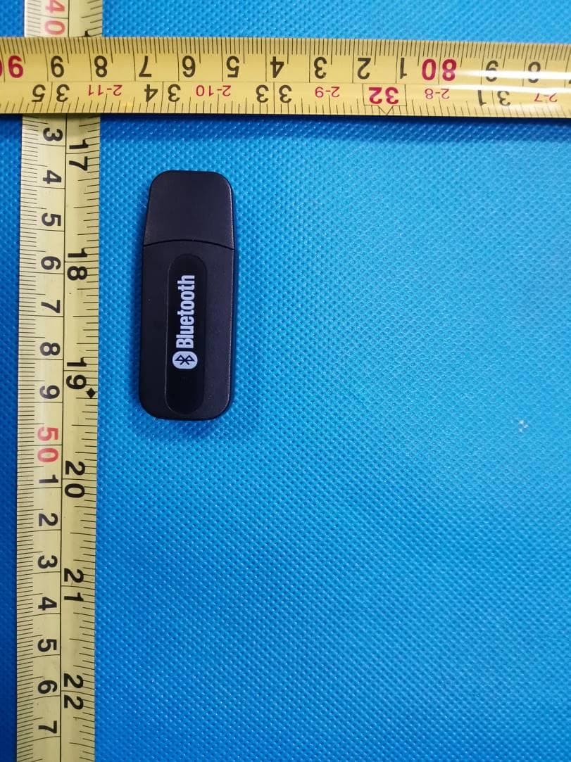
2AAOY-710005958
May 14, 2020AUDIO BLUETOOTH MODULE
Equipment Class
DSS - Part 15 Spread Spectrum Transmitter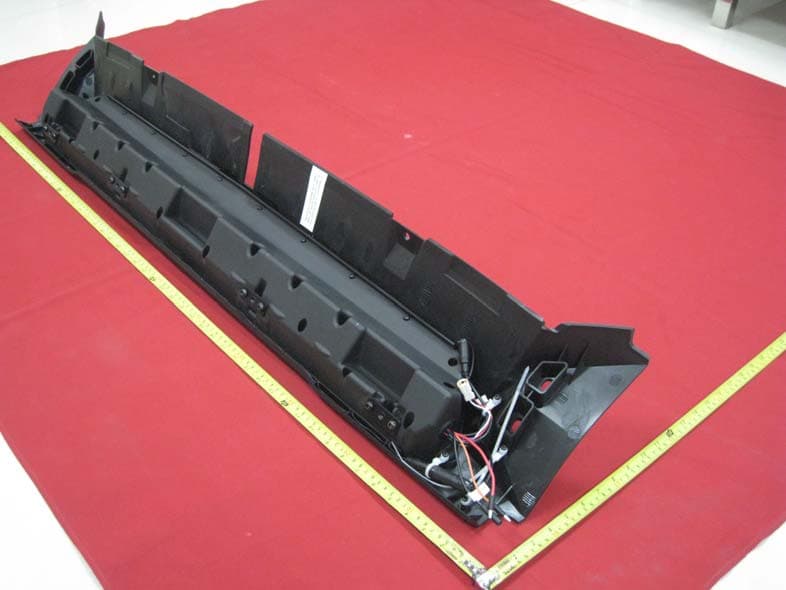
2AAOY-2635986
Dec 14, 2015Overhead Audio Unit
Equipment Class
DSS - Part 15 Spread Spectrum Transmitter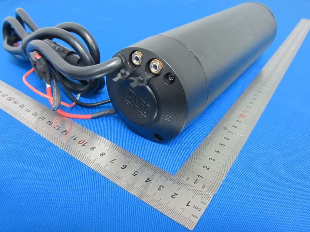
2AAOY-MUDHSB
Oct 31, 2015Bluetooth Speaker
Equipment Class
DSS - Part 15 Spread Spectrum Transmitter