2AB6UASL2Automatic Smart Door Lock
August Home Inc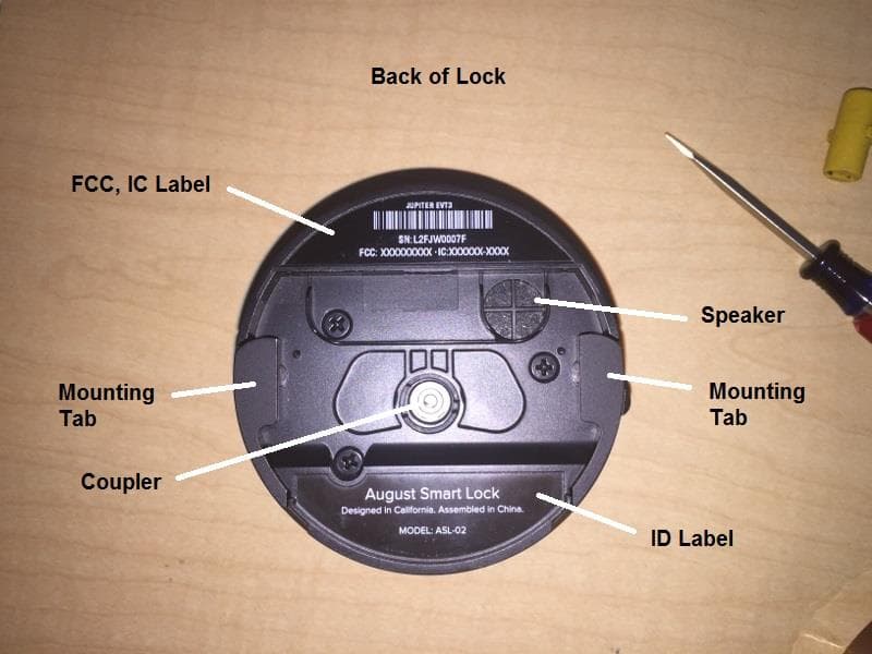
Click to zoom
Application Details
- Equipment Class
- DTS - Digital Transmission System
- Date of Grant
- Nov 10, 2015
- Application Purpose
- Original Equipment
- Date of Application
- Nov 10, 2015
- Equipment Note
- Automatic Smart Door Lock
- Frequency Range
- 2402.00000000 - 2480.00000000
- Company
- August Home Inc
- Country
- United States
Documents & Files
Document Text
Text extracted from the exhibit documents filed with the FCC. Open a document above to read the original.
Users Manual
1 Installation Guide Installation Guide2 Go to august.com/install to watch a video version of this installation guide. 3 Welcome! This guide will get you up and running with your August Smart Lock. Installation generally takes less than 15 minutes. If you have any trouble, please check our support section (august.com/support), contact our installer network (august.com/installers) or call 844-AUGUST1 (284-8781) for help. Installation Guide4 Preparation Make sure your existing deadbolt is compatible with the August Smart Lock. Only standard deadbolts are supported. Use our compatibility assistant to double- check: august.com/compatibility You will need a standard Phillips screwdriver. Tools needed Standard Deadbolt is mounted and operates independently of the door handle. Compatibility: YES 5 Alternately, we have a network of installers who can help with installation. august.com/installers Compatibility: NO Integrated Lock & Handle Handle and lock thumb- latch are both mounted together on a metal plate Mortise An integrated door handle and deadbolt in a single metal unit Rim Cylinder Mounted on the inside, on top of the door and door jamb Installation Guide6 1 August Smart Lock (4 AA Batteries Pre-installed) Package Contents 4 Adhesive Rubber Bumpers (Included Inside Envelope) 1 Adhesive Strip (Included Inside Envelope) 7 3 Mounting Plates 3 Adapters Installation Guide8 Installation Overview Before: After: Key Hole Deadbolt Tail Piece Mounting Plate Screws Tail Piece Adapter August Smart Lock & Face Plate Key Hole Deadbolt Tail Piece Thumb-latch Screws 1 2 3 4 5 6 7 1 1 2 3 4 5 2 3 4 5 Before Installation 9 1 2 3 4 5 6 7 After Installation Installation Guide10 Step 1: Prepare existing deadbolt. Affix the supplied adhesive strip over the key hole, securing it to the exterior side of your door. This should hold the key hole in place when you remove the thumb- latch on the inside of the door. On some doors, such as those with glossy paint, the included tape may not be strong enough. In this case you should apply additional stronger tape to ensure that the key hole stays in place. Use caution. Some types of tape, such as duct tape, may damage the paint on certain types of doors. 11 Installation Guide12 Step 2: Remove your existing thumb-latch. Position your thumb-latch so that you can unscrew the existing screws on your deadbolt. Remove the screws entirely from the deadbolt and keep them to assist in the next step. After removing the screws, be sure to unlock your deadbolt before removing the thumb-latch. Your thumb-latch may include an additional back plate underneath it. If so, remove the back plate. Use the back plate and the longer screws for the next step. B A 13 A B Installation Guide14 Step 3: Select the correct mounting plate and adapter. If you know the brand of your deadbolt, please select the correct mounting plate and adapter from the Compatibility Chart on the next page, and then go to Step 4 (page 18). If not, go to Step 3a (page 16) to find the correct mounting plate and adapter. If your tailpiece is in a vertical position when the door is unlocked, you will need to remove the keyhole and rotate it so the tailpiece is in a horizontal position before you install. 15 Standard Deadbolt Compatibility Chart BRAND MOUNTING PLATE ADAPTER Baldwin - Estate/Images* 1 Baldwin Reserve/Prestige 3 Defiant 2 Emtek 3 Kwikset* 3 Omnia** 1 Schlage*** 2 Weiser 2 Weslock 1 * Baldwin and Kwikset Deadbolts installed before 1997 have unique installation requirements, please contact us at 844-AUGUST1 (284-8781) and we will walk you through installation. ** Compatible only with non-mortise, standard Omnia deadbolts. *** Commercial grade Schlage B560 deadbolts require supplemental screws. If your Schlage screws are too short please contact us at [email protected] Installation Guide16 Step 3a: Select the correct mounting plate. Insert the existing screws in the thumb-latch to help you choose the correct mounting plate. If there was a back plate under your thumb-latch, insert the screws into this back plate instead of the thumb-latch. Slide the mounting plates onto the screws one at a time until you find a mounting plate that allows the screws to fit straight through the holes. B Having trouble selecting the right mounting plate? Try august.com/installation or call August customer support at 844-AUGUST1 (284-8781) A 17 BB A Compatibility: YESCompatibility: NO Installation Guide18 Step 4: Position the mounting plate. Remove the backing from the 4 rubber bumpers and place them on the back side of the mounting plate (the side that does not show a number). Rotate the mounting plate so the 4 rubber bumpers are between the mounting plate and the door. Remove the screws from the thumb-latch and use them to install the mounting plate over the existing deadbolt tail piece. Moderately tighten the screws until the mounting plate is settled against the door. Over-tightening can deform the mounting plate and interfere with the operation of the lock. B A C 19 CB A Back: YESFront: NO Installation Guide20 Step 5: Position adapter and align mounting plate. Remove the tape from the key hole, and use your key to turn your deadbolt to the fully unlocked position. If your lock was not in the Compatibility Chart, select the adapter that fits your tail piece. To do this, slide each adapter onto the tail piece. The correct adapter will have the small nub pointing up. Place the correct adapter onto the tail piece with the small nub pointing up. Tighten the screws until they are moderately tight. Do not over-tighten. Over-tighten- ing can deform the mounting plate and interfere with the operation of the lock. B C A 21 C Front View Deadbolt Tail Piece Adapter Alignment B A Installation Guide22 Step 6: Attach the August Smart Lock. Insert the adapter into the back of the August Smart Lock, then position the August Smart Lock with the August name badge at the top. Pull out both side wing latches. Slide the August Smart Lock over tail…
Text truncated - open the document above for the full version.
Cover Letter(s)
Receiver Federal Communications Commission Equipment Authorization Division, Application Processing Branch 7435 Oakland Mills Road Columbia, MD 21048 Subject: Request for Permanent Confidentiality FCC ID: 2AB6UASL2 To Whom It May Concern: In accordance with §0.457(d) and §0.459 of CFR 47 August Home Inc requests permanent confidentiality for the following items: 1.Schematic Diagram 2.Part List These items contain detailed system and equipment description and related information about the product which August Home Inc considers to be proprietary, confidential and a custom design which otherwise would not be released to the general public. Since this design is a basis from which future technological products will evolve, August Home Inc also feels that this information would be of benefit to its competitors, and that the disclosure of the information in these exhibits would give our competitors an unfair advantage in the market. Best Regards, On behalf of August Home Inc Joe Aranda [email protected] 760.828.2067 657 Bryant Street San Francisco, CA 94107
External Photos
August Home Inc. 09/21/2015 Model: ASL-02 FCC: 2AB6UASL2 IC: 12163A-ASL2 1 | P a g e ASL-02 External Photos
ID Label/Location Info
August Home Inc. 9/21/2015 Model: ASL-02 FCC: 2AB6UASL2 IC: 12163A-ASL2 ASL-02 Label Information The ASL-02 Labels are placed on the back of the lock as shown in the above photo. THIRD ANGLE PROJECTION ARTWORK LAYOUT, SCALE: 1:1 LABEL OUTLINE, SCALE: 1:1 25 4 0 1.6 4.2 7 ARTWORK LAYOUT, SCALE: 3:1 59.02 14.30 R37.60 LABEL OUTLINE, SCALE: 1:1 Note: Font: Proxima Nova -Condensed, 6 pt.1. Text Color: White2. See Artwork File for actual text/font.3. Part must be RoHS and REACH compliant.4. REVISIONS REV.DESCRIPTIONDATEBY 1Initial Release8/5/2015MC D C B A A B C D 1 2 3 4 5 6 7 8 7 6 5 4 3 2 1 SPECIFICATION SUBJECT TO CHANGE WITHOUT NOTICE. THE INFORMATION CONTAINED IN THIS DOCUMENT IS DEEMED TO BE ACCURATE AND CORRECT. HOWEVER, DUE TO THE MANUFACTURING PROCESS INVOLVED, SOME DETAILS OF THE FINAL PRODUCT MAY BE MODIFIED. UNLESS OTHERWISE SPECIFIED, DIMENSIONS ARE IN MM. DRAWN BY:DATE SIZE B DRAWING NO. REV SCALE: 1:1 SHEET 1 OF 1 DO NOT SCALE DRAWING MATERIAL:FINISH: Label, Unit, Serial, Jupiter M.CURRY 8/5/2015 50# Black Polyester 1090-00135 THIS DOCUMENT AND THE DATA DISCLOSED HEREIN OR HEREWITH IS NOT TO BE REPRODUCED, USED OR DISCLOSED IN WHOLE OR PART TO ANYONE WITHOUT THE PERMISSION OF AUGUST. 090-00135 Label, Unit, Serial, Jupiter 1.02 with barcode 2D CAD Filename PDMWorks File Rev Date & Time DECIMALS ANGLES .X .25 2 .XX .1 3D CAD Filename PDMWorks File Rev Configuration 090-00135 Label, Unit, Serial, Jupiter 1.02 8 DEFAULT TOLERANCES: THIRD ANGLE PROJECTION 54.40 R4.91 R37.60 39.88 5.88 17.16 LABEL OUTLINE, SCALE: 3:1 LABEL OUTLINE, SCALE: 1:1 0 5.5 8.3 12.5 ARTWORK LAYOUT, SCALE: 3:1 ARTWORK LAYOUT, SCALE: 1:1 Note: Font: Proxima Nova1. Text Color: White2. See Artwork File for actual text/font.3. Part must be RoHS and REACH compliant.4. REVISIONS REV.DESCRIPTIONDATEBY 3Initial Drawing Release. Change model number to ASL-02.8/6/2015MC D C B A A B C D 1 2 3 4 5 6 7 8 7 6 5 4 3 2 1 SPECIFICATION SUBJECT TO CHANGE WITHOUT NOTICE. THE INFORMATION CONTAINED IN THIS DOCUMENT IS DEEMED TO BE ACCURATE AND CORRECT. HOWEVER, DUE TO THE MANUFACTURING PROCESS INVOLVED, SOME DETAILS OF THE FINAL PRODUCT MAY BE MODIFIED. UNLESS OTHERWISE SPECIFIED, DIMENSIONS ARE IN MM. DRAWN BY:DATE SIZE B DRAWING NO. REV SCALE: 1:1 SHEET 1 OF 1 DO NOT SCALE DRAWING MATERIAL:FINISH: Label, Unit, Company, Jupiter M.CURRY 8/5/2015 PS 201B, Black 0.1mm thick NA 3090-00087 THIS DOCUMENT AND THE DATA DISCLOSED HEREIN OR HEREWITH IS NOT TO BE REPRODUCED, USED OR DISCLOSED IN WHOLE OR PART TO ANYONE WITHOUT THE PERMISSION OF AUGUST. 090-00087 Label, Unit, Company, Jupiter 3 Default 2D CAD Filename PDMWorks File Rev Date & Time DECIMALS ANGLES .X .25 2 .XX .1 3D CAD Filename PDMWorks File Rev Configuration 090-00087 Label, Unit, Company, Jupiter 3 8 DEFAULT TOLERANCES:
Test Report
FCC Recognized A2LA Accredited IC recognized # 3462E-1 CETECOM Inc. 6370 Nancy Ridge Drive Suite 101 San Diego, CA 92121 U.S.A. Phone: + 1 (858) 362 2400 Fax: + 1 (858) 587 4809 E-mail: [email protected] http://www.cetecom.com CETECOM Inc. is a Delaware Corporation with Corporation number: 2905571 V5.0 2015-10-27 © Copyright by CETECOM FCC / IC Test Report FOR: August Home Model Name: ASL-02 Product Description: Bluetooth (Low Energy) FCC ID: 2AB6UASL2 IC ID: 12163A-ASL2 Per: 47 CFR Part 15.247 (DTS) RSS-247 Issue 1 (DTSs) & RSS-Gen Issue 4 REPORT #: EMC_AUGUH_003_15001_15.247_DTS_BTLE_v1.3 DATE: 2015-11-11 Test Report #: EMC-AUGUH_003_15001_15.247_DTS_BTLE_v1.3 FCC ID: 2AB6UASL2 Date of Report 2015-11-11 Page 2 of 44 IC ID: 12163A-ASL2 TABLE OF CONTENTS 1 ASSESSMENT .............................................................................................................................................................. 4 2 ADMINISTRATIVE DATA ............................................................................................................................................... 5 2.1 IDENTIFICATION OF THE TESTING LABORATORY ISSUING THE EMC TEST REPORT ........................................................................... 5 2.2 IDENTIFICATION OF THE CLIENT ............................................................................................................................................. 5 2.3 IDENTIFICATION OF THE MANUFACTURER ................................................................................................................................. 5 3 EQUIPMENT UNDER TEST (EUT) ................................................................................................................................... 6 3.1 EUT SPECIFICATIONS ......................................................................................................................................................... 6 3.2 EUT SAMPLE DETAILS ......................................................................................................................................................... 7 3.3 ACCESSORY EQUIPMENT (AE) DETAILS ................................................................................................................................... 7 3.1 TEST SAMPLE CONFIGURATION ............................................................................................................................................. 7 4 SUBJECT OF INVESTIGATION ...................................................................................................................................... 8 5 MEASUREMENT RESULTS SUMMARY .......................................................................................................................... 9 6 MEASUREMENT UNCERTAINTY.................................................................................................................................. 10 7 ENVIRONMENTAL CONDITIONS DURING TESTING: ................................................................................................... 10 8 DATES OF TESTING: .................................................................................................................................................. 10 9 MEASUREMENT PROCEDURES .................................................................................................................................. 11 9.1 RADIATED MEASUREMENT .................................................................................................................................................. 11 9.2 SAMPLE CALCULATIONS FOR FIELD STRENGTH MEASUREMENTS ................................................................................................ 13 9.3 POWER LINE CONDUCTED MEASUREMENT PROCEDURE .......................................................................................................... 13 9.4 RF CONDUCTED MEASUREMENT PROCEDURE ....................................................................................................................... 14 10 MAXIMUM PEAK CONDUCTED OUTPUT POWER ...................................................................................................... 15 10.1 MEASUREMENT ACCORDING TO FCC KDB 558074 D01 V03R03 ...................................................................................... 15 10.2 LIMITS: ...................................................................................................................................................................... 15 10.3 TEST CONDITIONS AND SETUP: ........................................................................................................................................ 15 10.4 MEASUREMENT RESULT: ............................................................................................................................................... 15 10.5 MEASUREMENT PLOTS: ................................................................................................................................................ 16 11 POWER SPECTRAL DENSITY ...................................................................................................................................... 19 11.1 MEASUREMENT ACCORDING TO FCC KDB 558074 D01 V03R03 ...................................................................................... 19 11.2 LIMITS: §15.247 & RSS-247 ....................................................................................................................................... 19 11.3 TEST CONDITIONS AND SETUP: ........................................................................................................................................ 19 11.4 MEASUREMENT RESULT: ............................................................................................................................................... 19 11.5 MEASUREMENT PLOTS: ...........................................................................…
Text truncated - open the document above for the full version.
Test Setup Photos
FCC Recognized A2LA Accredited IC recognized # 3462E-1 CETECOM Inc. 6370 Nancy Ridge Drive Suite 101 San Diego, CA 92121 U.S.A. Phone: + 1 (858) 362 2400 Fax: + 1 (858) 587 4809 E-mail: [email protected] http://www.cetecom.com CETECOM Inc. is a Delaware Corporation with Corporation number: 2905571 V5.0 2015-10-27 © Copyright by CETECOM FCC / IC Test Report FOR: August Home Model Name: ASL-02 Product Description: Bluetooth (Low Energy) FCC ID: 2AB6UASL2 IC ID: 12163A-ASL2 REPORT #: EMC_AUGUH_003_15001_TEST_SETUP_PHOTOS DATE: 2015-11-11 Test Report #: EMC-AUGUH_003_15001_TEST_SETUP_PHOTOS FCC ID: 2AB6UASL2 Date of Report 2015-11-03 Page 2 of 5 IC ID: 12163A-ASL2 1 Setup Pictures 1.1 Conducted measurements setup 1.2 Radiated measurement setup below 30MHz Test Report #: EMC-AUGUH_003_15001_TEST_SETUP_PHOTOS FCC ID: 2AB6UASL2 Date of Report 2015-11-03 Page 3 of 5 IC ID: 12163A-ASL2 1.3 Radiated measurement setup between 30MHz and 1GHz 1.4 Radiated measurements setup above 1GHz Test Report #: EMC-AUGUH_003_15001_TEST_SETUP_PHOTOS FCC ID: 2AB6UASL2 Date of Report 2015-11-03 Page 4 of 5 IC ID: 12163A-ASL2 Test Report #: EMC-AUGUH_003_15001_TEST_SETUP_PHOTOS FCC ID: 2AB6UASL2 Date of Report 2015-11-03 Page 5 of 5 IC ID: 12163A-ASL2 2 EUT pictures
Contact Information
Applicant
Aaron Treger(Director, Hardware Engineering)
Test Firm
CETECOM Inc.Meinolf Glunz
[email protected]408-586-6301
Technical Specifications
| # | Rule Parts | Frequency Range | Power Output |
|---|---|---|---|
| 1 | 15C | 2.40 GHz - 2.48 GHz | 400.00 µW |
Other Applications from August Home Inc

2AB6U-ASL08
Sep 02, 2023August Smart Lock
Equipment Class
DTS - Digital Transmission System
2AB6UASL05-5G
Dec 08, 2022August WiFi Smart Lock
Equipment Class
DTS - Digital Transmission System
2AB6UABR1
Aug 25, 2015Smart Doorbell with 802.11a/b/g/n and Bluetooth 4.0
Equipment Class
DTS - Digital Transmission System
2AB6UAKR1
Aug 20, 2015Entry Pad with Bluetooth 4.1
Equipment Class
DTS - Digital Transmission System
2AB6UACR1
Jan 05, 2015August Connect
Equipment Class
DTS - Digital Transmission System