2ACDEQP100WOFeature Phone
Cubix Latin America, LLC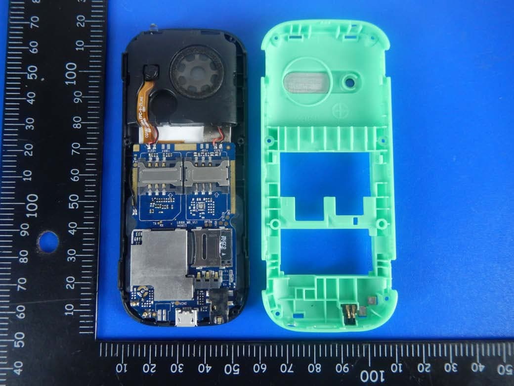
Click to zoom
Application Details
- Equipment Class
- DSS - Part 15 Spread Spectrum Transmitter
- Date of Grant
- Apr 21, 2015
- Application Purpose
- Original Equipment
- Date of Application
- Apr 21, 2015
- Equipment Note
- Feature Phone
- Frequency Range
- 2402.00000000 - 2480.00000000
- Company
- Cubix Latin America, LLC
- Country
- United States
Documents & Files
Document Text
Text extracted from the exhibit documents filed with the FCC. Open a document above to read the original.
Users Manual
mobility .com User Manual 2 User Manual Introduction 1. CHAPTER 1 • Basic Information 1.1 Brief introduction 2. CHAPTER 2 • Before Use 2.1. Name and explanation of each part 2.1.1 Appearance key map 2.1.2. Description of the standby pictures 2.1.3. Description of keys 2.2. Install SIM card and memory card 2.2.1. SIM card 2.2.2. Memory card 2.3. Battery 2.3.1. Install the battery 2.3.2. Charging 2.4. Security password 3. CHAPTER 3 • Quick User Guide 3.1. Dial a call 3.2. Reject a call 3.3. Receive a call 3.4. End a call 3.5. Emergency services 3.6. Dialed/Missed/Received/Rejected calls 3.7. Call forward 3.8. Call waiting 3.9. Call barring 3.10. Power off the phone 3.11. TF-flash card 4. CHAPTER 4 • Function Menu 4.1. Contacts 4.2. Message 4.3. Call logs 4.4. Settings 4.5. Naide zone 4.6. Multimedia 4.7. Tools 4.8. Profiles 4.9. Internet 5. CHAPTER 5 • Text Input 6. CHAPTER 6 • Care and Maintenance 3 Infinit yP1 CHAPTER 1 Basic Information 1.1. Brief Introduction Thanks for selecting Your QUO Infinity P1 colour screen GSM/GPRS digital mobile Phone. Through reading this manual, you can fully understand how to use your mobile Phone, appreciate its complete function and simple operating method. The mobile Phone is designed and aimed at the GSM/GPRS network environment and is a two Subscriber Identity Module (SIM) standby phone. You can`t call the other SIM card when one SIM card is in a phone. Besides basic call functions, the mobile Phone also provides many kinds of practical functions, such as Caller ID, scene mode, message, audio and video functions, camera and video, alarm clock, calculator, STK, time and date, auto power-on and shut-down that is convenient for your work and leisure activities. In addition the mobile Phone adopts a personalized human-computer interface design and its total functions can meet your different requirements. The mobile Phone meets the GSM/GPRS criteria and has obtained the certification of the relevant competent authority. The manufacturing company reserves the rights to revise the contents of this manual without prior notice. CHAPTER 2 Before Use 2.1. Name and Explanation of Each Part 2.1.1 Appearance key map 2.1.2. Description of the standby pictures Right soft Key Left soft Key OK Key End Key Navigation Key Dial Key 4 User Manual keysFunction Righ soft key-Left soft key. 1. Execute functions that the left-down/right-down corner indicator shows. 2. In the standby mode, press Left Soft key to access Menu, Right Soft key to access Contacts. Navigation key Traverse text left, right, up or down by depressing the navigation key in the relevant position. By depressing the center button the selected function is activated. Dial key1. Press this key to dial or receive incoming calls. 2. When in the standby mode, press this key to access Call Log. (Previously dialed calls) Network signal strength: The larger quantity of stripes displayed, the stronger the signal is. When SIM card (1) Is inserted in card slot 1, the standby screen (shown in yellow) will show the icon (1). Network signal strength: The larger quantity of stripes displayed, the stronger the signal is. When SIM card (2) is inserted in card slot 2, the standby screen (shown in yellow) will show the icon (2). Battery strength: The strength remaining in the battery is depicted by the bars shown in the battery icon. Normal mode: When the phone is in normal mode, the standby screen will show the depicted icon on the left. Silent mode: When the phone is in silent mode, the standby screen will show the depicted icon on the left. Meeting mode: When the phone is in meeting mode, the standby screen will show the depicted icon on the left. Indoor mode: When the phone is in Indoor mode, the standby screen will show the icon depicted on the left. Outdoor mode: NO icon will be displayed when the phone is set in the Outdoor mode. 2.1.3. Description of Keys: 5 Infinit yP1 OK key1. In the dial panel mode, press this key to show or hide dial panel. 2. A long press of this key (in standby interface) will turn on/off the Torch light. End key 1. Mainly used as power on/off. 2. Press to return to standby screen in any interface. 3. End calls or reject incoming calls. Number keyIt is used to dial and input numbers or characters. Press and hold Number key 1 or 2 to get through the preset voice inbox. * KeyOn the standby interface, input *; after inputting tel- ephone number, if you want to input extension number, press the asterisk key (*) twice, after the display screen shows “+”, input your extension number. #Key1. In text editing interface, press “#” key to switch text to the input method. 2. On the standby interface Press and hold “#” key to transfer to the Normal/Silent/Meeting profile. 2.2. INSTALL SIM CARD AND MEMORY CARD 2.2.1. SIM Card Before using the phone, you must insert your valid SIM (Subscriber Identity Module) cards in the phone. SIM cards 1 and 2 shall be obtained from the relevant preferred network providers. (It is recommended that the SIM Cards being installed in the device shall be obtained from differing network providers) When you subscribe to a cellular network, you will receive a plug-in SIM card complete with your subscription details which will include your Personal Identity Number (PIN) and Personal Unlock Number (PUK). Do not bend or damage your SIM card. Avoid exposing your SIM card to static electricity, water or dirt. Tips: Face the gold color contact point of the SIM card towards the cell phone and push the SIM card into the slot and secure 2.2.2. Memory Card Fit the TF card in place in the device in accordance with the peripheral shape shown on the device. Note: If the device does not read the memory card, please check if the card is correctly secured in the phone. 2.3. BATTERY 2.3.1 Install the Battery • Take off the rear cover of the mobile phone. 6 User Manual • Place the end of the battery with its gold contacts in line with the battery connector of the phone. • Then gently press the battery…
Text truncated - open the document above for the full version.
Cover Letter(s)
Differences Description We Cubix Latin America, LLC state: Product: Feature Phone Model Name: QP-100-WO;QP-100-BB; QP-100-BG; QP-100-BR; QP-100-BK; QP-100-BP; QP-100-BO; QP-100-BY; Trade Name: QUO FCC ID: 2ACDEQP100WO The electrical circuit design, layout, components used and internal wiring for above models are identical, only the model name is different. Signatory Date 2015-3-25 Signature Name: ELIAHU SIBONI Title: Commercial Director Company: Cubix Latin America, LLC Address: 2841 NW 107th Ave, Doral Florida, United States
Cover Letter(s)
SCS-F18: Project and Product Certification Representative Authorization Letter Page 1 of 2Rev 5.0 775 Montague Expressway Milpitas, CA 95035 Tel: 408-526-1188 Fax: 408-526-1088 Email: [email protected] Project and Product Certification Representative Authorization Letter Reason for Amendment (current / obsolete) Revision History Approved Date From To Initial Release (obsolete) 1.0 1.0 Nov-14-2006 Revised wording (obsolete) 1.0 2.0 Sept–25-2007 Updated company template (obsolete) 2.0 3.0 Jan-31-2012 Updated letter information (obsolete) 3.0 4.0 May-23-2014 Added FCC ID field (current) 4.0 5.0 Sept 16 2014 SCS-F18: Project and Product Certification Representative Authorization Letter Page 2 of 2Rev 5.0 Cubix Latin America, LLC 2015.3.18 To: SIEMIC, INC. 775 Montague Expressway, Milpitas, CA 95035 USA Dear Sir/Madam, Re: Product Certification Representative Authorization Letter We, Cubix Latin America, LLC hereby authorize SIEMIC, Inc. to act as a Certification Body for certifying for the following project(s): (Product description, model name): Product description: Feature Phone model name: QP-100-WO; QP-100-BB; QP-100-BG; QP-100-BR;QP-100- BK; QP-100-BP; QP-100-BO;QP-100-BY FCC ID: 2ACDEQP100WO Sincerely, Client’s signature : ELIAHU SIBONI Client’s name / title: Commercial Director Applicant company:Cubix Latin America, LLC address: 2841 NW 107th Ave, Doral Florida, United States
ID Label/Location Info
Label Feature Phone Model name: QP-100-WO Brand name: QUO FCC ID: 2ACDEQP100WO This device complies with part 15 of the FCC Rules. Operation is subject to the following two conditions: (1) This device may not cause harmful interference, and (2) this device must accept any interference received, including interference that may cause undesired operation. label
Internal Photos
BT ANTENNA GSM ANTENNA 3.72CM 4.86CM 2.54CM
Internal Photos
APPENDIX-PHOTOGRAPHS OF EUT CONSTRUCTIONAL DETAILS Photo 1 Photo 2 BT ANTENNA GSM ANTENNA Photo 3 Photo 4 Photo 5 Photo 6
RF Exposure Info
FCC ID : 2ACDEQP100WO RF EXPOSURE EVALUATION METHOD SAR Test Exclusion Thresholds for 100 MHz – 6 GHz and ≤ 50 mm Approximate SAR Test Exclusion Power Thresholds at Selected Frequencies and Test Separation Distances are illustrated in the following Table. The 1-g and 10-g SAR test exclusion thresholds for 100 MHz to 6 GHz at test separation distances ≤ 50 mm are determined by: [(max. power of channel, including tune-up tolerance, mW)/(min. test separation distance, mm)] · [√f(GHz)] ≤ 3.0 for 1-g SAR and ≤ 7.5 for 10-g extremity SAR,where f(GHz) is the RF channel transmit frequency in GHz Power and distance are rounded to the nearest mW and mm before calculation The result is rounded to one decimal place for comparison The test exclusions are applicable only when the minimum test separation distance is ≤ 50 mm and for transmission frequencies between 100 MHz and 6 GHz. When the minimum test separation distance is < 5 mm, a distance of 5 mm is applied to determine SAR test exclusion. FCC ID : 2ACDEQP100WO Maximum measured transmitter power. BT The worst case frequency Maximum Peak Conducted Output Power Tune up tolerance Max Antenna Gain GHz dBm dBm dBi 2.402 6.378 5.5±1 0 2.441 6.017 5.5±1 0 2.480 5.447 5.5±1 0 Remark: The best case gain of the antenna is 0dBi. 0dBi logarithmic terms convert to numeric result is nearly 1 (2.402GHz) -6.5dbm=4.4668mw (2.441GHz) -6.5dbm=4.4668mw (2.480GHz) -6.5dbm=4.4668mw BT: [(max. power of channel, including tune-up tolerance, mW)/(min. test separation distance,mm)] · [√f(GHz)]= 4.4668/5*√2.402=1.3846≤3.0 [(mid. power of channel, including tune-up tolerance, mW)/(min. test separation distance,mm)] · [√f(GHz)]= 4.4668/5*√2.441=1.3956≤3.0 [(min. power of channel, including tune-up tolerance, mW)/(min. test separation distance,mm)] · [√f(GHz)]= 4.4668/5*√2.480=1.4069≤3.0 Threshold at which no SAR required is 1.4069 ≤ 3.0 for 1-g SAR, Separation distance is 5mm. Conclusion: No SAR is required.
Test Report
Any reproduction of this document must be done in full. No single part of this document may be reproduced without permission from STS, All Test Data Presented in this report is only applicable to presented Test sample. Shenzhen STS Test Services Co., Ltd. 1/F, Building B, Zhuoke Science Park, Chongqing Road, Fuyong, Baoan District, Shenzhen, China TEL: +86-755 3688 6288 FAX: +86-755 3688 6277 E-mail:[email protected] FCC TEST REPORT Report No: STS1503054F02 Issued for Cubix Latin America, LLC 2841 NW 107th Ave,Doral Florida,United States Product Name: Feature Phone Brand Name: QUO Model No.: QP-100-WO Series Model: QP-100-BB; QP-100-BG; QP-100-BR; QP-100-BK; QP-100-BP; QP-100-BO; QP-100-BY; FCC ID: 2ACDEQP100WO Test Standard: FCC Part 15.247 S T L A B S Page 2 of 69 Report No.: STS1503054F02 TEST RESULT CERTIFICATION Applicant’s name ................. : Cubix Latin America, LLC Address ................................. : 2841 NW 107th Ave,Doral Florida,United States Manufacture's Name ............ : KBX GROUP Address ................................. : Avenida 1ra, Calle B y C manzana 58, France Field Colon Panama Product description Product name ........................... : Feature Phone Band name ................................ : QUO Model and/or type reference ............................. : QP-100-WO Ratings ................................... DC 5V/0.5A Standards ............................. : FCC Part 15.247 Test procedure ............................... : ANSI C63.10-2013 This device described above has been tested by STS, and the test results show that the equipment under test (EUT) is in compliance with the FCC requirements. And it is applicable only to the tested sample identified in the report. This report shall not be reproduced except in full, without the written approval of STS, this document may be altered or revised by STS, personal only, and shall be noted in the revision of the document. Date of Test ........................................... : Date (s) of performance of tests ............. : 15 Mar. 2015 ~22 Mar. 2015 Date of Issue.......................................... : 23 Mar. 2015 Test Result ............................................. : Pass Testing Engineer : (Jin Ming) Report writing : (Sunny zheng) Authorized Signatory : (Bovey Yang) Page 3 of 69 Report No.: STS1503054F02 Table of Contents Page 1. SUMMARY OF TEST RESULTS 5 1.1 TEST FACILITY 6 1.2 MEASUREMENT UNCERTAINTY 6 2. GENERAL INFORMATION 7 2.1 GENERAL DESCRIPTION OF EUT 7 2.2 DESCRIPTION OF TEST MODES 9 2.3 TABLE OF PARAMETERS OF TEXT SOFTWARE SETTING 9 2.4 BLOCK DIGRAM SHOWING THE CONFIGURATION OF SYSTEM TESTED 10 2.5 DESCRIPTION OF SUPPORT UNITS 11 2.6 EQUIPMENTS LIST FOR ALL TEST ITEMS 12 3. EMC EMISSION TEST 13 3.1 CONDUCTED EMISSION MEASUREMENT 13 3.1.1 POWER LINE CONDUCTED EMISSION LIMITS 13 3.1.2 TEST PROCEDURE 14 3.1.3 TEST SETUP 14 3.1.4 EUT OPERATING CONDITIONS 14 3.1.5 TEST RESULTS 15 3.2 RADIATED EMISSION MEASUREMENT 17 3.2.1 RADIATED EMISSION LIMITS 17 3.2.2 TEST PROCEDURE 18 3.2.3 DEVIATION FROM TEST STANDARD 18 3.2.4 TEST SETUP 19 3.2.5 EUT OPERATING CONDITIONS 20 3.2.6 TEST RESULTS 21 4. CONDUCTED SPURIOUS EMISSIONS 27 4.1 REQUIREMENT 27 4.2 TEST PROCEDURE 27 4.3 TEST SETUP 27 4.4 EUT OPERATION CONDITIONS 27 4.5 TEST RESULTS 28 5. NUMBER OF HOPPING CHANNEL 37 5.1 APPLIED PROCEDURES / LIMIT 37 5.2 TEST PROCEDURE 37 5.3 TEST SETUP 37 5.4 EUT OPERATION CONDITIONS 37 Page 4 of 69 Report No.: STS1503054F02 Table of Contents Page 5.5 TEST RESULTS 38 6. AVERAGE TIME OF OCCUPANCY 39 6.1 APPLIED PROCEDURES / LIMIT 39 6.2 TEST PROCEDURE 39 6.3 TEST SETUP 39 6.4 EUT OPERATION CONDITIONS 39 6.5 TEST RESULTS 40 7. HOPPING CHANNEL SEPARATION MEASUREMEN 46 7.1 APPLIED PROCEDURES / LIMIT 46 7.2 TEST PROCEDURE 46 7.3 TEST SETUP 46 7.4 EUT OPERATION CONDITIONS 46 7.5 TEST RESULTS 47 8. BANDWIDTH TEST 53 8.1 APPLIED PROCEDURES / LIMIT 53 8.2 TEST PROCEDURE 53 8.3 TEST SETUP 53 8.4 EUT OPERATION CONDITIONS 53 8.5 TEST RESULTS 54 9. PEAK OUTPUT POWER TEST 60 9.1 APPLIED PROCEDURES / LIMIT 60 9.2 TEST PROCEDURE 60 9.3 TEST SETUP 60 9.4 EUT OPERATION CONDITIONS 60 9.5 TEST RESULTS 61 10. ANTENNA REQUIREMENT 67 10.1 STANDARD REQUIREMENT 67 10.2 EUT ANTENNA 67 APPENDIX- PHOTOS OF TEST SETUP 68 Page 5 of 69 Report No.: STS1503054F02 1. SUMMARY OF TEST RESULTS Test procedures according to the technical standards: FCC Part15 (15.247) , Subpart C Standard Section Test Item Judgment Remark 15.207 Conducted Emission PASS 15.247(a)(1) Hopping Channel Separation PASS 15.247(b)(1) Peak Output Power PASS 15.247(c) Radiated Spurious Emission PASS 15.247(d) Conducted Spurious Emission PASS 15.247(a)(iii) Number of Hopping Frequency PASS 15.247(a)(iii) Dwell Time PASS 15.247(a)(1) Bandwidth PASS 15.205 Band Edge Emission PASS 15.203 Antenna Requirement PASS NOTE: (1)” N/A” denotes test is not applicable in this Test Report Page 6 of 69 Report No.: STS1503054F02 1.1 TEST FACILITY Shenzhen STS Test Services Co., Ltd. Add. : 1/F, Building 2, Zhuoke Science Park, Chongqing Road, Fuyong, Baoan District, Shenzhen, China. FCC Registration No.: 842334; IC Registration No.: 12108A-1 1.2 MEASUREMENT UNCERTAINTY The reported uncertainty of measurement y ± U,where expended uncertainty U is based on a standard uncertainty multiplied by a coverage factor of k=2,providing a level of confidence of approximately 95 %。 No. Item Uncertainty 1 Conducted Emission Test ±3.18dB 2 RF power,conducted ±0.16dB 3 Spurious emissions,conducted ±0.21dB 4 All emissions,radiated(<1G) ±4.68dB 5 All emissions,radiated(>1G) ±4.71dB 6 Temperature ±0.5°C 7 Humidity ±2% Page 7 of 69 Report No.: STS1503054F02 2. GENERAL INFORMATION 2.1 GENERAL DESCRIPTION OF EUT Equipment Feature Phone Trade Name QUO Model Name QP-100-WO Serial Model QP-100-BB; QP-100-BG; QP-100-BR; QP-100-BK; QP-100-BP; QP-100-BO; QP-100-BY; Model Difference Only difference in mode name Channel List Please refer to the Note 2. Bluetooth Frequency:2402 – 2480 MHz Modulation: GFSK(1Mbps), π/4-…
Text truncated - open the document above for the full version.
Test Setup Photos
DSS setup photo DSS conduction DSS radiation L DSS radiation H DSS RF conduction test photos DSS High and low temperature test photos
Contact Information
Applicant
ELIAHU SIBONI(Commercial Director)
Test Firm
Shenzhen STS Test Services Co., Ltd.Bovey Yang
Technical Specifications
| # | Rule Parts | Frequency Range | Power Output |
|---|---|---|---|
| 1 | 15C | 2.40 GHz - 2.48 GHz | 4.34 mW |
Other Applications from Cubix Latin America, LLC
2ACDEQSP500DBK
Apr 19, 2015Smart Phone
Equipment Class
DSS - Part 15 Spread Spectrum Transmitter
2ACDEMP3G-PQ5
Mar 31, 2015GSM and WCDMA Mobile Phone
Equipment Class
PCE - PCS Licensed Transmitter held to ear
2ACDE-QD-700II
Sep 19, 2014Tablet
Equipment Class
DXX - Part 15 Low Power Communication Device Transmitter
2ACDEQSPR-303BT
Aug 27, 2014Bluetooth Speaker
Equipment Class
DSS - Part 15 Spread Spectrum Transmitter
2ACDEQSPR-312BT
Aug 27, 2014Bluetooth Speaker
Equipment Class
DSS - Part 15 Spread Spectrum Transmitter