2ACS62RXReceiver of Surveyor Drone
ZEGO ELECTRONIC COMPANY LIMITED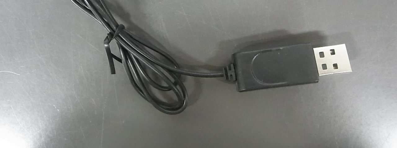
Click to zoom
Application Details
- Equipment Class
- DXX - Part 15 Low Power Communication Device Transmitter
- Date of Grant
- Aug 19, 2014
- Application Purpose
- Original Equipment
- Date of Application
- Aug 19, 2014
- Equipment Note
- Receiver of Surveyor Drone
- Frequency Range
- 2402.00000000 - 2475.00000000
- Country
- Hong Kong
Documents & Files
Document Text
Text extracted from the exhibit documents filed with the FCC. Open a document above to read the original.
Users Manual
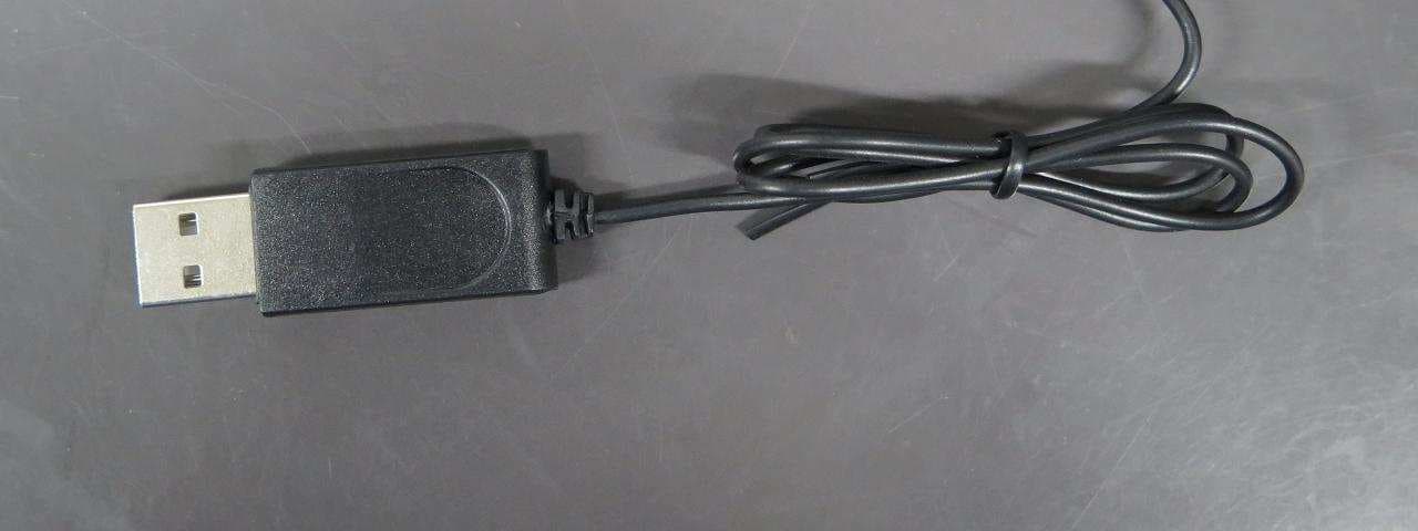
©2014 RadioShack Corporation. All rights reserved. RadioShack is a registered trademark used by RadioShack Corporation. 07A14 6001145 Printed in China Sur veyor Drone Install Batteries in the Transmitter 1. On the transmitter, set the ON/OFF switch to OFF. 2. Use a screwdriver to open the battery compartment. 3. Insert two AAA batteries (not included), matching the polarities marked inside. Use alkaline batteries for optimal performance. During play, if the transmitter’s LED flashes, replace the batteries. Age 14+ Get Ready to Fly 1. Open the drone battery compartment door and find the battery socket. 2. Plug the drone battery to the socket. The four LEDs (two in white in the front, two in green in the back) flash. 3. Insert the battery with its cable into the battery compartment. 4. Secure the compartment door. 5. Place the drone on level ground. 6. Switch on the transmitter. The transmitter’s LED lights. 7. Move the throttle all the way from the descend position to ascend and back to descend to pair the transmitter with the drone. The drone’s blades remain still during pairing. When paired, the drone’s LEDs stop flashing and remain on. Note: If pairing fails, switch off the drone and transmitter and repeat the steps above, or move locations to avoid interference. Fly Your Drone 1. After pairing, press the steering control to switch between high speed (double beep) and normal speed (single beep). 2. For beginners: With the drone on the ground, move the throttle forward to fly. For advanced users: Hold the transmitter with one hand, resting your thumb on the throttle. Then throw the drone about three meters away from you, and promptly move the throttle forward to fly. The drone adjusts itself automatically and flies stably. 3. To land your drone, slowly move the throttle backward to descend. Avoid moving the throttle too quickly, as that can stop the blades instantly and cause the drone to crash. 4. When you finish playing, disconnect and remove the drone battery and turn off the transmitter. We hope you enjoy your Surveyor Drone from RadioShack. Please read this user’s guide before setting up and using your drone. What’s Included • Surveyor Drone • Transmitter • USB Charging Cable • Spare Blades (4) • 3.7V Drone Battery • User’s Guide Charge the Drone Batter y Your drone uses a lithium polymer battery for power. 1. Hold the battery connector (NOT the cable) and carefully unplug the battery from the drone. 2. Use the USB charging cable to connect the battery to a USB power source, such as a laptop. The LED on the USB connector lights red during charging, and turns off when charging is complete. A full charge takes about 35 minutes. When the battery is fully charged, the drone can fly up to 5 minutes. 3. After charging, unplug the USB charging cable. Do not attempt to overcharge the battery. Caution: • Use only the supplied lithium battery. Using any other battery may damage the drone. • Only use the included USB charging cable to charge the drone battery. LED ON/OFF Steering • Move forward/ backward • Slide right/left • Switch between high and low speed Throttle • Speed up (ascend)/ slow down (descend) • Turn right/left • Play flip stunts 1 2 LED A A A A A A Camera Lens Front LEDs (white) Back LEDs (green) Rotor Blades (4) 6001145_UG_EN_072914.indd 17/30/2014 9:52:13 AM Perform Flip Stunts 1. Press and hold the throttle control. The transmitter beeps. 2. Move the steering control to perform flips: • Front flip: Move lever forward • Back flip: Move lever backward • Barrel roll: Move lever right or left 3. To exit stunt mode, release the throttle before moving the steering control. IMPORTANT: Make sure there is enough space for the drone to perform a flip. Avoid crashing on people or any object. Trim Your Drone Use the two trim pads to fine-tune your drone to avoid excess drift. Push the throttle forward and observe how the drone reacts. Forward/Reverse Movement Trim: If the drone tends to move forward, press the lower part on this pad; if it tends to move backward, press the upper part. Left/Right Slide Trim: If the drone tends to slide right, press the upper part on this pad; if it tends to slide left, press the lower part. Note: The transmitter sounds a short beep when you press any trim control. A long beep sounds when you reach maximum trim adjustment. Fly Safely • When flying outdoors, keep the drone away from power-lines, trees, weeds, and water. • When flying indoors, keep the drone away from walls, air conditioning, air vents, fans, breakable objects, and other obstacles. • Do not fly the drone near or at other people or animals. Use caution when flying, make sure people around you know that you are playing with the drone. • Keep eyes, hands, hair and loose clothing away from moving blades. • Fly the drone safely. If it crashes, the SD card may fall out and be lost. • Adult supervision is recommended at all times. CHOKING HAZARD! Small parts. Not for children under 3 years. Specif ications Power ..................2 × AAA batteries (transmitter) .....................3.7V lithium polymer battery (drone) Lens Resolution ......................................1080 × 720 Control Distance ....................................65 ft (20m) Specifications are subject to change and improvement without notice. Actual product may vary from the images found in this document. Troubleshooting Drone is not responding • Make sure the drone and transmitter are switched on and paired. When they are paired, the LEDs of the drone and transmitter are on. • The drone battery may be low. Charge the battery fully. (Refer to “Charge the Drone Battery“) • Transmitter battery may be low. Replace the batteries. • Make sure the drone is within the control range (65 ft./20m) and in line of sight. Drone dif f icult to control • The throttle control is very sensitive. Use small, fine movements of the throttle. • If you are a beginner, use the steering control to set to the normal speed mode. It is easier to control …
Text truncated - open the document above for the full version.
External Photos
External Photo
ID Label/Location Info
Label
Internal Photos
Internal Photo
Operational Description
Technical Description The equipment under test (EUT) is a 2.4GHz receiver operating at 2402 - 2475 MHz. It is powered by 3.7V rechargeable battery. When the receiver receives the radio, it will take corresponding actions Antenna Type: Coaxial shielded antenna RX FUNCTION: The functions of RX main ICs are mentioned as below. 1. Main Control is MCU for system. 2. POWER is rechargeable battery. 3. Motor takes corresponding action when receiving signal 4. 16M Cystal is crystal oscillator which provide 16MHz clock to 2.4G Module
Schematics
123456 A B C D 6 54321 D C B A RXD TXD C7 104 R1 10k C11 10uF C8 104 C1 222 SWIM RESET +3V3 RXD TXD 单片机 NRST 1 PA1/OSCIN 2 PA2/OSCOUT 3 PA3 7 PB7 9 PB6 10 PB5/SDA 11 PB4/SCL 12 PB3/TIM1_ETR/AIN3 13 PB2/TIM1_CH3N/AIN2 14 PB1/TIM1_CH2N/AIN1 15 PB0/TIM1_CH1N/AIN0 16 PC1/TIM1_CH1 18 PC2/TIM1_CH2 19 PC3/TIM1_CH3 20 PC4/TIM1_CH4 21 PC5/SPI_SCK 22 PC6/SPI_MOSI 23 PC7/SPI_MISO 24 PD0 25 PD1/SWIM 26 PD2/TIM2_CH3 27 PD3/TIM2_CH2/ADC_ETR 28 PD4/TIM2_CH1/BEEP 29 PD5/UART1_TX 30 PD6/UART1_RX 31 PD7/TIM1_CH4/TLI 32 PF4 8 PE5/SPI_NSS 17 VSS 4 VCAP 5 VDD 6 U1 ST105 SCK MOSI MISO SWIM 3.3V C8 104 BAT1 + C20 47UF B+ B 1 C 3 E 2 Q4 6206 C24 47UF C22 104 R31 1K B L R F 3.3V 3.3V R13 3.3K R12 3.3K CS_RF 3.3V R28 100K R29 47K B+ LV LV CE 1 CSN 2 SCK 3 MOSI 4 MISO 5 IRQ 6 VDD 7 VSS 8 XTALP 9 XTALN 10 VDDPA 11 RFP 12 RFN 13 VSS 14 VDD 15 IREF 16 VSS 17 VDD 18 CDVDD 19 VSS 20 U4BK2423 3.3V IRQ L2 4.7NH L18.2NH L3 3.9NH R30 1M C19 22P C18 22P C15 4.7P C162.2P C17 0.5P C4 104 Y1 16M R27 22K C14 333 ANT ANT R26 10K SCK MISO MOSI CS_RF CLKIN 1 NC 2 NC 3 NC 4 NC 5 AUX-DA 6 AUX-CL 7 VLOGIC 8 AD0 9 REGOUT 10 FSYNC 11 INT 12 VDD 13 NC 14 NC 15 NC 16 NC 17 GND 18 RESV 19 CPOUT 20 RESV 21 CLKOUT 22 SCL 23 SDA 24 U5 6050 3.3V B 1 C 3 E 2 Q55V L4 47UH C25 10UF C23 104 SDASCL C13 103 C9 104 C10 104 3.3V SDA SCL R11 3.3K R10 3.3K 3.3V 3.3V CS_G D1 5819 LED2 对打发射 R5 1K DD6 IR B 1 C 3 E 2 Q3 8050 R19 4.7R B+ 对打发射 DD3 R_LED R7 470R R6 470R C6 104 B+ M4 R24 10K R25 10K C5 104M3 F B C3 104 B+ M2 R22 10K R23 10K C2 104 M1 L R 红外接收 R3 1k DD2 R_LED B 1 C 3 E 2 Q1 8050 B+ LED2 DD4 R_LED R9 470R R8 470R R4 1k DD5 R_LED B 1 C 3 E 2 Q2 8050 B+ LED1 123 IR1 IR接收头 R18 10R C12 4.7UF 3.3V 红外接收 LED1 R16 1.5M R17 1.5M R21 750K 堵转1 R14 1.5M R15 1.5M R20 750K 堵转2 堵转1 堵转2 C27 22UF C11 10UF C26 10UF C21 104 Q8 2314 Q9 2314 Q6 2314Q7 2314
Test Report
TEST REPORT Report No. : AS0047564(4) Date : 18 Aug 2014 Tested by: Reviewed by: Mr. LEUNG Shu-kan, Ken Mr. WONG Lap-pong, Andrew Page 28 of 29 FCC ID: 2ACS62RX A7. Band Edge Lower edge (Peak measurement) Lower edge (Average measurement) TEST REPORT Report No. : AS0047564(4) Date : 18 Aug 2014 Tested by: Reviewed by: Mr. LEUNG Shu-kan, Ken Mr. WONG Lap-pong, Andrew Page 29 of 29 FCC ID: 2ACS62RX A7. Band Edge Upper edge (Peak measurement) Upper edge (Average measurement) ***** End of Report *****
Test Report
TEST REPORT Report No. : AS0047564(4) Date : 18 Aug 2014 For and on behalf of CMA Industrial Development Foundation Limited Authorized Signature : Page 1 of 29 Mr. WONG Lap-pong, Andrew Manager Electrical Division FCC ID: 2ACS62RX Application No. : LS025878(8) Applicant : Zego Electronic Company Limited (Shenzhen Yangri Electronic Ltd) Room 703, Kowloon Building, 555 Nathan Road, Kowloon, HK Sample Description : One(1) item of submitted sample stated to be Receiver of Surveyor Drone of Model No. 6001145 Sample registration No. : RS031557-001 Radio Frequency : 2402MHz – 2475 MHz Transceiver Rating : 3.7V rechargeable battery No. of submitted sample : Eight (8) set (s) Date Received : 25 Jul 2014, 15 Aug 2014 Test Period : 25 Jul 2014 to 15 Aug 2014. Test Requested : FCC Part 15 Certificate Test Method : 47 CFR Part 15 (10-1-12 Edition) ANSI C63.4 – 2009 Test Engineer : Mr. LEUNG Shu-kan, Ken Test Result : See attached sheet(s) from page 2 to 29. Conclusion : The submitted sample was found to comply with requirement of FCC Part 15 Subpart B and C. TEST REPORT Report No. : AS0047564(4) Date : 18 Aug 2014 Page 2 of 29 FCC ID: 2ACS62RX Table of Contents 1 General Information ................................................................................................................................... 3 1.1 General Description ............................................................................................................................ 3 1.2 Location of the test site ....................................................................................................................... 4 1.3 List of measuring equipment............................................................................................................... 5 1.4 Measurement Uncertainty ................................................................................................................... 6 2 Description of the radiated emission test ................................................................................................... 7 2.1 Test Procedure .................................................................................................................................... 7 2.2 Test Result .......................................................................................................................................... 8 2.3 Radiated Emission Measurement Data ............................................................................................... 9 3 Description of the Line-conducted Test ................................................................................................... 13 3.1 Test Procedure .................................................................................................................................. 13 3.2 Test Result ........................................................................................................................................ 13 3.3 Graph and Table of Conducted Emission Measurement Data .......................................................... 13 4 Photograph ...............................................................................................................................................14 4.1 Photographs of the Test Setup for Radiated Emission and Conducted Emission ............................. 14 4.2 Photographs of the External and Internal Configurations of the EUT.............................................. 14 5 Supplementary document......................................................................................................................... 15 5.1 Bandwidth ......................................................................................................................................... 15 5.2 Duty cycle ......................................................................................................................................... 15 5.3 Transmission time ............................................................................................................................. 15 5.4 Power Spectral Density..................................................................................................................... 15 5.5 Average on time ................................................................................................................................ 15 6 Appendices...............................................................................................................................................16 TEST REPORT Report No. : AS0047564(4) Date : 18 Aug 2014 Page 3 of 29 FCC ID: 2ACS62RX 1 General Information 1.1 General Description The equipment under test (EUT) is a receiver for helicopter. The EUT is power by 3.7V rechargeable battery. It operates at 2402MHz – 2475 MHz. When the receiver receives radio signal from transmitter, it will take corresponding actions. The brief circuit description is listed as follows: - U5 and its associated circuit act as MCU - U4 and its associated circuit act as RF circuit - Y1 and its associated circuit act as oscillator - Q1, Q2, Q3 and its associated circuit act as LED - M1, M2, M4, M4 and its associated circuit act as motor TEST REPORT Report No. : AS0047564(4) Date : 18 Aug 2014 Page 4 of 29 FCC ID: 2ACS62RX 1.2 Location of the test site FCC Registered Test Site Number: 552221 Radiated emissions measurements are investigated and taken pursuant to the procedures of ANSI C63.4 – 2009. A Semi-Anechoic Chamber Testing Site is set up for investigation and located at: Ground Floor, Yan Hing Centre, 9 – 13 Wong Chuk Yeung Street, Fo Tan, Shatin, New Territories, Hong Kong. Conducted emissions measurements are investigated and also taken pursuant to the procedures of ANSI C63.4 – 2009. A shielded room is located at : Ground Floor, Yan Hing Centre, 9 – 13 Wong Chuk Yeung Street, Fo Tan, Shatin, New Territories, Hong Kong. TEST REPORT Report No. : AS0047564(4) Date : 18 Aug 2014 Page 5 of 29 FCC ID: 2…
Text truncated - open the document above for the full version.
Test Setup Photos
Test Setup Photo Front view (30MHz – 1GHz) Rear view (30MHz – 1GHz) Front view (9kHz - 30MHz) Rear view (9kHz – 30MHz) Front view (1GHz – 25GHz) Rear view (1GHz – 25GHz) Conducted emission (Front view) Conducted emission (Back view) Conducted emission (Side view)
Contact Information
Applicant
JADE WANG(VICE-GENERAL MANAGER)
Test Firm
CMA Industrial Development Foundation LimitedJoey Kwok
[email protected]+852 2690 8255
Technical Specifications
| # | Rule Parts | Frequency Range | Power Output |
|---|---|---|---|
| 1 | 15C | 2.40 GHz - 2.48 GHz | - |
Other Applications from ZEGO ELECTRONIC COMPANY LIMITED
2ACS64RX
Aug 19, 2015Copter of Vektor Drone
Equipment Class
DXX - Part 15 Low Power Communication Device Transmitter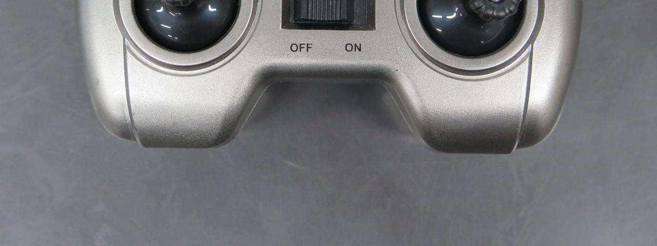
2ACS65TX
Aug 19, 2015Controller of Dominator Drone
Equipment Class
DXX - Part 15 Low Power Communication Device Transmitter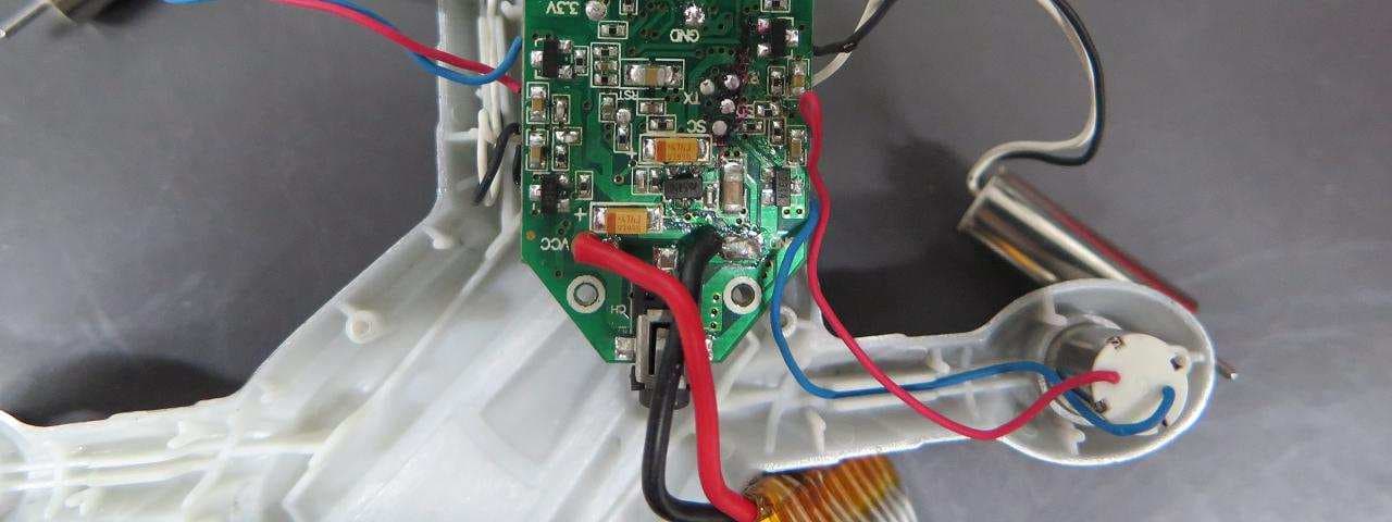
2ACS67RX
Aug 19, 2015Copter of Battle Drone
Equipment Class
DXX - Part 15 Low Power Communication Device Transmitter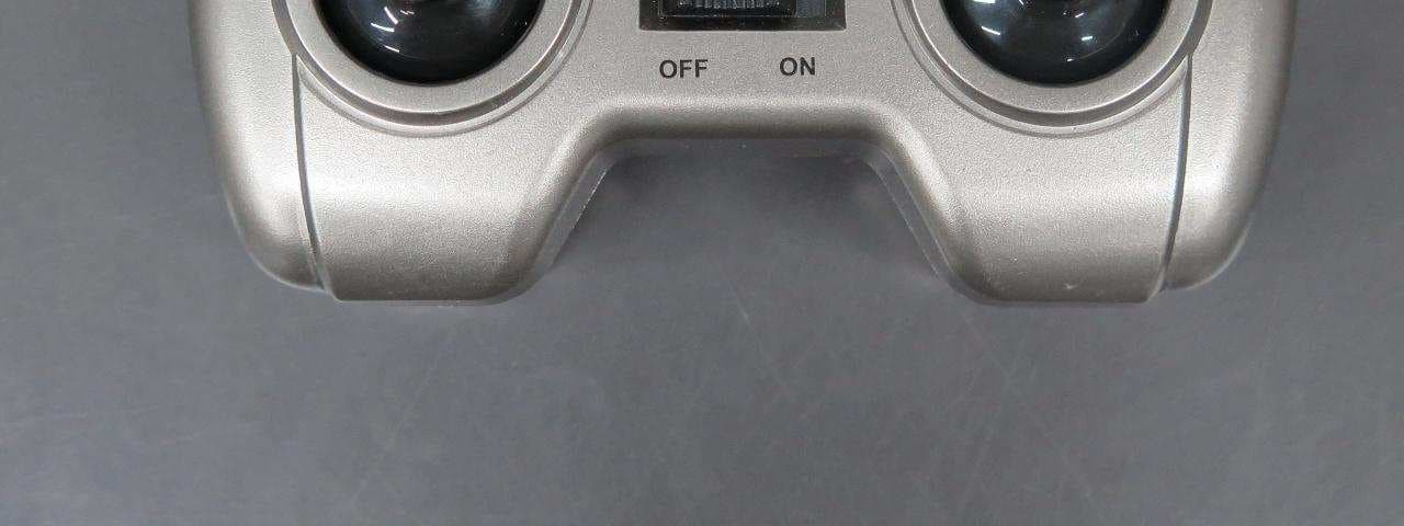
2ACS67TX
Aug 19, 2015Controlller of Battle Drone
Equipment Class
DXX - Part 15 Low Power Communication Device Transmitter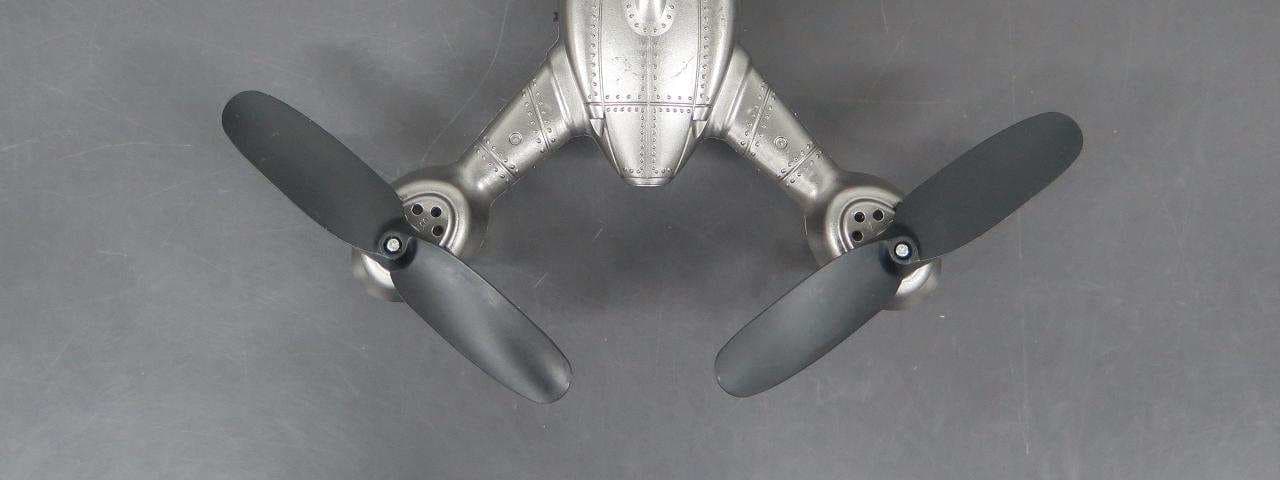
2ACS65RX
Aug 19, 2015Copter of Dominator Drone
Equipment Class
DXX - Part 15 Low Power Communication Device Transmitter