2AD9I-DL815Data Logger Vehicular Transceiver
DANLAW Inc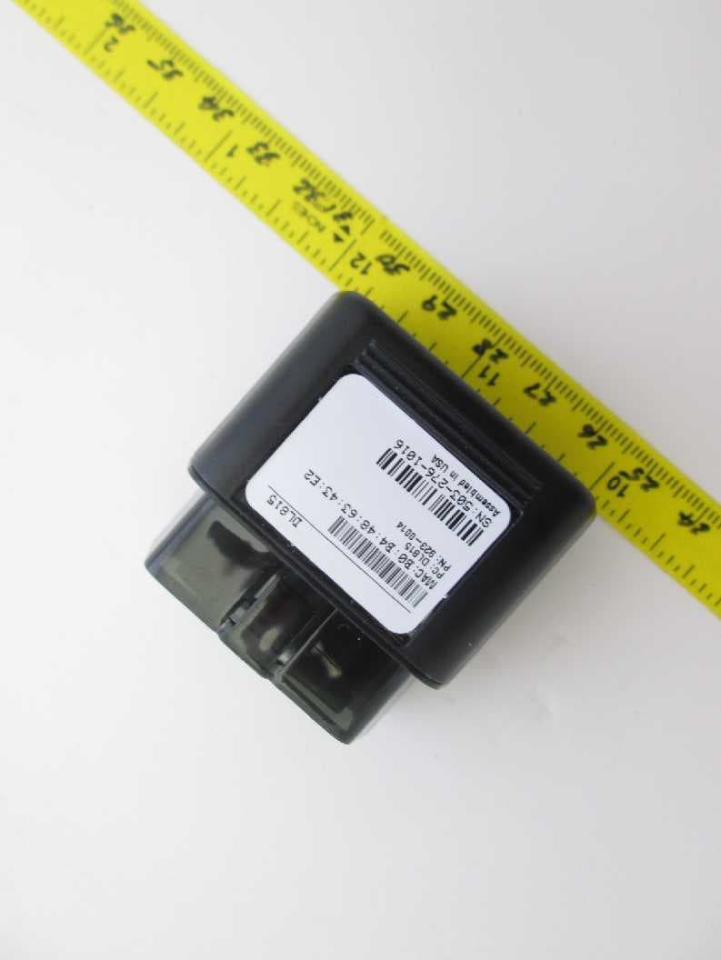
Click to zoom
Application Details
- Equipment Class
- DTS - Digital Transmission System
- Date of Grant
- Jun 10, 2015
- Application Purpose
- Original Equipment
- Date of Application
- Jun 10, 2015
- Equipment Note
- Data Logger Vehicular Transceiver
- Frequency Range
- 2402.00000000 - 2480.00000000
- Company
- DANLAW Inc
- Country
- United States
Documents & Files
Document Text
Text extracted from the exhibit documents filed with the FCC. Open a document above to read the original.
Users Manual
DANLAW DATA LOGGER DL-815 USER MANUAL Revision: Draft Revision date: 3/18/2015 1.1 Product Overview Danlaw’s Data Logger was developed to provide companies with an easy to install, wireless communication device for monitoring and logging vehicle network message data. The need for the DDL was driven by Danlaw’s own experience with Networked Automotive Electronics solution development, and perfected to provide our customers with the benefits of our experience. The Danlaw Data Logger provides: Support for all major passenger car & light truck protocols Simple plug-n-go via the vehicle’s OBDII connector OBD Vehicle Data logging with real-time data stamp Rugged, compact field-hardened design No external antenna connections needed Completely self contained Danlaw Data Logger – Vehicle Data Logger with Bluetooth Danlaw Data Logger - Advantage DL-860 Features: High Speed Data Upload – DDL has been demonstrated to significantly reduce the Data Upload time as compared to the speed of other wired and wireless OBDII interface solutions. Stand Alone Simplicity – Easy plug in and even easier to use. No external connections needed. Eliminates the need for costly power adapters, antenna connections and knowledgeable resources to install the module. Portability – The DDL has been designed to maximize in-the- field efficiency, light weight, robust, and compact design. Low Cost Solution – Low data transmission cost due to optimized data transmission, cost effective hardware – no maintenance and no batteries. Rugged Design – (-40C to +85C), IP 64 rated, it’s field ready. Flexible – Supports all major OEMs including: GM, Ford, DCX, Honda, Toyota, Nissan, BMW, Audi, Volvo and more. 1.2 Product Specifications Danlaw Data Logger - Specifications OPERATING VOLTAGE: 9 V DC to 24 V DC (Surge up to 32V) POWER CONSUMPTION: < 100 mA @ 12VDC (Data Upload) < 3 mA Average (during Sleep mode) TEMPERATURE RANGE: -40 C to +85 C (operating) HUMIDITY: 90% RH – non condensing CERTIFICATIONS: RoHS Compliant VEHICLE COMMUNICATION: Vehicle Protocol Support: GMLAN, FNOS, ISO-9141-2, SAE J1850 VPW, SAE J1850 PWM, ISO 14230-4, ISO 15765 (11bit CAN & 29bit CAN), SW CAN Vehicle Message Data: Time Stamped Event and Vehicle Message Bus Data Recording including: (All OEM Supported OBDII Data including: VIN, ODO, Time &Date, Vehicle Speed, module connect/disconnect events) PHYSICAL DIMENSIONS: Ultra Compact PACKAGING: Danlaw Data Logger Enclosure (IP 64 rated) INSTALLATION TIME: 10 Seconds NUMBER OF TRIPS: Unlimited DATA RECORDING INTERVAL: Selectable (1 Hz and up) FCC ID: 2AD9I-DL815 Model: DL815 IC: XXXXX-YYYYYYYY This device complies with Part 15 of the FCC Rules and with Industry Canada license- exempt RSS standard(s). Operation is subject to the following two conditions: (1) This device may not cause harmful interference, and (2) This device must accept any interference received, including interference that may cause undesired operation. Le présent appareil est conforme aux CNR d'Industrie Canada applicables aux appareils radio exempts de licence. L'exploitation est autorisée aux deux conditions suivantes : (1) l'appareil ne doit pas produire de brouillage, et (2) l'utilisateur de l'appareil doit accepter tout brouillage radioélectrique subi, même si le brouillage est susceptible d'en compromettre le fonctionnement. Note: Changes or modifications not expressively approved by the party responsible for compliance could void the user's authority to operate the equipment. 2.0 Installation Instructions 1. Locate the OBD connector: If you are not able to locate the OBD connector, please refer to the Vehicle User Manual 2. Install the DL-815 device by plugging it into the OBD connector 3.0 Revision History 3/19/2015 Draft Release
Cover Letter(s)
Willow Run Test Labs, LLC 8501 Beck Road, Building 2227 Belleville, Michigan 48111 USA Tel: (734) 252-9785 Fax: (734) 926-9785 e-mail: [email protected] Attn.:American Certification Body, Inc. 6731 Whittier Avenue Suite C110 McLean, VA 22101 Re:Certification for Danlaw Inc. DL815 Please find enclosed application materials for certification of Danlaw Inc. DL815. Note that portions of this submittal are filed Confidential. Current Variants: There is only a single variant of the EUT. Test samples were programmed into worst case on time, worst case emission bandwidth, and CW mode using a supplied PC interface. If there are any questions regarding the application or testing performed, please contact us at the above address or call (734) 252-9785, or e-mail [email protected]. Sincerely, Joseph D. Brunett Willow Run Test Labs, LLC 12
RF Exposure Info
RF Exposure / SAR / Health Hazard Statement Requirement: According to USA CFR 15 §1.1307 (b)(1), systems operating under the provisions of this section shall be operated in a manner that ensures the public is not exposed to radio frequency energy level in excess of the Commission’s guideline. For Canada, RSS-102 Tests out the requirements and measurement techniques used to evaluate radio frequency (RF) exposure compliance of radiocommunication apparatus designed to be used within the vicinity of the human body. SAR Testing Exclusion: Per FCC 447498 General RF Exposure Guidance v05, Section 4.3.1, the 1-g (body) and 10-g (extremity) SAR test exclusion thresholds for 100 MHz to 6 GHz at test separation distances ≤ 50 mm are determined by the following formula SAR= P C d √ f GHz where d = minimum test distance and Pc is the source-based time-averaged maximum conducted output power, or EIRP for a device without a removable antenna. For IC RSS-102, the SAR threshold is based on the higher of conducted output power and EIRP and is based on a power rating set for 1-g and 10-g SAR. Exposure Duty Cycle: In the confidential Exposure Duty Cycle exhibit now submitted with this application, the manufacturer detailed that the worst-case on-time for their product based on the data sets and protocols employed will be very low. The manufacturer then prepared a test sample per the reviewer's request. This sample has been setup to send the maximum possible data payload at the minimum possible periodic rate possible for the EUT. The radio was set to operate at the lowest possible data rate by the manufacturer, and the duty cycle was measured using a HP 8472A wideband RF Crystal Detector (WRTL Asset XTAL1) and Picoscope 3207B Deep-Memory Oscilloscope (WRTL Asset PS3207B). The maximum power duty cycle was measured to be 1.587% over more than twenty, one second long intervals, as shown in the following oscilloscope plot. This measurement includes Bluetooth overhead in addition to the manufacturer's worst-case data packets. Thus, power duty cycle is computed to be: Power Duty Cycle = 10*Log10(0.01587) = -18.0 dB This duty cycle is the worst case SOURCE-BASED TIME-AVERAGED duty cycle for this product. Power Rating: The chipset manufacturer's most recent datasheet states a power rating for the product of 12 dBm +/- 0.3 dB. EUT manufacturer declared antenna gain is 2.2 dBi, implying a peak EIRP rating of 14.2 dBm, which is greater than that measured and is thus employed in the calculation below. Average power rating is computed from the peak value and the power duty cycle measured above. SAR Threshold: The SAR threshold at a minimum test distance of <5 mm are thus computed to be: SAR Threshold Freq. (GHz) dmin (mm)EIRP Po Pk (dBm) EIRP Po Avg (dBm) EIRP Po Avg (mW) IC 1-g SAR Body Power Threshold Avg (mW) IC 10-g SAR Extremity Power Threshold Avg (mW) CALC FCC SAR Thresh old (Avg) FCC 1-g SAR Body Threshol d (Avg) FCC 10-g SAR Extremity Threshold (Avg) 2.402514.2-3.80.44100.137.5 2.441514.2-3.80.44100.137.5 2.480514.2-3.80.44100.137.5 Thus the EUT meets the test exclusion thresholds for 1-g and 10-g SAR evaluation.
Test Report
Issue Date: April 21, 2015Prepared For: Danlaw Inc.Report No.: 20150421-TRPDANL10001r1 Willow Run Test Labs, LLC 8501 Beck Road, Building 2227 Belleville, Michigan 48111 USA Tel: (734) 252-9785 Fax: (734) 926-9785 e-mail: [email protected] Testing of Electromagnetic Emissions per USA: CFR Title 47, Part 15.247 Canada: IC RSS-210/GENe are herein reported for Danlaw Inc. DL815 Test Report No.: 20150421-TRPDANL10001r1 Copyright c ©2015 Applicant/Provider: Danlaw Inc. 23700 Research Dr, Farmington Hills Michigan 48335 USA Phone: (248) 476-5571 x2509, Fax: (248) 471-4485 Contact Person: Eugene Sumskas; [email protected] Measured by: Report Approved by: Dr. Joseph Brunett, EMC-002790-NEDr. Joseph Brunett, EMC-002790-NE Report by: Report Date of Issue:April 21, 2015 Dr. Joseph Brunett, EMC-002790-NE Results of testing completed on (or before) April 16, 2015 are as follows. Emissions:The transmitter intentional emissionsCOMPLYwith the regulatory limit(s) by no less than 17.7 dB. Transmit chain spurious harmonic emissionsCOMPLYby no less than 2.1 dB. Radiated spurious emissions asso- ciated with the receive chain of this deviceCOMPLYthe regulatory limit(s) by no less than 15.0 dB. Willow Run Test Labs, LLC, 8501 Beck Road, Building 2227, Belleville, Michigan 48111 USAPage 1 of 24 Issue Date: April 21, 2015Prepared For: Danlaw Inc.Report No.: 20150421-TRPDANL10001r1 Contents 1 Test Specifications, General Procedures, and Location4 1.1 Test Specification and General Procedures . . . . . . . . . . . . . . . . . . . . . . . . . . . . . . . . . .4 1.2 Test Location and Equipment Used . . . . . . . . . . . . . . . . . . . . . . . . . . . . . . . . . . . . . .5 2 Configuration and Identification of the Equipment Under Test6 2.1 Description and Declarations . . . . . . . . . . . . . . . . . . . . . . . . . . . . . . . . . . . . . . . . .6 2.1.1EUT Configuration . . . . . . . . . . . . . . . . . . . . . . . . . . . . . . . . . . . . . . . . . . .6 2.1.2Modes of Operation . . . . . . . . . . . . . . . . . . . . . . . . . . . . . . . . . . . . . . . . . .6 2.1.3Variants . . . . . . . . . . . . . . . . . . . . . . . . . . . . . . . . . . . . . . . . . . . . . . . . .7 2.1.4Test Samples . . . . . . . . . . . . . . . . . . . . . . . . . . . . . . . . . . . . . . . . . . . . . .7 2.1.5Functional Exerciser . . . . . . . . . . . . . . . . . . . . . . . . . . . . . . . . . . . . . . . . . .7 2.1.6Modifications Made . . . . . . . . . . . . . . . . . . . . . . . . . . . . . . . . . . . . . . . . . .7 2.1.7Production Intent . . . . . . . . . . . . . . . . . . . . . . . . . . . . . . . . . . . . . . . . . . .7 2.1.8Declared Exemptions and Additional Product Notes . . . . . . . . . . . . . . . . . . . . . . . .8 3 Emissions9 3.1 General Test Procedures . . . . . . . . . . . . . . . . . . . . . . . . . . . . . . . . . . . . . . . . . . . .9 3.1.1Radiated Test Setup and Procedures . . . . . . . . . . . . . . . . . . . . . . . . . . . . . . . . .9 3.1.2Conducted Emissions Test Setup and Procedures . . . . . . . . . . . . . . . . . . . . . . . . . . 11 3.1.3Power Supply Variation . . . . . . . . . . . . . . . . . . . . . . . . . . . . . . . . . . . . . . . . 11 3.1.4Thermal Variation . . . . . . . . . . . . . . . . . . . . . . . . . . . . . . . . . . . . . . . . . . . 11 3.2 Intentional Emissions . . . . . . . . . . . . . . . . . . . . . . . . . . . . . . . . . . . . . . . . . . . . . . 12 3.2.1Duty and Transmission Cycle, Pulsed Operation . . . . . . . . . . . . . . . . . . . . . . . . . . 12 3.2.2Fundamental Emission Bandwidth . . . . . . . . . . . . . . . . . . . . . . . . . . . . . . . . . . 13 3.2.3Effective Isotropic Radiated Power . . . . . . . . . . . . . . . . . . . . . . . . . . . . . . . . . . 16 3.2.4Power Spectral Density . . . . . . . . . . . . . . . . . . . . . . . . . . . . . . . . . . . . . . . . 18 3.3 Unintentional Emissions . . . . . . . . . . . . . . . . . . . . . . . . . . . . . . . . . . . . . . . . . . . . 21 3.3.1Transmit Chain Spurious Emissions . . . . . . . . . . . . . . . . . . . . . . . . . . . . . . . . . 21 3.3.2Relative Transmit Chain Spurious Emissions . . . . . . . . . . . . . . . . . . . . . . . . . . . . 22 3.3.3Radiated Receiver Spurious . . . . . . . . . . . . . . . . . . . . . . . . . . . . . . . . . . . . . . 24 Willow Run Test Labs, LLC, 8501 Beck Road, Building 2227, Belleville, Michigan 48111 USAPage 2 of 24 Issue Date: April 21, 2015Prepared For: Danlaw Inc.Report No.: 20150421-TRPDANL10001r1 List of Tables 1Willow Run Test Labs, LLC Equipment List . . . . . . . . . . . . . . . . . . . . . . . . . . . . . . . .5 2EUT Declarations. . . . . . . . . . . . . . . . . . . . . . . . . . . . . . . . . . . . . . . . . . . . . . . .6 3Pulsed Emission Characteristics (Duty Cycle). . . . . . . . . . . . . . . . . . . . . . . . . . . . . . . . 12 4Intentional Emission Bandwidth.. . . . . . . . . . . . . . . . . . . . . . . . . . . . . . . . . . . . . . 13 5Radiated Power Results.. . . . . . . . . . . . . . . . . . . . . . . . . . . . . . . . . . . . . . . . . . . 16 6Power Spectral Density Results. . . . . . . . . . . . . . . . . . . . . . . . . . . . . . . . . . . . . . . . 18 7Transmit Chain Spurious Emissions. . . . . . . . . . . . . . . . . . . . . . . . . . . . . . . . . . . . . . 21 8Receiver Chain Spurious Emissions≥30 MHz.. . . . . . . . . . . . . . . . . . . . . . . . . . . . . . 24 List of Figures 1Photos of EUT.. . . . . . . . . . . . . . . . . . . . . . . . . . . . . . . . . . . . . . . . . . . . . . . .6 2EUT Test Configuration Diagram. . . . . . . . . . . . . . . . . . . . . . . . . . . . . . . . . . . . . . .7 3Radiated Emissions Diagram of the EUT. . . . . . . . . . . . . . . . . . . . . . . . . . . . . . . . . . .9 4Radiated Emissions Test Setup Photograph(s). . . . . . . . . . . . . . . . . . . . . . . . . . . . . . . . 10 5Conducted RF Test Setup Photograph(s).. . . . . . . . . . . . . . . . . . . . . . . . . . . . . . . . . 11 6Intentional Emission Bandwidth.. . . . .…
Text truncated - open the document above for the full version.
Contact Information
Applicant
Andrew Donaldson
Technical Contact
Willow Run Test Labs, LLCJoseph D. Brunett
[email protected]7342529785
8501 Beck Road, Building 2227 · Belleville · United States
Non-Technical Contact
Willow Run Test Labs, LLCJoseph D. Brunett
[email protected]7342529785
Test Firm
Willow Run Test Labs, LLCJoseph Brunett
Technical Specifications
| # | Rule Parts | Frequency Range | Power Output |
|---|---|---|---|
| 1 | 15C | 2.40 GHz - 2.48 GHz | 13.50 mW |
Other Applications from DANLAW Inc
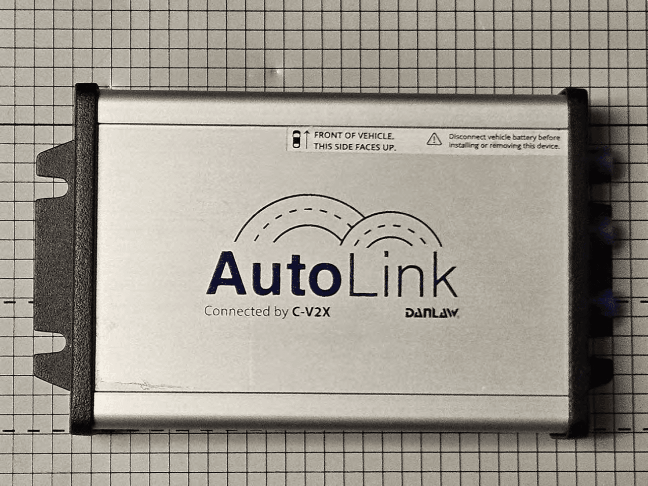
2AD9I9310039CV2XOBU
Mar 07, 2024C-V2X OBU
Equipment Class
ITO - Part 95L On Board Unit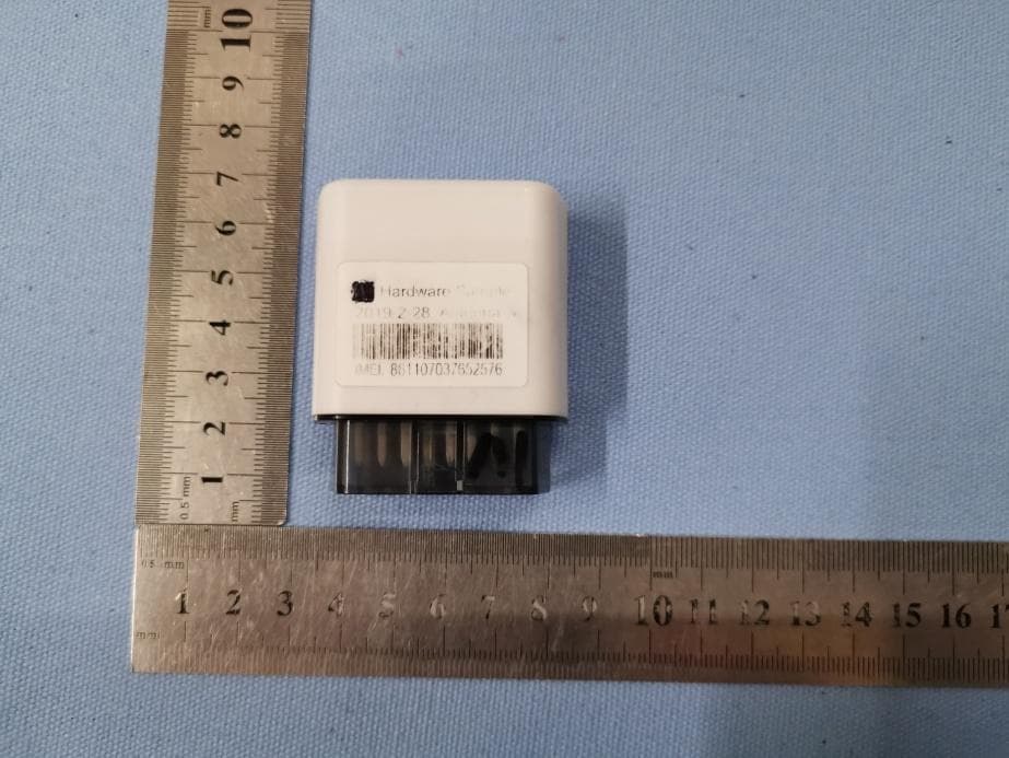
2AD9I-DL980QT
Jul 06, 2020OBDII Datalogger
Equipment Class
DXX - Part 15 Low Power Communication Device Transmitter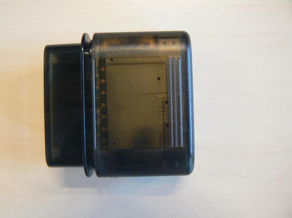
2AD9I-DL970
Jan 23, 2020Data Logger
Equipment Class
PCB - PCS Licensed Transmitter
2AD9I-BEACON
Aug 17, 2015BLE-Beacon
Equipment Class
DTS - Digital Transmission System