2AD9I-DL980QTOBDII Datalogger
DANLAW Inc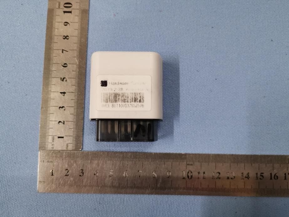
Click to zoom
Application Details
- Equipment Class
- DXX - Part 15 Low Power Communication Device Transmitter
- Date of Grant
- Jul 06, 2020
- Application Purpose
- Original Equipment
- Date of Application
- Jul 06, 2020
- Equipment Note
- OBDII Datalogger
- Frequency Range
- 2402.00000000 - 2480.00000000
- Company
- DANLAW Inc
- Country
- United States
Documents & Files
Document Text
Text extracted from the exhibit documents filed with the FCC. Open a document above to read the original.
Users Manual
DANLAW DATA LOGGER DL980QT USER MANUAL Revision: Initial Revision date: 4/24/2019 1.1 Product Overview Danlaw Data Logger – Vehicle Data Over the Air Danlaw’s Data Logger was developed to provide companies with an easy to install, wireless communication device for monitoring and logging vehicle network message data. The need for the DL980QT was driven by Danlaw’s own experience with Networked Automotive Electronics solution development, and perfected to provide our customers with the benefits of our experience. The Danlaw Data Logger provides: • Support for all major passenger car & light truck protocols • Simple plug-n-go via the vehicle’s OBDII connector • OBD Vehicle Data logging with real-time data stamp • LTE & 3G communication • Wi-Fi connectivity • Support for FTP, TCP/IP data transfer • Firmware Over-The-Air (FOTA) Re-flash • Rugged, compact field-hardened design • No external antenna connections needed • Completely self contained Danlaw Data Logger - Advantage DL980SW Features: • High Speed Data Upload – DL980 has been demonstrated to significantly redu ce the Data Upload time as compared to the speed of other wired and wireless OBDII interface solutions. • Stand Alone Simplicity – Easy plug in and even easier to use. No external connections needed. Eliminates the need for costly power adapters, antenna co nnections an d knowledgeable resources to install the module. • Portability – The DL980 has been designed to maximize in-the- field efficiency, light weight, robust, and compact design. • Low Cost Solution – Low data transmission cost due to optimized data transmission, cost effective hardware – no maintenance and no batteries. • Wifi Hot Spot Connectivity – lets you share Internet with your smartphone, tablet, media player, e-reader, other laptops • Flexible – Supports all major OEMs including: GM, Ford, DCX, Honda, Toyota, Nissan, BMW, Audi, Volvo and more. 1.2 Product Specifications Danlaw Data Logger - Specifications OPERATING VOLTAGE: 12V POWER CONSUMPTION: < 100 mA @ 12VDC (Data Upload) < 10 mA Average (during Sleep mode) TEMPERATURE RANGE: -30 °C to +65 °C (operating) HUMIDITY: 90% RH – non condensing CERTIFICATIONS: RoHS Compliant VEHICLE COMMUNICATION: Vehicle Protocol Support: GMLAN, FNOS, ISO-9141-2, SAE J1850 VPW, SAE J1850 PWM, ISO 14230-4, ISO 15765 (11bit CAN & 29bit CAN), SW CAN Vehicle Message Data: Time Stamped Event and Vehicle Message Bus Data Recording including: (All OEM Supported OBDII Data including: VIN, ODO, Time &Date, Vehicle Speed, module connect/disconnect events) PHYSICAL DIMENSIONS: Ultra Compact INSTALLATION TIME: 10 Seconds NUMBER OF TRIPS: Unlimited DATA RECORDING INTERVAL: Selectable (1 Hz and up) 2.0 Installation Instructions 1. Locate the OBD connector: If you are not able to locate the OBD connector, please refer to the Vehicle User Manual 2. Install the DL980QT device by plugging it into the OBD connector Warning: The device has to be installed in such a way that at all times a minimum distance of at least 20cm shall be kept between the device and the user. 3.0 Electronic Code of Federal Regulations The devices is subject to Part 15 of the Federal Rules / RSS-210 of Candian Rules and subject to certification procedure NOTICE: This device complies with Part 15 of the FCC Rules [and with Industry Canada licence-exempt RSS standard(s)]. Operation is subject to the following two conditions: (1) this device may not cause harmful interference, and (2) this device must accept any interference received, including interference that may cause undesired operation. Caution: changes or modifications not expressly approved by the manufacturer could void the user’s authority to operate the equipment Le présent appareil est conforme aux CNR d'Industrie Canada applicables aux appareils radio exempts de licence. L'exploitation est autorisée aux deux conditions suivantes: (1) l'appareil ne doit pas produire de brouillage, et (2) l'appareil doit accepter tout brouillage radioélectrique subi, même si le brouillage est susceptible d'en compromettre le fonctionnement. If you have any questions regarding safety or use case please contact Danlaw Inc. Office: 41131 Vincenti Court. Novi, MI 48375 USA. 3.0 Revision History 4/24/2019 Initial Release
Cover Letter(s)
< DANLAW Inc > O ffice of Engineering Technology Federal Communications Commission 7435 Oakland Mills Road Columbia, MD21046 Date: 06-16-2020 S ubject; Request for Long Term Confidentiality FCC ID: 2AD9I-DL980QT To Whom It May Concern, Pursuant to the provisions of the Commission’s rules Title 47 Sections §0.457 and §0.459, we are requesting the Commission to withhold the following attachment(s) as confidential documents from public disclosure indefinitely. Thes e documents contain detailed system and equipment descriptions and are considered as proprietary information in operation of the equipment. The public disclosure of these documents might be harmful to our company and would give competitors an unfair advantage in the market. Schematic Diagram Block Diagram Operational Description Part list Turn up procedure It i s our understanding that all measurement test reports, FCC ID label format and correspondence during the certification review process cannot be granted as confidential documents and this information will be available for public review once the grant of equipment authorization is issued. S incerely, S ignature: N ame: Eugenijus Sumskas Ti tle: GM Operations
Cover Letter(s)
DANLAW Inc Letter of Authorization Company: DANLAW Inc Address: 41131 Vincenti Court, Novi, Michigan 48375, United States Product Name: OBDII Datalogger Model Number(s): DL980QT Product Description: OBDII Datalogger We authorize MiCOM Labs Inc., 575 Boulder Court, Pleasanton, California 94566, USA, to act on our behalf on all matters concerning the certification of above named equipment. We declare that MiCOM Labs Inc. is allowed to forward all information related to the approval and certification of equipment to the regulatory agencies as required and to discuss any issues concerning the approval application. Any and all acts carried out by MiCOM Labs on our behalf shall have the same effect as acts of our own. Signature: Date: 06/16/2020 Name: Eugenijus Sumskas Title: GM Operations Company: Danlaw, Inc
External Photos
Test model number: DL980QT
ID Label/Location Info
Model No.: DL980QT Label location
ID Label/Location Info
尺寸:27.2x21.5mm,公差+0.1mm 4角R0.5mm 材质: 白色PET Model: DL980QT IMEI: 863867023076167 SN: 9041502030 Made in China IC: 24046-DL980QT FCC ID:2AD9I-DL980QT CO NTAINS FCC ID:XMR201605EC25A CO NTAINS IC:10224A-201611EC25A
Internal Photos
Tes st Model No.: DL980QQT
RF Exposure Info
FCC ID: 2AD9I-DL980QT RF Exposure Evaluation The criteria listed in the following table shall be used to evaluate the environment impact of human exposure to radio frequency (RF) radiation as specified in 1.1307(b) Limits for Maximum Permissible Exposure (MPE) Frequency range (MHz) Electric field strength (V/m) Magnetic field strength (A/m) Power density (mW/cm 2 ) Averaging time (minutes) (A) Limits for Occupational/Controlled Exposures 0.3–3.0 614 1.63 *(100) 6 3.0–30 1842/f 4.89/f *(900/f 2 ) 6 30–300 61.4 0.163 1.0 6 300–1500 f/300 6 1500–100,000 5 6 (B) Limits for General Population/Uncontrolled Exposure 0.3–1.34 614 1.63 *(100) 30 1.34–30 824/f 2.19/f *(180/f 2 ) 30 30–300 27.5 0.073 0.2 30 300–1500 f/1500 30 1500–100,000 1.0 30 f = frequency in MHz Friis transmission formula: Pd = (Pout*G)/(4*pi*r 2 ) Where Pd = power density in mW/cm 2 , Pout = output power to antenna in mW; G = gain of antenna in linear scale, Pi = 3.1416; R = distance between observation point and center of the radiator in cm Pd id the limit of MPE, 1 mW/cm 2 . If we know the maximum gain of the antenna and the total power input to the antenna, through the calculation, we will know the distance r where the MPE limit is reached. Test Procedure Software provided by client enabled the EUT to transmit and receive data at lowest, middle and highest channel individually. FCC ID: 2AD9I-DL980QT Test Result of RF Exposure Evaluation WCDMA Band II Channel Output power to antenna (mW) Power Density at R=20cm (mW/cm 2 ) Limit (mW/cm 2 ) Result Lowest (1852.4MHz) 230.144 0.05505 1.0 PASS Middle (1880.0MHz) 249.459 0.05967 1.0 PASS Highest (1907.6MHz) 233.346 0.05581 1.0 PASS Remark: antenna gain=0.8 dBi, Tune-up tolerance: 23±1 WCDMA Band IV Channel Output power to antenna (mW) Power Density at R=20cm (mW/cm 2 ) Limit (mW/cm 2 ) Result Lowest (1712.4MHz) 169.434 0.03960 1.0 PASS Middle (1732.4MHz) 187.932 0.04393 1.0 PASS Highest (1752.6MHz) 189.671 0.04433 1.0 PASS Remark: antenna gain=0.7 dBi, Tune-up tolerance: 22±1 WCDMA Band V Channel Output power to antenna (mW) Power Density at R=20cm (mW/cm 2 ) Limit (mW/cm 2 ) Result Lowest (826.4MHz) 246.037 0.04071 0.551 PASS Middle (836.6MHz) 239.332 0.03960 0.558 PASS Highest (846.6MHz) 241.546 0.03997 0.564 PASS Remark: antenna gain=-0.8 dBi, Tune-up tolerance: 23±1 LTE mode Band Frequency (MHz) Output power to antenna (dBm) Output power to antenna (mW) Power Density at R=20cm (mW/cm 2 ) Limit (mW/cm 2 ) Result LTE Band 2 1852.5 23.99 250.611 0.05994 1.0 PASS LTE Band 4 1732.5 23.96 248.886 0.05817 1.0 PASS LTE Band 12 714.5 24 251.189 0.04253 0.476 PASS Remark: antenna gain: Band 2: 0.8dBi, Band 4: 0.7dBi, Band 12: -0.7dBi. Tune-up tolerance: 23±1 FCC ID: 2AD9I-DL980QT WiFi 2.4Gmode Channel Output power to antenna (mW) Power Density at R=20cm (mW/cm 2 ) Limit (mW/cm 2 ) Result Lowest (2412MHz) 27.54 0.00613 1.0 PASS Middle (2437MHz) 26.42 0.00590 1.0 PASS Highest (2462MHz) 27.48 0.00613 1.0 PASS Remark: antenna gain=0.5dBi For BLE According to 447498 D01 General RF Exposure Guidance The 1-g and 10-g SAR test exclusion thresholds for 100 MHz to 6 GHz at test separation distances > 50 mm are determined by: {[Power allowed at numeric threshold for 50 mm in step a)] + [(test separation distance – 50 mm)·10]} mW, for > 1500 MHz and ≤ 6 GHz eirp = pt x gt = (EXd) 2 /30 where: pt = transmitter output power in watts, gt = numeric gain of the transmitting antenna (unitless), E = electric field strength in V/m, --- 10 ((dBuV/m)/20) /10 6 d = measurement distance in meters (m) ---3m So pt = (EXd) 2 /30 x gt Field strength =94.93 dBuV/m @3m Ant gain =0.5dBi, so Ant numeric gain= 1.122 So pt={ [10 94.93/20) /10 6 x 3] 2 /30x1.122}x1000 mW =0.832mW<96mW (illustrated in Appendix B)
Test Report
Global United Technology Services Co., Ltd. Report No.: GTS201904000001F02 Authorized Signature: Robinson Lo Laboratory Manager This results shown in this test report refer only to the sample(s) tested, this test report cannot be reproduced, except in full, without prior written permission of the company. The report would be invalid without specific stamp of test institute and the signatures of compiler and approver. Spectrum REPORT Applicant: DANLAW Inc Address of Applicant: 41131 Vincenti Court, Novi, Michigan 48375, United States Manufacturer: Asiatelco Technologies Co. Address of Manufacturer: #289 Bisheng Road,Building-8,3F,Zhangjiang Hi-tech Park,Pudong Shanghai 201204 China Equipment Under Test (EUT) Product Name: OBDII Datalogger Model No.: DL980QT FCC ID: 2AD9I-DL980QT Applicable standards: FCC CFR Title 47 Part 15 Subpart C Section 15.249 Date of sample receipt: March 01, 2019 Date of Test: March 01-14, 2019 Date of report issued: March 14, 2019 Test Result : PASS * * In the configuration tested, the EUT complied with the standards specified above. Report No.: GTS201904000001F02 Global United Technology Services Co., Ltd. No. 123-128, Tower A, Jinyuan Business Building, No.2, Laodong Industrial Zone, Xixiang Road, Baoan District, Shenzhen, Guangdong, China 518102 Telephone: +86 (0) 755 2779 8480 Fax: +86 (0) 755 2779 8960 Page 2 of 28 2 Version Version No. Date Description 00 March 14, 2019 Original Prepared By: Date: March 14, 2019 Project Engineer Check By: Date: March 14, 2019 Reviewer Report No.: GTS201904000001F02 Global United Technology Services Co., Ltd. No. 123-128, Tower A, Jinyuan Business Building, No.2, Laodong Industrial Zone, Xixiang Road, Baoan District, Shenzhen, Guangdong, China 518102 Telephone: +86 (0) 755 2779 8480 Fax: +86 (0) 755 2779 8960 Page 3 of 28 3 Contents Page 1 COVER PAGE ............................................................................................................................................ 1 2 VERSION .................................................................................................................................................. 2 3 CONTENTS .............................................................................................................................................. 3 4 TEST SUMMARY ..................................................................................................................................... 4 4.1 MEASUREMENT UNCERTAINTY ............................................................................................................ 4 5 GENERAL INFORMATION ...................................................................................................................... 5 5.1 GENERAL DESCRIPTION OF EUT ......................................................................................................... 5 5.2 TEST MODE ........................................................................................................................................ 7 5.3 DESCRIPTION OF SUPPORT UNITS ....................................................................................................... 7 5.4 TEST FACILITY .................................................................................................................................... 7 5.5 TEST LOCATION ................................................................................................................................. 7 5.6 ADDITIONAL INSTRUCTIONS ................................................................................................................. 7 6 TEST INSTRUMENTS LIST ..................................................................................................................... 8 7 TEST RESULTS AND MEASUREMENT DATA .................................................................................... 10 7.1 ANTENNA REQUIREMENT ................................................................................................................... 10 7.2 RADIATED EMISSION METHOD ........................................................................................................... 11 7.2.1 Field Strength of The Fundamental Signal ................................................................................ 13 7.2.2 Spurious emissions .................................................................................................................... 14 7.2.3 Bandedge emissions.................................................................................................................. 22 7.3 OCCUPY BANDWIDTH ........................................................................................................................ 26 8 TEST SETUP PHOTO ............................................................................................................................ 28 9 EUT CONSTRUCTIONAL DETAILS ..................................................................................................... 28 Report No.: GTS201904000001F02 Global United Technology Services Co., Ltd. No. 123-128, Tower A, Jinyuan Business Building, No.2, Laodong Industrial Zone, Xixiang Road, Baoan District, Shenzhen, Guangdong, China 518102 Telephone: +86 (0) 755 2779 8480 Fax: +86 (0) 755 2779 8960 Page 4 of 28 4 Test Summary Test Item Section Result Antenna requirement 15.203 Pass AC Power Line Conducted Emission 15.207 N/A Field strength of the fundamental signal 15.249 (a) Pass Spurious emissions 15.249 (a) (d)/15.209 Pass Band edge 15.249 (d)/15.205 Pass 20dB Occupied Bandwidth / 99% Occupied Bandwidth 15.215 (c) Pass Remarks: 1. Test according to ANSI C63.10: 2013. 2. Pass: The EUT complies with the essential requirements in the standard. 3. N/A: Not applicable. 4.1 Measurement Uncertainty Test Item Frequency Range Measurement Uncertainty Notes Radiated Emission 9kHz ~ 30MHz 4.54dB (1) Radiated Emission 30MHz ~ 1000MHz 5.34dB (1) Radiated Emission 1GHz ~ 26.5GHz 5.34dB (1) Note (1): The…
Text truncated - open the document above for the full version.
Test Setup Photos
Test model number: DL980QT Radiated Emission
Contact Information
Applicant
Eugenijus Sumskas(GM Operations)
Technical Contact
Test Firm
Global United Technology Services Co. Ltd.Robinson Lo
Technical Specifications
| # | Rule Parts | Frequency Range | Power Output |
|---|---|---|---|
| 1 | 15C | 2.40 GHz - 2.48 GHz | - |
Other Applications from DANLAW Inc
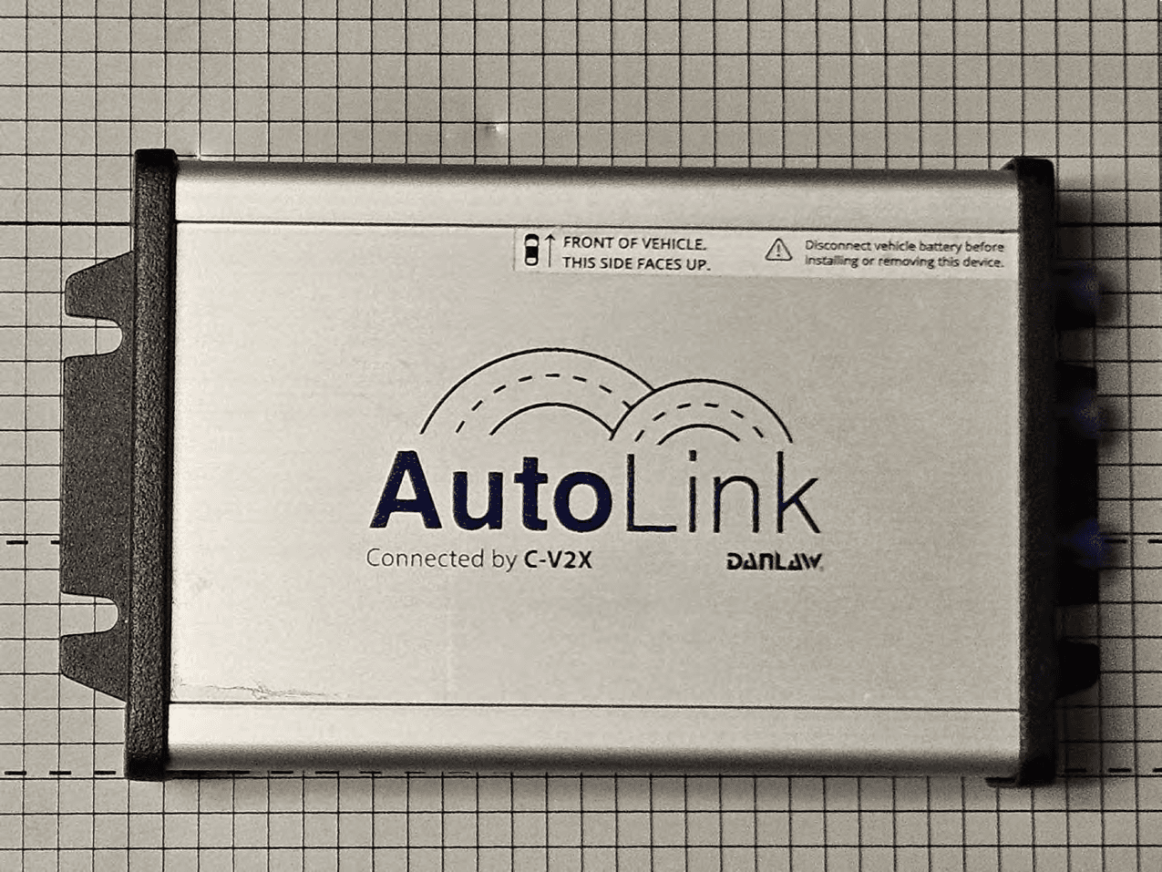
2AD9I9310039CV2XOBU
Mar 07, 2024C-V2X OBU
Equipment Class
ITO - Part 95L On Board Unit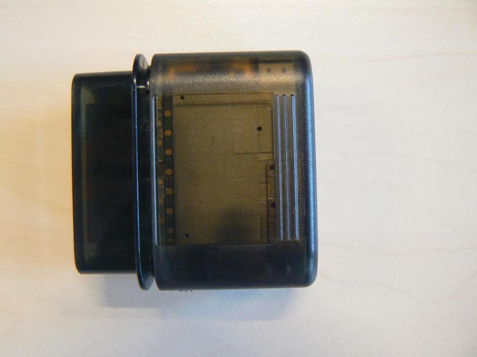
2AD9I-DL970
Jan 23, 2020Data Logger
Equipment Class
PCB - PCS Licensed Transmitter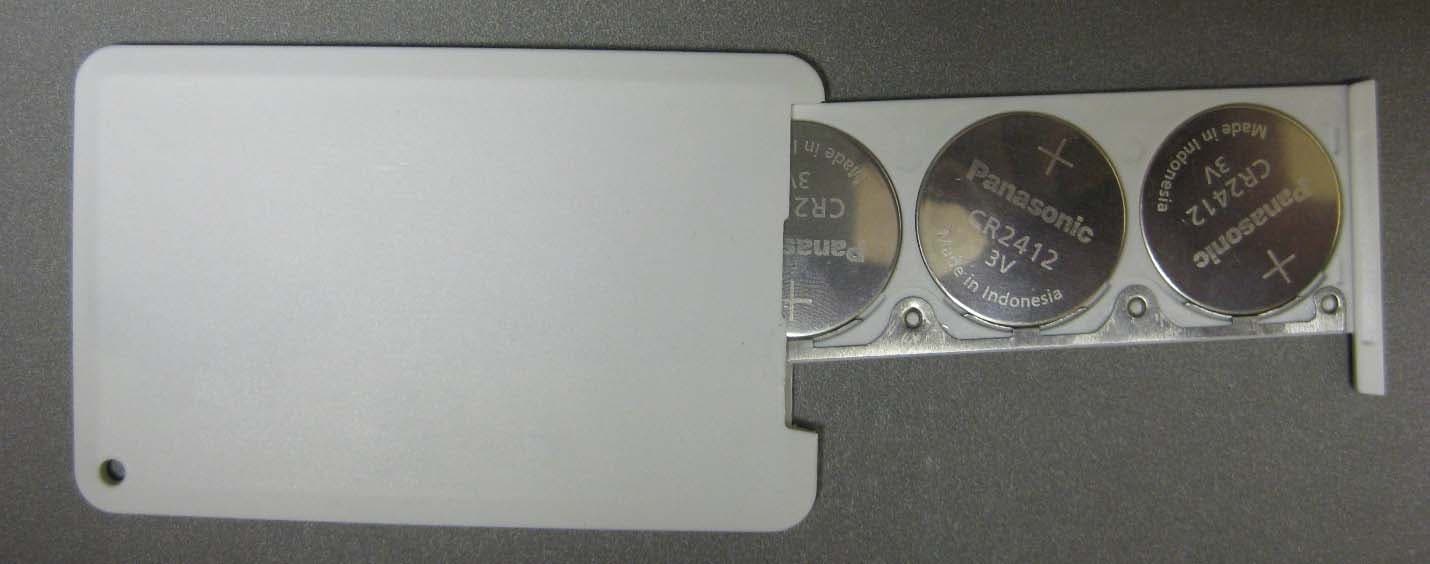
2AD9I-BEACON
Aug 17, 2015BLE-Beacon
Equipment Class
DTS - Digital Transmission System
2AD9I-DL815
Jun 10, 2015Data Logger Vehicular Transceiver
Equipment Class
DTS - Digital Transmission System