2ADCB-FCS7TSNBlue Tooth enabled Light Control
Acuity Brands Lighting, Inc.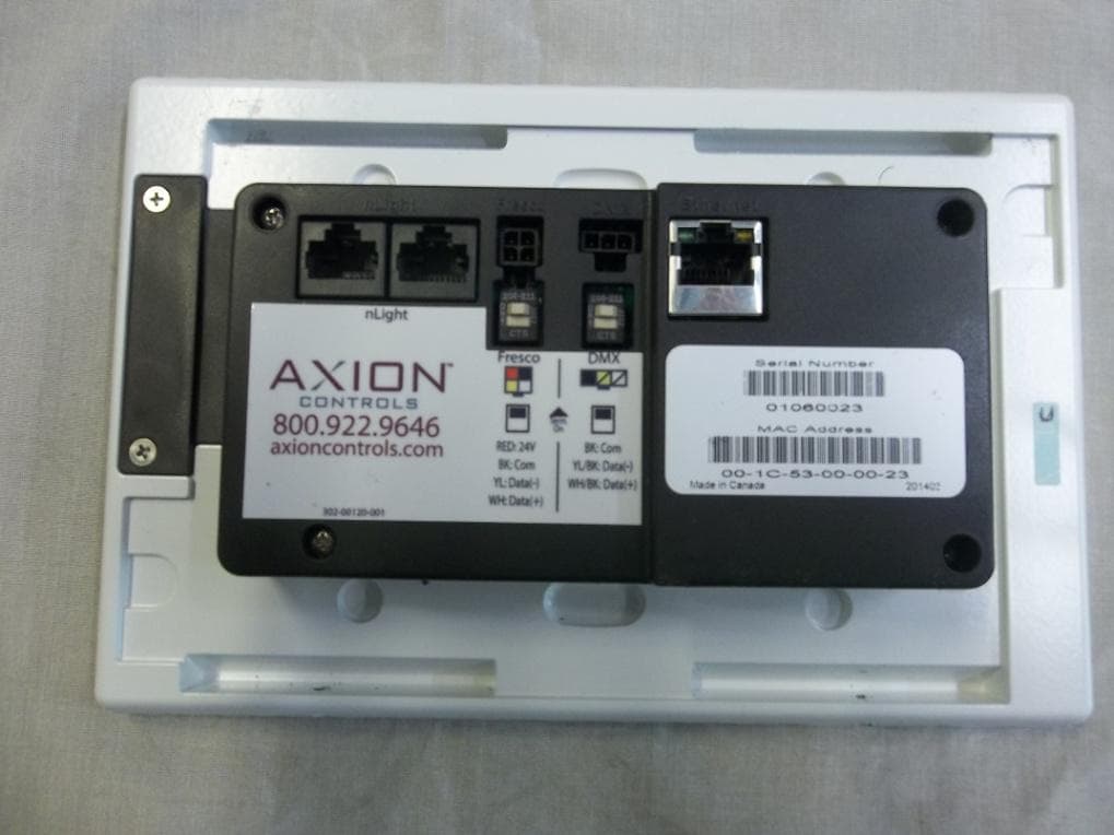
Click to zoom
Application Details
- Equipment Class
- DXX - Part 15 Low Power Communication Device Transmitter
- Date of Grant
- Dec 04, 2014
- Application Purpose
- Original Equipment
- Date of Application
- Dec 04, 2014
- Equipment Note
- Blue Tooth enabled Light Control
- Frequency Range
- 2402.00000000 - 2480.00000000
- Company
- Acuity Brands Lighting, Inc.
- Country
- United States
Documents & Files
Document Text
Text extracted from the exhibit documents filed with the FCC. Open a document above to read the original.
Users Manual
User Guide Based of FW 103.18 Lights On 2 Overview “Lights On” is what you will see when the room is off and when pressed will activate the first lighting scene. 1. This screen is displayed when the room lighting is OFF, and the screen IR proximity sensor has been activated 2. If the LIGHTS ON screen is not pressed, it will dim and then go dark after a set period of time. This timeout can be adjusted within the MENU>SCREEN setup 3. The FRESCO logo page will display when the screen goes into time out. 4. The LIGHTS OUT and/or the FRESCO logo screen settings can be set to “not display” if desired. This change is made within the MENU>SCREEN setup 3 Home Screen Overview Turn room lighting on/off, activate scenes, master raise/lower lighting level, access to lighting zones, menu access for system setup, and current date/time 1. Controller name is unique and modified within MENU settings 2. Scrollable scene bar displays up to 6 programmable scenes per page. Up to 36 scenes can be created per fresco station 3. Master control room on/off state, raise/lower current scene, and access additional lighting zones ADJUST 4. MENU accesses system setup 5. Date/Time displayed and setup within MENU 4 Lighting Channels Overview Control up to 36 individual zones of lighting using the sliders or rocker switch. Adjustments such as intensity, color and color temperature are also controllable here 1. Channels control individual areas of lighting. These can control zones or multiple zones (Groups) of lighting. Groups can be created within the system menu setup. The channel names can be personalized within the system setup settings 2. The icon (Attribute Control) below the channel intensity slider indicates additional control of DMX lighting such as color and color temperature 3. EDIT SCENES accesses scene setup and configuration. Once created scenes are displayed/accessed from the home screen 5 DMX RGB Control Overview Control color intensity, hue, and saturation for DMX controlled RGB fixtures 1. Raise or lower overall intensity for the lighting zone 2. RGB values are displayed as colors change. Input specific values be pressing any of the RGB value fields 3. Change overall color (hue) by pressing anyway in the color field 4. Change color saturation by touching anywhere in the large color box 6 DMX Tunable White Control Overview Control intensity, color temperature and hue for DMX controlled tunable white fixtures 1. Raise or lower overall intensity for the lighting zone 2. Adjust color temperature by sliding the handle (range is specific to fixture) 3. Adjust hue for added effect (only applicable to supported fixtures) 7 Scene Creation Overview Each fresco station supports up to 36 lighting scenes. Scenes can made up of multiple lighting channels, 1. Adjust individual channel intensity levels 2. If available adjust color and/or color temperature setting using by pressing the attribute icon 3. After making adjustments press EDIT SCENES 1. Assign new look to one of 36 new scenes or overwrite existing scene 8 Scene Creation (continued) Overview Each fresco station supports up to 36 lighting scenes. Scenes can made up of multiple lighting channels, 1. Create a new SCENE NAME 2. Set the transition time of the scene with FADE TIME 3. Select INCLUDED CHANNELS that allow specific lighting channels to be included/excluded within the scene 1. Choose which lighting channels will be included within the new scene 2. When finished press CLOSE 9 Home Screen Menu Overview Menu provides access to system settings. Setup user profiles and access control, system configuration, and hardware setup USERS establishes the profiles used for secured system access SCHEDULING is currently not implemented in this firmware version SETUP accesses system configuration settings DIAGNOSTIC displays system technical data LOG IN to access system controls as setup within USERS 10 Menu>Users Overview User profiles can be setup to establish secured access to system controls 1. LOG IN to access system control and setup 2. If any buttons within the MENU are “greyed out” it indicates limited system access 1. Default administrator username is ACUITY and password is 1234 2. Once logged in as administrator return to MENU>USERS to setup user profiles 11 Menu>Users (continued) Overview User profiles can be setup to establish secured access to system controls 1. 3 system access profiles are capable for setup A. Administrator- Full system access to control and configuration. Allows system profiles to be created B. Configure- Full system access to control and configuration C. Operate- Access to lighting controls only. No ability to create/modify scenes or access system configuration. Login is required to access fresco station 2. ADD additional profiles for system access 3. REMOVE a user from the system 4. EDIT an existing profile 12 Menu>Scheduling and Diagnostic Overview Scheduling stores system time clock control and scheduled lighting events. Diagnostic accesses system technical data that is used for troubleshooting system performance 1. Setting up SCHEDULING from the station is not currently supported. All schedules must be imported using the Fresco Studio PC tool 2. DIAGNOSITC is only needed for reference when needing to troubleshoot system performance 13 Menu>Setup Overview Setup accesses system configuration 1. SETUP allows access to system configuration for: A. System firmware B. Screen adjustments C. Network IP settings D. Lighting channels E. nLight devices F. DMX fixtures G. Lighting groups 14 Setup>About Overview System information including device serial number, operating firmware, network settings, and system reset 1. Fresco firmware version 2. Station serial number 3. Network/IP settings 4. nLight firmware version 5. SET TIME sets date and time for station 6. RESET is for system reboot which does not erase any stored system data 15 Setup>Screen Overview Modify screen settings and display behavior 1. The screen behavior can be set to react in 3 st…
Text truncated - open the document above for the full version.
Cover Letter(s)
CROSS REFERENCE FCC TO IC RSS-210/Gen FOR UST Project 14-0201 FCC ID: 2ADCB-FCS7TSN IC: 6715C-FCS7TSN TEST IC RSS-210 ISSUE 8 IC RSS-Gen ISSUE 3 FCC 15.249 Operation in the band 2400-2483.5 MHz Transmit Antenna Requirement RSS-210, A8.4(4) 15.203 Fundamental Peak Power RSS-210, A2.9 (a) 15.249 Antenna Conducted Spurious Emissions RSS-210, A2.9(b) 15.249 Restricted Bands RSS-210, 2.2 15.205 Bandwidths RSS-Gen 2.2 Transmitter Unwanted emissions RSS-Gen 4.9 15.209, 15.249 Receiver Spurious emissions RSS-Gen 4.10 15.109 Frequency Strengths and Frequency Bandwidths RSS-210, A1.1.2 15.231(c) Power Spectral Density RSS-210, A8.5 N/A Conducted ICES-003 15.207(a) & 15.107(a) Digital Device Radiated ICES-003 15.109(a) Modular Approval RSS-Gen 7.1.1 N/A Antenna Requirement RSS-Gen 7.1.4 15.203
Cover Letter(s)
Request for Confidentiality Date: ___October 24, 2014 _____ Subject: Confidentiality Request for: FCC ID: 2ADCB-FCS7TSN and IC: 6715C-FCS7TSN Pursuant to FCC 47 CRF 0.457(d) and 0.459 and IC RSP-100, Section 10, the applicant requests that a part of the subject FCC application be held confidential. Type of Confidentiality Requested Exhibit Short Term Permanent Block Diagrams Short Term Permanent Operation Description/Theory of Operation Short Term Permanent Schematics Acuity Brands Lighting has spent substantial effort in developing this product and it is one of the first of its kind in industry. Having the subject information easily available to "competition" would negate the advantage they have achieved by developing this product. Not protecting the details of the design will result in financial hardship. Permanent Confidentiality: The applicant requests the exhibits listed above as permanently confidential be permanently withheld from public review due to materials that contain trade secrets and proprietary information not customarily released to the public. NOTE for Industry Canada Applications: The applicant understands that until such time that IC distinguishes between Short Term and Permanent Confidentiality, either type of marked exhibit above will simply be marked Confidential when submitted to IC. Sincerely, By: __________________________ ___Sandi McEnery__- Agent (Signature/Title) (Print name)
Cover Letter(s)
3505 Francis Circle, Alpharetta, GA 30004 PH: 770-740-0717 Fax: 770-740-1508 www.ustech-lab.com December 10, 2014 Timco Engineering Inc. 849 NW State Road 45 Newberry, FL 32669 SUBJECT: Error in Report for ACUITY BRANDS LIGHTING, INC - FCC ID: 2ADCBFCS7TSN - JOB #: 1978UC14 and IC: 6715C-FCS7TSN - JOB #: 1978IC14 Dear Timco, It has come to our attention that the test report for the FCC and IC Certification for the product referenced above cites the incorrect type of antenna used by the radio module. The originally submitted test report cited a trace antenna when, in fact, the radio uses a chip antenna. We have uploaded a corrected report and respectfully ask that you notify the FCC and Industry Canada of the correction made to Page 17, Table 4, and have the previously submitted test report superseded by this corrected version. Sincerely, Sandi McEnery Agent
External Photos
US Tech Test Report: FCC Part 15.249/ RSS 210 Report Number: 14-0201 Customer: Acuity Brands Lighting FCC ID: 2ADCB-FCS7TSN IC: 6715C-FCS7TSN Issue Date: September 3, 2014 Model: FCS 7TSN EXTERNAL PHOTOGRAPHS Photo 1 – Top of EUT US Tech Test Report: FCC Part 15.249/ RSS 210 Report Number: 14-0201 Customer: Acuity Brands Lighting FCC ID: 2ADCB-FCS7TSN IC: 6715C-FCS7TSN Issue Date: September 3, 2014 Model: FCS 7TSN Photo 2 – Back of EUT US Tech Test Report: FCC Part 15.249/ RSS 210 Report Number: 14-0201 Customer: Acuity Brands Lighting FCC ID: 2ADCB-FCS7TSN IC: 6715C-FCS7TSN Issue Date: September 3, 2014 Model: FCS 7TSN Photo 3 – Bottom of EUT US Tech Test Report: FCC Part 15.249/ RSS 210 Report Number: 14-0201 Customer: Acuity Brands Lighting FCC ID: 2ADCB-FCS7TSN IC: 6715C-FCS7TSN Issue Date: September 3, 2014 Model: FCS 7TSN Photo 4 – Left Side of EUT US Tech Test Report: FCC Part 15.249/ RSS 210 Report Number: 14-0201 Customer: Acuity Brands Lighting FCC ID: 2ADCB-FCS7TSN IC: 6715C-FCS7TSN Issue Date: September 3, 2014 Model: FCS 7TSN Photo 5 – Top of EUT US Tech Test Report: FCC Part 15.249/ RSS 210 Report Number: 14-0201 Customer: Acuity Brands Lighting FCC ID: 2ADCB-FCS7TSN IC: 6715C-FCS7TSN Issue Date: September 3, 2014 Model: FCS 7TSN Photo 2 – Right Side of EUT
ID Label/Location Info
nLight TM 302-00120-001 FrescoDMX RED: 24V BK: Com YL: Data( -) WH: Data( +) BK: Com YL/BK: Data( -) WH/BK: Data( +) Term. On Acuity Brands Lighting, Inc Model #: FCS 7TSN IC: 6715C-FCS7TSN FCC ID: 2ADCB-FCS7TSN THIS DEVICE COMPLIES WITH PART 15 OF THE FCC RULES. OPERATION IS SUBJECT TO THE FOLLOWING TWO CONDITIONS. (1) THIS DEVICE MAY NOT CAUSE HARMFUL INTERFERENCE, AND (2) THIS DEVICE MUST ACCEPT ANY INTERFERENCE RECEIVED, INCLUDING INTERFERENCE THAT MAY CAUSE UNDESIRED OPERATION 800.535.2465 www.acuitycontrols.com Fresco ™ US Tech Test Report: FCC Part 15.249/ RSS 210 Report Number: 14-0201 Customer: Acuity Brands Lighting FCC ID: 2ADCB-FCS7TSN IC: 6715C-FCS7TSN Issue Date: September 3, 2014 Model: FCS 7TSN Label Location Label will be placed on Back of Equipment as Indicated in Photograph LABEL GOES HERE
Internal Photos
US Tech Test Report: FCC Part 15.249/RSS 210 Report Number: 14-0201 Customer: Acuity Brands Lighting FCC ID: 2ADCB-FCS7TSN IC: 6715C-FCS7TSN Issue Date: September 3, 2014 Model: FCS 7TSN INTERNAL PHOTOGRAPHS Photo 1- Back of EUT with Back Cover Removed US Tech Test Report: FCC Part 15.249/RSS 210 Report Number: 14-0201 Customer: Acuity Brands Lighting FCC ID: 2ADCB-FCS7TSN IC: 6715C-FCS7TSN Issue Date: September 3, 2014 Model: FCS 7TSN Photo 2- Right Side of EUT with Back Cover Removed US Tech Test Report: FCC Part 15.249/RSS 210 Report Number: 14-0201 Customer: Acuity Brands Lighting FCC ID: 2ADCB-FCS7TSN IC: 6715C-FCS7TSN Issue Date: September 3, 2014 Model: FCS 7TSN Photo 3- Top of EUT with Back Cover Removed US Tech Test Report: FCC Part 15.249/RSS 210 Report Number: 14-0201 Customer: Acuity Brands Lighting FCC ID: 2ADCB-FCS7TSN IC: 6715C-FCS7TSN Issue Date: September 3, 2014 Model: FCS 7TSN Photo 4- Left Side of EUT with Back Cover Removed US Tech Test Report: FCC Part 15.249/RSS 210 Report Number: 14-0201 Customer: Acuity Brands Lighting FCC ID: 2ADCB-FCS7TSN IC: 6715C-FCS7TSN Issue Date: September 3, 2014 Model: FCS 7TSN Photo 5- Bottom of EUT with Back Cover Removed US Tech Test Report: FCC Part 15.249/RSS 210 Report Number: 14-0201 Customer: Acuity Brands Lighting FCC ID: 2ADCB-FCS7TSN IC: 6715C-FCS7TSN Issue Date: September 3, 2014 Model: FCS 7TSN Photo 6- Front Side of Circuit Board #1 US Tech Test Report: FCC Part 15.249/RSS 210 Report Number: 14-0201 Customer: Acuity Brands Lighting FCC ID: 2ADCB-FCS7TSN IC: 6715C-FCS7TSN Issue Date: September 3, 2014 Model: FCS 7TSN Photo 9- Back Side of Circuit Board #1 with Circuit Board #2 Attached US Tech Test Report: FCC Part 15.249/RSS 210 Report Number: 14-0201 Customer: Acuity Brands Lighting FCC ID: 2ADCB-FCS7TSN IC: 6715C-FCS7TSN Issue Date: September 3, 2014 Model: FCS 7TSN Photo 8- Back Side of Circuit Board #1 with Circuit Board #2 Removed US Tech Test Report: FCC Part 15.249/RSS 210 Report Number: 14-0201 Customer: Acuity Brands Lighting FCC ID: 2ADCB-FCS7TSN IC: 6715C-FCS7TSN Issue Date: September 3, 2014 Model: FCS 7TSN Photo 9- Front Side of Circuit Board #2 US Tech Test Report: FCC Part 15.249/RSS 210 Report Number: 14-0201 Customer: Acuity Brands Lighting FCC ID: 2ADCB-FCS7TSN IC: 6715C-FCS7TSN Issue Date: September 3, 2014 Model: FCS 7TSN Photo 10- Back Side of Circuit Board #2 US Tech Test Report: FCC Part 15.249/RSS 210 Report Number: 14-0201 Customer: Acuity Brands Lighting FCC ID: 2ADCB-FCS7TSN IC: 6715C-FCS7TSN Issue Date: September 3, 2014 Model: FCS 7TSN Photo 11- Back Side of EUT with Circuit Board #1 Removed US Tech Test Report: FCC Part 15.249/RSS 210 Report Number: 14-0201 Customer: Acuity Brands Lighting FCC ID: 2ADCB-FCS7TSN IC: 6715C-FCS7TSN Issue Date: September 3, 2014 Model: FCS 7TSN Photo 12- Bottom of EUT with Circuit Board #1 Removed US Tech Test Report: FCC Part 15.249/RSS 210 Report Number: 14-0201 Customer: Acuity Brands Lighting FCC ID: 2ADCB-FCS7TSN IC: 6715C-FCS7TSN Issue Date: September 3, 2014 Model: FCS 7TSN Photo 13- Left Side of EUT with Circuit Board #1 Rmoved US Tech Test Report: FCC Part 15.249/RSS 210 Report Number: 14-0201 Customer: Acuity Brands Lighting FCC ID: 2ADCB-FCS7TSN IC: 6715C-FCS7TSN Issue Date: September 3, 2014 Model: FCS 7TSN Photo 14- Top of EUT with Circuit Board #1 Removed US Tech Test Report: FCC Part 15.249/RSS 210 Report Number: 14-0201 Customer: Acuity Brands Lighting FCC ID: 2ADCB-FCS7TSN IC: 6715C-FCS7TSN Issue Date: September 3, 2014 Model: FCS 7TSN Photo 15- Right Side of EUT with Circuit Board #1 Removed US Tech Test Report: FCC Part 15.249/RSS 210 Report Number: 14-0201 Customer: Acuity Brands Lighting FCC ID: 2ADCB-FCS7TSN IC: 6715C-FCS7TSN Issue Date: September 3, 2014 Model: FCS 7TSN Photo 16- Top of Circuit Board #3, with Radio US Tech Test Report: FCC Part 15.249/RSS 210 Report Number: 14-0201 Customer: Acuity Brands Lighting FCC ID: 2ADCB-FCS7TSN IC: 6715C-FCS7TSN Issue Date: September 3, 2014 Model: FCS 7TSN Photo 17- Back of Circuit Board #3 US Tech Test Report: FCC Part 15.249/RSS 210 Report Number: 14-0201 Customer: Acuity Brands Lighting FCC ID: 2ADCB-FCS7TSN IC: 6715C-FCS7TSN Issue Date: September 3, 2014 Model: FCS 7TSN Photo 17- Radio on Circuit Board #3 US Tech Test Report: FCC Part 15.249/RSS 210 Report Number: 14-0201 Customer: Acuity Brands Lighting FCC ID: 2ADCB-FCS7TSN IC: 6715C-FCS7TSN Issue Date: September 3, 2014 Model: FCS 7TSN Photo 18- Back of EUT with all PCBs Removed
RF Exposure Info
US Tech Test Report: FCC Part 15.249/ RSS 210 Report Number: 14-0201 Customer: Acuity Brands Lighting FCC ID: 2ADCB-FCS7TSN IC: 6715C-FCS7TSN Issue Date: September 3, 2014 Model: FCS 7TSN Maximum Public Exposure to RF (MPE) The maximum exposure level to the public from the RF power of the EUT shall not exceed a power density, S, of 1 mW/cm 2 at a distance, d, of 20 cm from the EUT. Therefore, for: Declared maximum output power: +4 dBm Highest Gain Antenna PCB Trace Antenna = 3.0 dBi Peak Power (Watts) = 0.0025 (Manufacture’s claimed highest output power) Gain of Transmit Antenna = 3.0 dB i = 1.99, numeric (from Table 3 of Test Report) d = Distance = 20.0 cm = 0.20 m S = (PG/ 4d 2 ) = EIRP/4A = 0.0025(1.99)/4*π*0.20*0.20 = 0.0050/0.5027 = 0.0099 W/m 2 = (W/m 2 ) (1m 2 /W) (0.1 mW/cm 2 ) = 0.00099 mW/cm 2 which is < less than 1.0 mW/cm 2
Test Report
Page 1 of 36 Application for US Code Title 47, Part 2, Subpart J, Section 2.947, Certification Per Part 15, Subpart C, for Intentional Radiators, Section 15.249, Intentional Radiator Operating within the Band 2400 MHz to 2483.5 MHz And US Code Title 47, Part 2, Subpart J, Section 2.902, Verification Per Part 15, Subpart B, for Unintentional Radiators, section 15.101, 15.107 and 15.109 For the Acuity Brands Lighting Model: FCS 7TSN UST Project: 14-0201 Test Date(s): July 30, 2014 and September 2-10, 2014 Issue Date: September 23, 2014 3505 Francis Circle Alpharetta, GA 30004 PH: 770-740-0717 Fax: 770-740-1508 www.ustech-lab.com Page 2 of 36 I certify that I am authorized to sign for the test facility and that all of the statements in this report and in the Exhibits attached hereto are true and correct to the best of my knowledge and belief: US TECH (Agent Responsible For Test): By: Name: Alan Ghasiani Title: Consulting Engineer - President Date: September 23, 2014 This report shall not be reproduced except in full. This report may be copied in part only with the prior written approval of US Tech. The results contained in this report are subject to the adequacy and representative character of the sample provided. 3505 Francis Circle Alpharetta, GA 30004 PH: 770-740-0717 Fax: 770-740-1508 www.ustech-lab.com US Tech Test Report: FCC Part 15.249/RSS 210 Report Number: 14-0201 Customer: Acuity Brands Lighting FCC ID: 2ADCB-FCS7TSN IC: 6715C-FCS7TSN Issue Date: September 23, 2014 Model: FCS 7TSN Page 3 of 36 MEASUREMENT/TECHNICAL REPORT COMPANY NAME: Acuity Brands Lighting MODEL(S): FCS 7TSN FCC ID: 2ADCB-FCS7TSN IC: 6715C-FCS7TSN DATE: September 23, 2014 This report concerns (check one): Original grant X Class II change_____ Equipment type: Intentional Radiator Operating within the bands 2400-2483.5 MHz Deferred grant requested per 47 CFR 0.457(d) (1) (ii)? yes_____ No X If yes, defer until:_________________ date N.A. agrees to notify the Commission by N.A. date of the intended date of announcement of the product so that the grant can be issued on that date. Report prepared by: US Tech 3505 Francis Circle Alpharetta, GA 30004 Phone Number: (770) 740-0717 Fax Number: (770) 740-1508 US Tech Test Report: FCC Part 15.249/RSS 210 Report Number: 14-0201 Customer: Acuity Brands Lighting FCC ID: 2ADCB-FCS7TSN IC: 6715C-FCS7TSN Issue Date: September 23, 2014 Model: FCS 7TSN Page 4 of 36 SUMMARY OF TEST REQUIREMENTS FCC Requirement Title Disposition 15.205 Restricted Bands Pass 15.207 Intentional Radiator Power Line Conducted Pass Emissions 15.209 Intentional Radiator Radiated Emissions Pass 15.249(a) Fundamental Field Strength Pass 15.107 Unintentional Radiator Power Line Conducted Pass Emissions 15.109 Unintentional Radiator Radiated Emissions Pass N/A = Not applicable for this unit. US Tech Test Report: FCC Part 15.249/RSS 210 Report Number: 14-0201 Customer: Acuity Brands Lighting FCC ID: 2ADCB-FCS7TSN IC: 6715C-FCS7TSN Issue Date: September 23, 2014 Model: FCS 7TSN Page 5 of 36 Table of Contents 1 General Information ........................................................................................ 8 1.1 Purpose of this Report .............................................................................. 8 1.2 Product Description ................................................................................... 8 1.3 Related Submittal(s)/Grant(s) ................................................................... 8 1.3.1 The EUT is subject to the following FCC authorizations: .................... 8 1.3.2 Certification of the Transmitter ............................................................ 9 2 Tests and Measurements ............................................................................... 9 2.1 Configuration of Tested System ................................................................. 9 2.2 EUT Characterization ............................................................................... 11 2.3 Test Facility ............................................................................................. 11 2.4 Test Equipment ....................................................................................... 12 2.5 Modifications to EUT ............................................................................... 13 2.6 Measurement Standards (CFR 15.31) .................................................... 13 2.7 Frequency Range of Radiated Measurements (CFR 15.33) ................... 14 2.7.1 Frequency Range for Intentional Radiators ......................................... 14 2.7.2 Frequency Range for Unintentional Radiators .................................... 14 2.7.3 Measurement Detector Function and Bandwidth (CFR 15.35) .......... 14 2.8 Antenna Requirement (CFR 15.203) ...................................................... 17 2.9 Intentional Radiator, Power Line Conducted Emissions (CFR 15.207) ... 17 2.10 Restricted Bands of Operation (CFR 15.205) ......................................... 17 2.11 Intentional Radiator, Radiated Emissions (CFR 15.209, 15.249 (a), (e)) 18 2.12 20 dB Bandwidth Measurement per CFR 15.249, 99% Occupied Bandwidth (IC RSS 210, A8.1)......................................................................... 22 2.13 Band Edge Measurements (CFR15.249(d))............................................. 26 2.13.1 High Band Edge ................................................................................. 27 2.13.2 Low Band Edge .................................................................................. 28 2.13.3 Restricted Band Evaluation ................................................................ 29 2.14 Unintentional Radiator, Power Conducted Emissions (CFR 15.107) ....... 31 2.15 Unintentional Radiator, Radiated Emissions (CFR 15.109) ..................... 33 2.16 Measurement Uncertainty ........................................................................ 36 2.16.1 Conducted Emissions Measurement Uncertainty ...............…
Text truncated - open the document above for the full version.
Test Setup Photos
US Tech Test Report: FCC Part 15.249/ RSS 210 Report Number: 14-0201 Customer: Acuity Brands Lighting FCC ID: 2ADCB-FCS7TSN IC: 6715C-FCS7TSN Issue Date: September 3, 2014 Model: FCS 7TSN TEST CONFIGURATION PHOTOGRAPHS Photo 1- Radiated Emissions Test Setup, Front Photo 2- Radiated Emissions Test Setup, 30 MHz to 200 MHz, Back US Tech Test Report: FCC Part 15.249/ RSS 210 Report Number: 14-0201 Customer: Acuity Brands Lighting FCC ID: 2ADCB-FCS7TSN IC: 6715C-FCS7TSN Issue Date: September 3, 2014 Model: FCS 7TSN Photo 3- Radiated Emissions Test Setup, 200 MHz to 1000 MHz, Back Photo 4- Radiated Emissions Test Setup, 1GHz and Above, Back US Tech Test Report: FCC Part 15.249/ RSS 210 Report Number: 14-0201 Customer: Acuity Brands Lighting FCC ID: 2ADCB-FCS7TSN IC: 6715C-FCS7TSN Issue Date: September 3, 2014 Model: FCS 7TSN Photo 5- Radiated Emissions Test Setup, below 30 MHz, Back US Tech Test Report: FCC Part 15.249/ RSS 210 Report Number: 14-0201 Customer: Acuity Brands Lighting FCC ID: 2ADCB-FCS7TSN IC: 6715C-FCS7TSN Issue Date: September 3, 2014 Model: FCS 7TSN Photo 6- Conducted Emissions Test Setup
Contact Information
Applicant
Vaske Mikani
Test Firm
US TechGeorge Yang
Technical Specifications
| # | Rule Parts | Frequency Range | Power Output |
|---|---|---|---|
| 1 | 15C | 2.40 GHz - 2.48 GHz | - |
Other Applications from Acuity Brands Lighting, Inc.
2ADCB-PLSSSA
Aug 07, 2026Push-to-Lock Sensor SensorSwitch Air
Equipment Class
DTS - Digital Transmission System
2ADCB-TLSSSA
Apr 15, 2026Wireless Twist-to-Lock Sensor SensorSwitch AIR
Equipment Class
DTS - Digital Transmission System
2ADCB-DELC
Jan 25, 2023BLE Module for Lighting Applications
Equipment Class
DTS - Digital Transmission System2ADCB-RES7CD
Dec 28, 2020nLightAir RES7CD RF Module
Equipment Class
DTS - Digital Transmission System
2ADCB-ATG2
May 17, 2020Asset Tag
Equipment Class
DTS - Digital Transmission System