2ADXK-1663Baby Monitor
Shenzhen Viatom Technology Co., Ltd.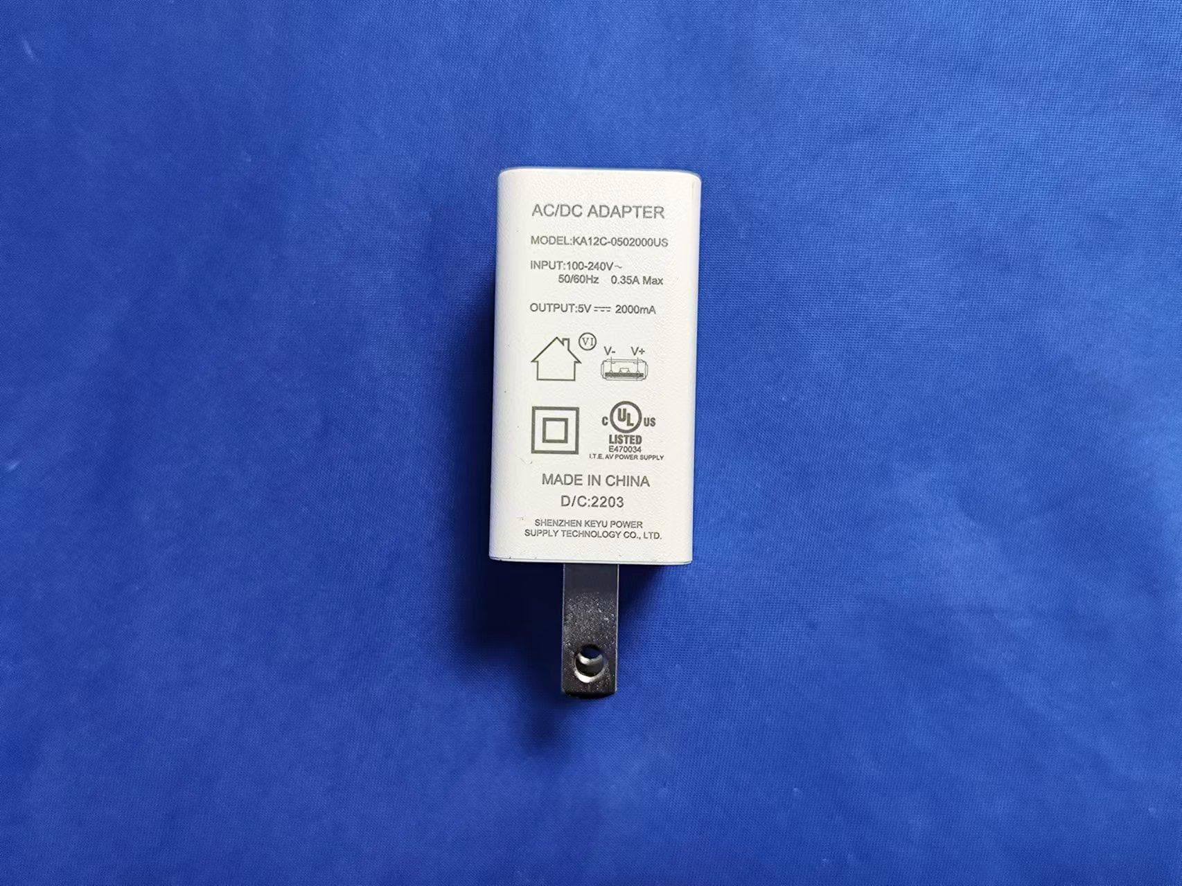
Click to zoom
Application Details
- Equipment Class
- DTS - Digital Transmission System
- Date of Grant
- Nov 22, 2022
- Application Purpose
- Original Equipment
- Date of Application
- Nov 22, 2022
- Equipment Note
- Baby Monitor
- Frequency Range
- 2412.00000000 - 2462.00000000
- Country
- China
Documents & Files
Document Text
Text extracted from the exhibit documents filed with the FCC. Open a document above to read the original.
Users Manual
Baby Monitor User Manual Contact us: [email protected] Website: www.getbabytone.com Contents 1. Introduction .............................................. 1 2. Warnings ................................................... 1 3. Packing List .............................................. 2 4. Guide to Parts .......................................... 3 4.1. Overview of the Camera Unit..... 3 4.2. Overview of the Baby Monitor ... 4 5. Activate the Device ................................ 6 5.1. Camera Unit .................................. 6 5.2. Baby Monitor ................................. 6 5.3. Pairing ............................................ 6 6. Using the Device ..................................... 7 6.1. Setting up ...................................... 7 6.2. Pan, tilt, and zoom ....................... 8 6.3. Screenshot (TF card required) ... 8 6.4. Night vision mode ......................... 9 6.5. Talk Mode ....................................... 9 6.6. Video on/off ................................... 9 6.7. Volume ............................................ 9 7. Baby Monitor Menu Options ................. 9 7.1. Playback (TF card required) ..... 10 7.2. Vox Monitoring ............................ 10 7.3. Music ............................................ 10 7.4. Feeding Clock ............................... 11 7.5. Camera .......................................... 11 7.6. Bluetooth ..................................... 12 7.7. General settings ......................... 14 8. Maintenance ......................................... 15 9. Troubleshooting .................................... 16 10.Specifications ....................................... 18 11. Symbols ................................................. 19 12.FCC Statement .................................... 20 1 1. Introduction It is intended to monitor infants or children when they are alone through real-time images captured by the camera and audio communication. Also, paired with the optional device Baby Sleep Monitor, data of oxygen level and heart rate can be tracked and displayed through the integrated communication module of the camera, ensuring your acknowledgement of the child’s conditions. 2. Warnings This device is compliant with all relevant standards regarding electromagnetic fields and is, when handled as described in the User's Guide, safe to use. Therefore, always read the instructions in this User's Guide carefully before using the device. ⚫ Adult assembly is required. Keep small parts away from children when assembling. ⚫ This product is not a toy. Do not allow children to play with it. ⚫ This product is not a substitute for responsible adult supervision. ⚫ Keep this user's guide for future reference. ⚫ Keep the cords out of the reach of children. 2 ⚫Do not cover the product with a towel or blanket. ⚫Test this monitor and all its functions so that you are familiar with it prior to actual use. ⚫Do not use the product in damp areas or close to water. ⚫Do not install the product in extreme cold or heat, direct sunlight, or close to a heat source. ⚫Only use the chargers and power adapters provided. Do not use other chargers or power adapters as this may damage the device and battery pack. ⚫Do not touch the plug contacts with sharp or metal objects. ⚫Connect the power adapters to easily accessible electrical outlets. 3.Packing List ⚫Baby Monitor (Display screen, Model:BM-1R) ⚫Camera Unit ( Model:BM-1T) ⚫Charging Plug and Power Cable for Baby Monitor ⚫Charging Plug and Power Cable for Camera Unit ⚫Bracket ⚫User Manual 3 4.Guide to Parts 4.1. Overview of the Camera Unit 1.Camera Lens 2.Indicator LED 3.Temperature & Humidity Sensor 4.Speaker 5.Reset Key 6.Power Adapter Socket 7.Bracket 8.Screw Holes 9.Connection Hole Note: You can either fix the camera to anywhere you need by adjusting the bracket or to the wall after inserting screws. 1 2 3 4 5 6 7 9 8 4 4.2. Overview of the Baby Monitor 1.LCD Screen 2.Joystick Camera mode: Tilt up or down, pan left or right. Menu mode: Up, down, left, right. 3.OK Key 4.Menu/Exit Key Press to open the Menu options or exit. 5.Indicator LED Blue light: talking. Green light: charging, it turns off when charging is complete. 6.Talk Key Press to speak to your baby. 7.Microphone 8.TF Card Slot 9.Power Adapter Socket 10.Power Key Long press to power on/off. Short press to turn off/wake up screen. 11.Volume Key 12.Speaker 13.Antenna Lift the antenna for optimal signal reception. 6 2 3 4 8 5 9 1 13 12 10 11 7 5 Baby Monitor menu icons Icon Description Talk mode ON Recording Volume Ambient humidity Ambient temperature TF card full Vox monitor state Signal intensity Oxygen level (if paired with ‘Baby Sleep Monitor’) Heart rate(if paired with ‘Baby Sleep Monitor’) * The Baby Sleep Monitor is an optional device. * When the TF card is full, it will loop recording, please export the needed data (MENU>Camera>Record>Export) from the TF card before it is overwritten. 6 5.Activate the Device 5.1. Camera Unit a)Connect the micro USB interface of the power adapter to the Camera Unit, and the other end to the electrical outlet. Note: ⚫Compatible power adapter output: DC 5V, 1A. 5.2. Baby Monitor a)Connect the Type C interface of the power adapter to the Baby Monitor and the other end to the electrical outlet for charging. b)Once the charging is finished. Press and hold the Power key for 3 seconds to turn on the Baby Monitor. c)When the Camera Unit and Baby Monitor are all switched on, the pairing process will begin automatically. Note: ⚫Compatible power adapter output: DC 5V, 2A. 5.3. Pairing The Camera Unit has been paired with your Baby Monitor before delivery. a)Switch on the two units, the Baby Monitor will show a “No Camera” symbol . 7 b)Wait patiently for automatic pairing, you can monitor the pairing process through the LED light on the camera. Indicator Status Description Purple, red, and blue light 30s alternating flashing Power on, waiting for configuration Red light 30s quick f…
Text truncated - open the document above for the full version.
Cover Letter(s)
ShenzhenViatomTechnologyCo.,Ltd. AgentAuthorization Company:ShenzhenViatomTechnologyCo.,Ltd. Address:4E,3#,TingweiIndustrialPark,HonglangNorth2ndRoad,BaoanDistrict, Shenzhen,518057,China ProductName:BabyMonitor ModelNumber(s):BM-1R ProductDescription:BabyMonitor WeauthorizeMiCOMLabsInc.,575BoulderCourt,Pleasanton,California94566,USA, toactonourbehalfonallmattersconcerningthecertificationofabovenamed equipment. WedeclarethatMiCOMLabsInc.isallowedtoforwardallinformationrelatedtothe approvalandcertificationofequipmenttotheregulatoryagenciesasrequiredandto discussanyissuesconcerningtheapprovalapplication.Anyandallactscarriedoutby MiCOMLabsonourbehalfshallhavethesameeffectasactsofourown. Signature:Date:2022.11.06 Name:BingWang Title:Manager Company:ShenzhenViatomTechnologyCo.,Ltd.
Cover Letter(s)
ShenzhenViatomTechnologyCo.,Ltd. OfficeofEngineeringTechnology FederalCommunicationsCommission 7435OaklandMillsRoad Columbia,MD21046 USA Date:2022.11.06 Subject;RequestforConfidentiality FCCID:2ADXK-1663 ToWhomItMayConcern, PursuanttotheprovisionsoftheCommission’srulesTitle47Sections§0.457and§0.459,we arerequestingtheCommissiontowithholdthefollowingattachment(s)asconfidential documentsfrompublicdisclosureindefinitely. Thesedocumentscontaindetailedsystemandequipmentdescriptionsandareconsideredas proprietaryinformationinoperationoftheequipment.Thepublicdisclosureofthesedocuments mightbeharmfultoourcompanyandwouldgivecompetitorsanunfairadvantageinthemarket. SchematicDiagram BlockDiagram PartsList OperationalDescription Tune-upProcedure Inadditionaltoabovementioneddocuments,inordertocomplywiththemarketingregulations inTitle47CFR§2.803andtheimportationrulesinTitle47CFR§2.1204,whileensuringthat businesssensitiveinformationremainsconfidentialuntiltheactualmarketingofnewly authorizeddevices,werequestShortTermConfidentialityofthefollowingattachment(s); ExternalPhotos TestSetupPhotos InternalPhotos UserManual For45days,pursuanttoPublicNoticeDA04-1705. OR For180dayspursuanttoKDB726920D01. Itisourunderstandingthatallmeasurementtestreports,FCCIDlabelformatand correspondenceduringthecertificationreviewprocesscannotbegrantedasconfidential documentsandthisinformationwillbeavailableforpublicreviewoncethegrantofequipment authorizationisissued. Sincerely, Signature: Name:BingWang Title:Manager
External Photos
FCCID:2ADXK-1663 EUTPHOTOS(ExternalPhotos) FCCID:2ADXK-1663 FCCID:2ADXK-1663 FCCID:2ADXK-1663
ID Label/Location Info
Label and Label Location ShenzhenViatomTechnologyCo.,Ltd. Model: BM-�R Input: DC �V �A FCC ID: �ADXK-���� Wifi MAC: XX:XX:XX:XX:XX:XX SN: XXXXXXXXXXXXX cm cm
Internal Photos
FCC ID: 2ADXK-1663 EUT PHOTO(InternalPhotos) FCC ID: 2ADXK-1663 FCC ID: 2ADXK-1663 FCC ID: 2ADXK-1663 ANT FCC ID: 2ADXK-1663 FCC ID: 2ADXK-1663 FCC ID: 2ADXK-1663 FCC ID: 2ADXK-1663 FCC ID: 2ADXK-1663 ※※※※※END OF REPORT※※※※※
RF Exposure Info
2ADXK-1663_SAR Setup photos Body Back side 0 degree (separation distance is 0mm) Body Top side 0 degree (separation distance is 0mm) Body Back side 90 degree (separation distance is 0mm) Body Top side 90 degree (separation distance is 0mm)
RF Exposure Info
Any reproduction of this document must be done in full. No single part of this document may be reproduced without permission from STS, All Test Data Presented in this report is only applicable to presented Test sample. ShenZhen STS Test Services Co.,Ltd. A 1/F, Building B, Zhuoke Science Park, No.190 Chongqing Road, HepingShequ, Fuyong Sub-District, Bao’an District, Shenzhen, Guang Dong, China TEL: +86-755 3688 6288 FAX: +86-755 3688 6277 E-mail:[email protected] S T L A B S Testing Engineer : ((Shifan. Long) Technical Manager : (Sean she) Authorized Signatory : (Bovey Yang) SAR Dipole Performance Measurement Report EUT Type: SAR Validation Dipole and Waveguide Model Name: DIP2G450, Brand Name: SATIMO Test Conclusion: Pass Test Date: 08 July 2022 Date of Issue: 11 July 2022 ISSUED BY Shenzhen STS Test Services Co., Ltd. 1. Equipment List Kind of Equipment Manufacturer Type No. Serial No. Last Calibration Calibrated Until PC Acer N/A N/A N/A N/A E-Field Probe MVG SSE2 SN 07/21 EPGO352 2022.02.28 2023.02.27 Dielectric Probe Kit MVG SCLMP SN 32/14 OCPG67 2021.11.23 2022.11.22 Phantom1 MVG SAM SN 32/14 SAM115 N/A N/A Phantom3 MVG SAM SN 21/21 ELLI48 N/A N/A Attenuator Agilent 99899 DC-18GHz N/A N/A Directional coupler Narda 4226-20 3305 N/A N/A Network Analyzer Agilent 8753ES US38432810 2022.09.28 2023.09.27 Multi Meter Keithley Multi Meter 2000 4050073 2022.09.29 2023.09.28 Signal Generator Agilent N5182A MY50140530 2022.09.28 2023.09.27 Power Amplifier DESAY ZHL-42W 9638 2022.10.08 2023.10.07 Power Meter R&S NRP 100510 2022.09.28 2023.09.27 Power Sensor R&S NRP-Z11 101919 2022.09.28 2023.09.27 Temperature hygrometer SuWei SW-108 N/A 2022.09.30 2023.09.29 Thermograph Elitech RC-4 S/N EF7176501537 2022.09.30 2023.09.29 ISSUED BY Shenzhen STS Test Services Co., Ltd. 2. <Justification of the extended calibration> Head 2450 MHz Date of Measurement Return Loss (dB) Delta (%) Impedance Delta(ohm) 2020.07.14 -26.03 - 46.3 - 2021.07.11 -26.42 1.50 47.25 0.95 2022.07.08 -26.91 3.38 47.40 1.1 The return loss is <-20dB, within 20% of prior calibration; the impedance is within 5 ohm of prior calibration. Therefore the verification result should support extended calibration. <Dipole Verification Data> Head 2450 MHz ISSUED BY Shenzhen STS Test Services Co., Ltd. Body 2450 MHz Date of Measurement Return Loss (dB) Delta (%) Impedance Delta(ohm) 2020.07.14 -32.76 - 48.7 - 2021.07.11 -32.55 -0.64 47.25 -1.45 2022.07.08 -33.75 3.02 49.28 0.58 The return loss is <-20dB, within 20% of prior calibration; the impedance is within 5 ohm of prior calibration. Therefore the verification result should support extended calibration. <Dipole Verification Data> Body 2450 MHz
RF Exposure Info
Any reproduction of this document must be done in full. No single part of this document may be reproduced without permission from STS, All Test Data Presented in this report is only applicable to presented Test sample. ShenZhen STS Test Services Co.,Ltd. A 1/F, Building B, Zhuoke Science Park, No.190 Chongqing Road, HepingShequ, Fuyong Sub-District, Bao’an District, Shenzhen, Guang Dong, China TEL: +86-755 3688 6288 FAX: +86-755 3688 6277 E-mail:[email protected] FCC SAR TEST REPORT Report No.: STS2211055H01 Issued for Shenzhen Viatom Technology Co., Ltd. 4E, 3#, Tingwei Industrial Park, Honglang North 2nd Road, Baoan District, Shenzhen, 518057, China Product Name: Baby Monitor Brand Name: N/A Model Name: BM-1R Series Model: N/A FCC ID: 2ADXK-1663 Test Standard: ANSI/IEEE Std. C95.1 FCC 47 CFR Part 2 ( 2.1093) IEEE 1528: 2013 Max. Report SAR (1g): Body: 0.675 W/kg S T L A B S Page 2 of 35 Report No.: STS2211055H01 Test Report Certification Applicant’s name ................. : Shenzhen Viatom Technology Co., Ltd. Address ................................. : 4E, 3#, Tingwei Industrial Park, Honglang North 2nd Road, Baoan District, Shenzhen, 518057, China Manufacturer's Name .......... : Shenzhen Viatom Technology Co., Ltd. Address ................................. : 4E, 3#, Tingwei Industrial Park, Honglang North 2nd Road, Baoan District, Shenzhen, 518057, China Product description Product name ........................ : Baby Monitor Brand name ......................... : N/A Model name ......................... : BM-1R Series Model .......................... : N/A Standards ............................. : ANSI/IEEE Std. C95.1-1992 FCC 47 CFR Part 2 ( 2.1093) IEEE 1528: 2013 The device was tested by Shenzhen STS Test Services Co., Ltd. in accordance with the measurement methods and procedures specified in KDB 865664 The test results in this report apply only to the tested sample of the stated device/equipment. Other similar device/equipment will not necessarily produce the same results due to production tolerance and measurement uncertainties. Date of Test ........................................... : Date (s) of performance of tests ............. : 14 Nov. 2022 Date of Issue .......................................... : 15 Nov. 2022 Test Result.............................................. : Pass Testing Engineer : (Shifan. Long) Technical Manager : (Sean she) Authorized Signatory : (Bovey Yang) Page 3 of 35 Report No.: STS2211055H01 Table of Contents 1. General Information 5 1.1 EUT Description 5 1.2 Test Environment 6 1.3 Test Factory 6 2. Test Standards and Limits 7 3. SAR Measurement System 8 3.1 Definition of Specific Absorption Rate (SAR) 8 3.2 SAR System 8 4. Tissue Simulating Liquids 11 4.1 Simulating Liquids Parameter Check 11 5. SAR System Validation 13 5.1 Validation System 13 5.2 Validation Result 13 6. SAR Evaluation Procedures 14 7. EUT Antenna Location Sketch 15 7.1 SAR test exclusion consider table 16 8. EUT Test Position 19 8.1 Body-worn Position Conditions 19 9. Uncertainty 20 9.1 Measurement Uncertainty 20 10. Conducted Power Measurement 21 10.1 Test Result 21 11. EUT and Test Setup Photo 22 11.1 EUT Photo 22 11.2 Setup Photo 26 12. SAR Result Summary 29 12.1 Body-worn SAR 29 13. Equipment List 30 Appendix A. System Validation Plots 31 Appendix B. SAR Test Plots 33 Appendix C. Probe Calibration and Dipole Calibration Report 35 Page 4 of 35 Report No.: STS2211055H01 Revision History Rev. Issue Date Report No. Effect Page Contents 00 15 Nov. 2022 STS2211055H01 ALL Initial Issue Page 5 of 35 Report No.: STS2211055H01 1. General Information Environmental evaluation measurements of specific absorption rate (SAR) distributions in emulated human head and body tissues exposed to radio frequency (RF) radiation from wireless portable devices for compliance with the rules and regulations of the U.S. Federal Communications Commission (FCC). 1.1 EUT Description Product Name Baby Monitor Brand Name N/A Model Name BM-1R Series Model N/A Model Difference N/A Battery Rated Voltage: DC 3.8V Device Category Portable Product stage Production unit RF Exposure Environment General Population / Uncontrolled Hardware Version V1.0 Software Version V1.0 Frequency Range WLAN802.11b/g/n20: 2412 MHz ~ 2462 MHz WLAN 802.11n40: 2422 MHz ~ 2452 MHz Max. Reported SAR(1g): (Limit:1.6W/kg) Band Mode Body Worn (W/kg) DTS 2.4G WLAN 0degrees 0.647 DTS 2.4G WLAN 90degrees 0.675 FCC Equipment Class Digital Transmission System (DTS) Operating Mode: 2.4G WLAN : 802.11b(DSSS):CCK,DQPSK,DBPSK 802.11g(OFDM):BPSK,QPSK,16-QAM,64-QAM 802.11n(OFDM):BPSK,QPSK,16-QAM,64-QAM Antenna Specification: External antenna DTM Mode Not Support Note: 1. The EUT battery must be fully charged and checked periodically during the test to ascertain uniform power Page 6 of 35 Report No.: STS2211055H01 1.2 Test Environment Ambient conditions in the SAR laboratory: Items Required Temperature (°C) 18-25 Humidity (%RH) 30-70 1.3 Test Factory ShenZhen STS Test Services Co.,Ltd. A 1/F, Building B, Zhuoke Science Park, No.190 Chongqing Road, HepingShequ, Fuyong Sub-District, Bao’an District, Shenzhen, Guang Dong, China FCC test Firm Registration No.: 625569 IC Registration No.: 12108A A2LA Certificate No.: 4338.01 Page 7 of 35 Report No.: STS2211055H01 2. Test Standards and Limits No. Identity Document Title 1 47 CFR Part 2 Frequency Allocations and Radio Treaty Matters; General Rules and Regulations 2 ANSI/IEEE Std. C95.1-1992 IEEE Standard for Safety Levels with Respect to Human Exposure to Radio Frequency Electromagnetic Fields, 3 kHz to 300 GHz 3 IEEE Std. 1528-2013 Recommended Practice for Determining the Peak Spatial-Average Specific Absorption Rate (SAR) in the Human Head from Wireless Communications Devices: Measurement Techniques 4 FCC KDB 447498 D04 v01 RF Exposure Procedures and Equipment Authorization Policies for Mobile and Portable Devices 5 FCC KDB 865664 D01 v01r04 SAR Measurement 100 MHz to 6 GHz 6 FCC KDB 865664 D02 v01r02 RF Expos…
Text truncated - open the document above for the full version.
RF Exposure Info
Ref : ACR.262.10.20.MVGB.A SHENZHEN STS TEST SERVICES CO., LTD. 1/F., BUILDING B, ZHUOKE SCIENCE PARK,No.190, CHONGQING ROAD,FUYONG STREET, BAO’ AN DISTRICT, SHENZHEN,GUANGDONG,CHINA MVG COMOSAR REFERENCE DIPOLE FREQUENCY: 2450 MHZ SERIAL NO.: SN 30/14 DIP2G450-335 SAR Reference Dipole Calibration Report 07/14/2020 Summary: This document presents the method and results from an accredited SAR reference dipole calibration performed in MVG. using the CALIPROBE test bench. for use with a MVG COMOSAR system only. The test results covered by accreditation are traceable to the International System of Units(SI). Calibrated at MVG Z.I. de la pointe du diable Technopôle Brest Iroise - 295 avenue Alexis de Rochon 29280 PLOUZANE - FRANCE Calibration date: 07/14/2020 Page: 1/11 SAR REFERENCE DIPOLE CALIBRATION REPORT Ref: ACR.262..20.MVGB.A Name Function Date Signature Prepared by : Jérôme LUC Technical Manager 7/28/2020 Checked by : Jérôme LUC Technical Manager 7/28/2020 Approved by : Yann Toutain Laboratory Director 7/28/2020 Customer Name Distribution : Shenzhen STS Test Services Co., Ltd. Issue Date Modifications A 7/28/2020Initial release Name Jérôme LUC Page: 2/11 Template_ACR.DDD.N.YY.MVGB.ISSUE_COMOSAR Dipole vH This document shall not be reproduced, except in full or in part, without the written approval of MVG. The information contained herein is to be used only for the purpose for which it is submitted and is not to be released in whole or part without written approval of MVG. 0 1 SAR REFERENCE DIPOLE CALIBRATION REPORT Ref: ACR.262. TABLE OF CONTENTS 1 Introduction ................................................................................................................ 4 2 Device Under Test ..................................................................................................... 4 3 Product Description ................................................................................................... 4 3.1 General Information _______________________________________________________ 4 4 Measurement Method ................................................................................................ 5 4.1 Return Loss Requirements __________________________________________________ 5 4.2 Mechanical Requirements ___________________________________________________ 5 5 Measurement Uncertainty .......................................................................................... 5 5.1 Return Loss ______________________________________________________________ 5 5.2 Dimension Measurement ___________________________________________________ 5 5.3 Validation Measurement ____________________________________________________ 5 6 Calibration Measurement Results .............................................................................. 6 6.1 Return Loss and Impedance In Head Liquid ____________________________________ 6 6.2 Return Loss and Impedance In Body Liquid ____________________________________ 6 6.3 Mechanical Dimensions ____________________________________________________ 6 7 Validation measurement ............................................................................................ 7 7.1 Head Liquid Measurement __________________________________________________ 7 7.2 SAR Measurement Result With Head Liquid ____________________________________ 8 7.3 Body Liquid Measurement __________________________________________________ 9 7.4 SAR Measurement Result With Body Liquid __________________________________ 10 8 List of Equipment .................................................................................................... 11 Page: 3/11 This document shall not be reproduced, except in full or in part, without the written approval of MVG. The information contained herein is to be used only for the purpose for which it is submitted and is not to be released in whole or part without written approval of MVG. .20.MVGB.A 0 1 Template_ACR.DDD.N.YY.MVGB.ISSUE_COMOSAR Dipole vH SAR REFERENCE DIPOLE CALIBRATION REPORT Ref: ACR.262. 1 INTRODUCTION This document contains a summary of the requirements set forth by the IEEE 1528, OET 65 Bulletin C and CEI/IEC 62209 standards for reference dipoles used for SAR measurement system validations and the measurements that were performed to verify that the product complies with the fore mentioned standards. 2 DEVICE UNDER TEST Device Under Test Device Type COMOSAR 2450 MHz REFERENCE DIPOLE Manufacturer MVG Model SID2450 Serial Number SN 30/14 DIP2G450-335 Product Condition (new / used) Used A yearly calibration interval is recommended. 3 PRODUCT DESCRIPTION 3.1 GENERAL INFORMATION MVG’s COMOSAR Validation Dipoles are built in accordance to the IEEE 1528, OET 65 Bulletin C and CEI/IEC 62209 standards. The product is designed for use with the COMOSAR test bench only. Figure 1 – MVG COMOSAR Validation Dipole Page: 4/11 This document shall not be reproduced, except in full or in part, without the written approval of MVG. The information contained herein is to be used only for the purpose for which it is submitted and is not to be released in whole or part without written approval of MVG. .20.MVGB.A 0 1 Template_ACR.DDD.N.YY.MVGB.ISSUE_COMOSAR Dipole vH SAR REFERENCE DIPOLE CALIBRATION REPORT Ref: ACR.262. 4 MEASUREMENT METHOD The IEEE 1528, OET 65 Bulletin C and CEI/IEC 62209 standards provide requirements for reference dipoles used for system validation measurements. The following measurements were performed to verify that the product complies with the fore mentioned standards. 4.1 RETURN LOSS REQUIREMENTS The dipole used for SAR system validation measurements and checks must have a return loss of -20 dB or better. The return loss measurement shall be performed against a liquid filled flat phantom, with the phantom constucted as outlined in the fore mentioned standards. 4.2 MECHANICAL REQUIREMENTS The IEEE Std. 1528 and CEI/IEC 62209 standards specify the mechanical components and dimensions of the validation dipoles, with the dimensions…
Text truncated - open the document above for the full version.
Test Report
第 7 页 共 10 页 1.S Parameter * Voltage Standing Wave Ratio(VSWR) Return Loss(RL) RL=20*log10[(VSWR+1)/(VSWR-1) 2. Efficiency and Gain Dongguan Youbi Electronics Co.,LTDHangzhou Youbige Electronics Co.,LTDShenzhen Youbi Electronics Co.,LTD Room 101,Building 2,No.9,Room 106,Building 3,Letong Science Park,Room 106, Building A,Xinzheng Industrial Park, Xinfa Road,Lin Village,Tangxia TownNo.500 Qiuyi Road,Binjiang District57 Liuxian Road, Bao 'an District, Shenzhen Tel:+86-769-81777126Website:www.ubuant.com Frequency (MHz) Return Loss(dB) VSWR 2400-14.731.44 2450-21.221.19 2500-16.811.33 Frequency (MHz) 240024502500 Efficiency (%) 67.4770.1668.68 Gain (dBi) 2.592.262.36 Dongguan Youbi Electronics Co., Ltd Dongguan Youbi Electronics Co., LtdDongguan Youbi Electronics Co., Ltd 第 8 页 共 10 页 3. Radiation Pattern 3-1 Antenna 3D Radiation Pattern 2400MHz 2450MHz 2500MHz Dongguan Youbi Electronics Co.,LTDHangzhou Youbige Electronics Co.,LTDShenzhen Youbi Electronics Co.,LTD Room 101,Building 2,No.9,Room 106,Building 3,Letong Science Park,Room 106, Building A,Xinzheng Industrial Park, Xinfa Road,Lin Village,Tangxia TownNo.500 Qiuyi Road,Binjiang District57 Liuxian Road, Bao 'an District, Shenzhen Tel:+86-769-81777126Website:www.ubuant.com 第 9 页 共 10 页 3-2 Antenna 2D Radiation Pattern Dongguan Youbi Electronics Co.,LTDHangzhou Youbige Electronics Co.,LTDShenzhen Youbi Electronics Co.,LTD Room 101,Building 2,No.9,Room 106,Building 3,Letong Science Park,Room 106, Building A,Xinzheng Industrial Park, Xinfa Road,Lin Village,Tangxia TownNo.500 Qiuyi Road,Binjiang District57 Liuxian Road, Bao 'an District, Shenzhen Tel:+86-769-81777126Website:www.ubuant.com Dongguan Youbi Electronics Co., LtdDongguan Youbi Electronics Co., Ltd 第 10 页 共 10 页 3.Active test data 4.Antenna installation diagram Dongguan Youbi Electronics Co.,LTDHangzhou Youbige Electronics Co.,LTDShenzhen Youbi Electronics Co.,LTD Room 101,Building 2,No.9,Room 106,Building 3,Letong Science Park,Room 106, Building A,Xinzheng Industrial Park, Xinfa Road,Lin Village,Tangxia TownNo.500 Qiuyi Road,Binjiang District57 Liuxian Road, Bao 'an District, Shenzhen Tel:+86-769-81777126Website:www.ubuant.com ChannelMeasurementTotal 6TRP 23.69 6TIS(EIRP) -83.46
Test Report
ProjectNo.:ZKT-220905L6464E Page 1 of 54 FCCTESTREPORT FCCID:2ADXK-1663 ReportNumber...................................:ZKT-220905L6464E DateofTest.......................................................:Aug.29,2022toNov.07,2022 Dateofissue.........................................:Nov.07,2022 Totalnumberofpages .......................... 54 TestResult ............................................ : PASS TestingLaboratory............................: ShenzhenZKTTechnologyCo.,Ltd. Address...............................................: 1/F,No.101,BuildingB,No.6,TangweiCommunityIndustrial Avenue,FuhaiStreet,Bao'anDistrict,Shenzhen,China Applicant'sname.............................:ShenzhenViatomTechnologyCo.,Ltd. Address ............................................... : 4E,3#,TingweiIndustrialPark,HonglangNorth2ndRoad,Baoan District,Shenzhen,518057,China Manufacturer'sname ...................... :ShenzhenViatomTechnologyCo.,Ltd. Address...............................................: 4E,3#,TingweiIndustrialPark,HonglangNorth2ndRoad,Baoan District,Shenzhen,518057,China Testspecification: Standard................................................:FCCCFRTitle47Part15SubpartCSection15.247 Testprocedure ..................................... : KDB558074D0115.247MeasGuidancev05r02 ANSIC63.10:2013 Non-standardtestmethod................:N/A TestReportFormNo. ....................... : TRF-EL-110_V0 TestReportForm(s)Originator ..... : ZKTTesting MasterTRF........................................: Dated:2020-01-06 ThisdevicedescribedabovehasbeentestedbyZKT,andthetestresultsshowthattheequipmentunder test(EUT)isincompliancewiththeFCCrequirements.Anditisapplicableonlytothetestedsample identifiedinthereport. Thisreportshallnotbereproducedexceptinfull,withoutthewrittenapprovalofZKT,thisdocumentmay bealteredorrevisedbyZKT,personalonly,andshallbenotedintherevisionofthedocument. Productname.....................................:BabyMonitor Trademark ........................................... :N/A Model/Typereference ......................... :BM-1R Ratings .................................................. : Input:5V2AbyadapterorDC3.8Vbybattery Adapter:Input:100-240V~50/60Hz0.35A,Max Output:5V2A ProjectNo.:ZKT-220905L6464E Page 2 of 54 Testingprocedureandtestinglocation: TestingLaboratory.......................................:ShenzhenZKTTechnologyCo.,Ltd. Address............................................................:1/F,No.101,BuildingB,No.6,TangweiCommunity IndustrialAvenue,FuhaiStreet,Bao'anDistrict, Shenzhen,China JimLiu Testedby(name+signature).......................: TomZou Reviewer(name+signature).......................: LakeXie Approved(name+signature).......................: ProjectNo.:ZKT-220905L6464E Page 3 of 54 TableofContents Page 1.VERSION5 2.SUMMARYOFTESTRESULTS6 2.1TESTFACILITY7 2.2MEASUREMENTUNCERTAINTY7 3.GENERALINFORMATION8 3.1GENERALDESCRIPTIONOFEUT8 3.2DESCRIPTIONOFTESTMODES9 3.3BLOCKDIGRAMSHOWINGTHECONFIGURATIONOFSYSTEMTESTED10 3.4DESCRIPTIONOFSUPPORTUNITS(CONDUCTEDMODE)10 3.5EQUIPMENTSLISTFORALLTESTITEMS11 4.EMCEMISSIONTEST12 4.1CONDUCTEDEMISSIONMEASUREMENT12 4.1.1POWERLINECONDUCTEDEMISSIONLIMITS12 4.1.2TESTPROCEDURE12 4.1.3DEVIATIONFROMTESTSTANDARD12 4.1.4TESTSETUP13 4.1.5EUTOPERATINGCONDITIONS13 4.1.6TESTRESULT13 4.2RADIATEDEMISSIONMEASUREMENT16 4.2.1RADIATEDEMISSIONLIMITS16 4.2.2TESTPROCEDURE16 4.2.3DEVIATIONFROMTESTSTANDARD17 4.2.4TESTSETUP17 4.2.5EUTOPERATINGCONDITIONS18 4.2.6TESTRESULTS18 5.RADIATEDBANDEMISSIONMEASUREMENT29 5.1TESTREQUIREMENT:29 5.2TESTPROCEDURE29 5.3DEVIATIONFROMTESTSTANDARD29 5.4TESTSETUP30 5.5EUTOPERATINGCONDITIONS30 5.6TESTRESULT31 6.POWERSPECTRALDENSITYTEST33 6.1APPLIEDPROCEDURES/LIMIT33 6.2TESTPROCEDURE33 6.3DEVIATIONFROMSTANDARD33 6.4TESTSETUP33 ProjectNo.:ZKT-220905L6464E Page 4 of 54 6.5EUTOPERATIONCONDITIONS33 6.6TESTRESULT34 7.CHANNELBANDWIDTH&99%OCCUPYBANDWIDTH42 7.1APPLIEDPROCEDURES/LIMIT42 7.2TESTPROCEDURE42 7.3DEVIATIONFROMSTANDARD42 7.4TESTSETUP42 7.5EUTOPERATIONCONDITIONS42 7.6TESTRESULT43 8.PEAKOUTPUTPOWERTEST46 8.1APPLIEDPROCEDURES/LIMIT46 8.2TESTPROCEDURE46 8.3DEVIATIONFRO…
Text truncated - open the document above for the full version.
Contact Information
Applicant
Bing Wang(Manager of R&D)
Technical Contact
Test Firm
Shenzhen ZKT Technology Co., Ltd.Lake Xie
[email protected]0086-13620010775
Technical Specifications
| # | Rule Parts | Frequency Range | Power Output |
|---|---|---|---|
| 1 | 15C | 2.41 GHz - 2.46 GHz | 14.60 mW |
Other Applications from Shenzhen Viatom Technology Co., Ltd.
2ADXK-8624
Aug 17, 2026Blood Pressure Monitor
Equipment Class
DTS - Digital Transmission System
2ADXK-1664
Mar 26, 2026Smart Wireless Station
Equipment Class
DTS - Digital Transmission System
2ADXK-S10
Jan 24, 2026Pulse Oximeter
Equipment Class
DTS - Digital Transmission System
2ADXK-S13
Jan 19, 2026Pulse Oximeter
Equipment Class
DTS - Digital Transmission System
2ADXK-S11
Jan 19, 2026Pulse Oximeter
Equipment Class
DTS - Digital Transmission System