2AENYE1205Fixed Luminaires
Luminex International Co., Ltd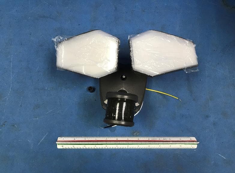
Click to zoom
Application Details
- Equipment Class
- DTS - Digital Transmission System
- Date of Grant
- Feb 19, 2022
- Application Purpose
- Original Equipment
- Date of Application
- Feb 19, 2022
- Equipment Note
- Fixed Luminaires
- Frequency Range
- 2410.00000000 - 2450.00000000
- Country
- Taiwan
Documents & Files
Document Text
Text extracted from the exhibit documents filed with the FCC. Open a document above to read the original.
Users Manual
Questions, problems, missing par ts? Bef or e ret ur ni ng to your ret ai ler , call our customer service at 1-800-887-6326 Monday – Friday 9: 00 a. m. – 5:00 p. m. CST PACKAGE CONTENTS SKU Number: 356-9448 356-9449 DUAL HEAD SECURITY LIGHT Model Number: E1205-WH E1205-BZ HARDWARE CONTENTS Note: Hardware not shown actual size. 211019 Wire Connector X3 AA CCBB DDEE Decorative cover X1 Mounting Screw X2 Mounting Strap X1 Fixture Mounting Screw X1 FF Gasket X1 A B C Before beginning assembly, installation or operation of product, make sure all parts are present. Compare parts with package contents list and diagram on previous page. If any part is missing or damaged, do not attempt to assemble, install or operate the product. Contact customer service for replacement parts. Tools Required for Assembly (not included): Slotted Screwdriver, Phillips Screwdriver, Pliers, Electrical Tape, Wire Cutters, Safety Glasses, Ladder, Wire Stripper. Please read and understand this entire manual before attempting to assemble, operate or install the product. WARNING ● Turn off electricity at main fuse box (or circuit breaker box) before beginning installation by removing fuse (or switching off circuit breaker). ● Be careful not to damage or cut the wire insulation (covering) during fixture installation. Do not permit wires to contact any surface having a sharp edge. To do so may damage or cut the wire insulation, which could cause serious injury or death from electric shock. CAUTION ● All electrical connections must be in agreement with local codes, ordinances or the national electric code (NEC). Contact your municipal building department to learn about your local codes, permits and/or inspections. ● Risk of fire – most dwellings built before 1985 have supply wire rated for 140°F/60ºC. Consult a qualified electrician before installation. ● Do not connect this fixture to an electrical system that does not provide a means for equipment grounding. Never use a fixture in a two-wire system that is not grounded. If you are not sure your lighting system has a grounding means, do not attempt to install this fixture. Contact a qualified, licensed electrician for information with regards to proper grounding methods as required by the local electrical code in your area. ● Only general ON/OFF wall switch applies for this fixture, the dimmable wall switch shouldn’t be required. Rated Wattage: 32 W Working Temperature Range: -13ºF ~ 113ºF PREPARATION SAFETY INFORMATION ASSEMBLY INSTRUCTIONS Important to Know 1. This fixture requires a 120 VAC, 60 Hz power source. 2. For general safety and to avoid any possible damage to the sensor, be sure the power is switched "off" before adjustment. 3. Motion sensor: turns light ON automatically when motion is detected and turns light down to lower level or OFF automatically when motion stops. 4. Photocell keeps the light OFF during daylight hours. Note: Fixture can be wall mounted or eave mounted. Wall Mounted Eave Mounted Light fixture and sensor should be mounted as shown above when installed (depending upon type of installation) Before installing the light fixture under an eave, the sensor head must be rotated as shown in the next two steps for proper operation and to avoid the risk of electrical shock. Page 2 of 8 211019 ASSEMBLY INSTRUCTIONS (continued) For eave mounted only: Swing the sensor head towards the mounting surface. Rotate the sensor head clockwise 180 ̊ so the controls face down. Turn off the power at fuse or circuit box. Installation Steps 1. Install the mounting strap (BB) to the outlet box with the stamped word “FRONT” facing away from the outlet box, using two mounting screws (AA) that best fit the outlet box. (Choose one matching pair of suitable mounting screws from the 3 pairs provided) 2. Connect the house grounding wire and the fixture grounding wire (green / yellow) using the wire connector (CC). Connect the fixture black wire to the house black wire and the fixture white wire to the house white wire using wire connector (CC) provided. Carefully tuck the wires back into the outlet box. Adjusting the Sensor Head: 1. a: Aim sensor head (C) toward desired detection area, maintaining a 5° - 40° downward angle to allow moisture to drain. Note: Make sure sensor head is positioned with control knob facing towards the ground. b: You can rotate the sensor head up and down to change the coverage area. (See Fig.1) 2. Note: Range set too high may increase false triggering. (See Fig.2, Fig.3) 3. Attach the backplate of the light fixture (A) to the mounting strap (BB) by secure it with the fixture mounting screw (EE). Push the decorative cover (DD) firmly into the fixture mounting screw hole on the light fixture (A). Sensor Adjustment Lower For Short Coverage Sensor Adjustment Higher For Long Coverage Fig. 2Fig. 3 1 BB AA Outlet Box 3 CC Page 3 of 8 211019 Backplate Controls 4 DD A EE BB 5 A Controls Controls 2. Thread the fixture wires through gasket (FF), and then attach the gasket (FF) into backplate of the light fixture (A). 2 A FF 5. Use silicone caulking compound (not included), caulk completely around where the backplate of the light fixture (A) meets the wall surface. CAUTION: Be sure to caulk completely where the backplate meets the wall surface to prevent water from seeping into the light fixture (A) and outlet box. Fig. 1 C Page 4 of 8 211019 ASSEMBLY INSTRUCTIONS (continued) ASSEMBLY INSTRUCTIONS (continued) Sensitivity of Motion Sensor: 1. You can adjust the sensitivity of the motion sensor by using the “Sens” selector located on the bottom surface of the sensor. (See Fig.5) 2. Adjust motion sensor sensitivity to HIGH (H), MEDIUM (M), or LOW (L) to achieve desired performance. 3. Approximate range for each setting: 30 ft. (L), 50 ft. (M), 70 ft. (H). Fig. 5 FUNCTION AND OPERATION Adjusting the Light Head: 1. Gently grasp the light heads (B) and tilt them up or down, left or right to adjust the light coverage area. Keep the light heads (B) at least 1” (25mm) a…
Text truncated - open the document above for the full version.
External Photos
External view of models E1205-WH,356-9448 External view of models E1205-BZ, 356-9449
ID Label/Location Info
FCC ID: 2AENYE1205 This device complies with Part 15 of the FCC Rules. Operation is subject to the following two conditions: (1) this device may not cause harmful interference, and (2) this device must accept any interference received, including interference that may cause undesired operation. LABEL AREA 48.5mm 22.5mm
RF Exposure Info
Intertek Testing Services Shenzhen Ltd. Guangzhou Branch Room 02, & 101/E201/E301/E401/E501/E601/E701/E801 of Room 01 1-8/F., No. 7-2. Caipin Road, Science City, GETDD, Guangzhou, Guangdong, China Job No.: 210817171G ZU FCC ID: 2AENYE1205 Version: 08 July 2020 Page 1 of 1 FCC RF Exposure-Portable RF Exposure Compliance Requirement Model no.: E1205-WH, E1205-BZ,356-9448,356-9449 The product belongs to standalone portable device base the FCC rule part 2.1091&2.1093. The transmission frequencies of the device are between 100 MHz and 6 GHz. The worst case test separation distance is 5mm. The Max Conducted Output Power and SAR Test Exclusion Threshold (mW) are listed below: Transmit frequency (GHz) Max Conducted Output Power (dBm) Max Conducted Output Power (mW) SAR Test Exclusion Threshold (mW) 2.402-2.480 -1.89 0.65 9.5 The SAR Test Exclusion Threshold is calculated from: [(max. power of channel, including tune-up tolerance, mW)/(min. test separation distance, mm)] ·[√f(GHz)] ≤ 3.0 for 1-g SAR ⚫ f(GHz) is the RF channel transmit frequency in GHz ⚫ Power and distance are rounded to the nearest mW and mm before calculation17 ⚫ The result is rounded to one decimal place for comparison According to SAR Exclusion Threshold in KDB 447498 (D01) General RF Exposure Guidance v06, the SAR report is not required. Test Location: Intertek Testing Services Shenzhen Ltd. Guangzhou Branch All tests were performed at: Room102/104, No 203, KeZhu Road, Science City, GETDD Guangzhou, China
Test Report
Luminex International Co.,Ltd TEST REPORT SCOPE OF WORK EMC TESTING–E1205-WH, 356-9448, E1205-BZ, 356-9449 REPORT NUMBER 210817171G ZU-002 ISSUE DATE [REVISED DATE] 15-February-2022 [--------------------] PAGES 39 DOCUMENT CONTROL NUMBER FCC BT 4.0-e © 2017 INTERTEK TEST REPORT Room 02, & 101/E201/E301/ E401/E501/E601/E701/E801 of Room 01 1-8/F., No. 7-2. Caipin Road, Science City, GETDD, Guangzhou, Guangdong, China Telephone: +86 20 8213 9688 Facsimile: +86 20 3205 7538 www.intertek.com.cn This report is for the exclusive use of Intertek's Client and is provide d pursuant to the agreement between Intertek and its Clien t. Intertek's responsibi lity an d liabi lity are limi ted to the terms and co ndi tions of the agreement. Intertek assumes no l iabil ity to any party, other than to the Clien t in acc ordance with the agreement, for any loss, expense or damage occasioned by the use of this report. Only the Clien t is au thorized to permit copying or d istribution of this report and then only in its e ntirety. Any use of the Intertek name or one of its marks for the sale or advertisement of the tested material, produ ct or service must f irst be a pproved in writing by Intertek. The observations and test results in th is report are relevant only to the sample teste d. This report by itself does not im ply tha t the material, product, or service is or has ever been under an Intertek certif icati on program. Intertek Testing Services Shenzhen Ltd. Guangzhou Branch Room 02, & 1 01/E201/E301/E401/E501/E601/E701/E801 of Room 01 1-8/F., No. 7-2. Caip in Road, Science Ci ty, GETDD, Guangzhou, Guangdong, China Version: 03 September 2021 Page 2 of 39 FCC BT 4.0-e Applicant Name & Address : Luminex International Co.,Ltd 5F, No. 30, Yee Shien Rd, TAIPEI CITY 110, Taiwan (Greater China) Manufacturing Site : Site1: Living Style Enterprises Limited Room 101, Building 2, No. 46, Huangtang Road, Xinsi, Hengli Town, DONGGUAN CITY, Guangdong, China Site2: Sheng Jay Automation Technologies No. 12, Wulin Street, Shulin District,NEW TAIPEI CITY 238, Taiwan(Greater China) Intertek Report No: FCC ID: 210817171GZU-002 2AENYE1205 Test standards 47 CFR PART 15 Subpart C: 2020 section 15.247 Sample Description Product : Fixed Luminaires Model No. : E1205-WH, 356-9448, E1205-BZ, 356-9449 Electrical Rating : 120VAC, 60Hz Serial No. : Not Labeled Date Received : 17 August 2021 Date Test Conducted : 27 December 2021-05 January 2022 Prepared and Checked By Elena Lei Engineer Approved By: Dean Liu Project Engineer TEST REPORT Intertek Report No.: 210817171GZU-002 Version: 03 September 2021 Page 3 of 39 FCC BT 4.0-e CONTENT TEST REPORT ....................................................................................................................1 CONTENT......................................................................................................................3 1.0 TEST RESULT SUMMARY......................................................................................4 2.0 GENERAL DESCRIPTION .......................................................................................5 2.1 PRODUCT DESCRIPTION ........................................................................................5 2.2 RELATED SUB MITTAL(S) GRANTS ..............................................................................5 2.3 TEST METH ODOLOG Y ...........................................................................................5 2.4 TEST FACILITY ....................................................................................................6 3.0 SYSTEM TEST CONFIGURATION ............................................................................6 3.1 JUSTIFICATION ...................................................................................................6 3.2 EUT EXERCISING SOFTW ARE...................................................................................7 3.3 SPECIAL ACCESSORIES...........................................................................................7 3.4 MEASUR EMEN T UNCERTAINTY ................................................................................7 3.5 EQUIPMENT MODIFICATION ...................................................................................8 3.6 SUPPORT EQUIP MEN T LIST AND DESCRIPTION...............................................................8 4.0 MEASUREMENT RESULTS ....................................................................................9 4.1 ANTEN NA REQUIREMEN T ......................................................................................9 4.2 6 DB BANDWIDTH (DTS BANDWIDTH) ..................................................................... 10 4.3 MAXIMUM PEAK CONDUCTED OUTPUT POW ER .......................................................... 13 4.4 PEAK POW ER SPECTR AL DENSITY............................................................................ 16 4.5 OUT OF BAND CONDUCTED EMISSI ONS .................................................................... 19 4.6 OUT OF BAND RADIATED EMISSI ONS ....................................................................... 22 4.7 RADIATED EMISSIONS IN RESTRICTED BANDS .............................................................. 22 4.8 BAND EDGES REQUIREMEN T................................................................................. 34 4.9 CONDUCTED EMISSION TEST................................................................................. 36 5.0 TEST EQUIPMENT LIST ...................................................................................... 39 TEST REPORT Intertek Report No.: 210817171GZU-002 Version: 03 September 2021 Page 4 of 39 FCC BT 4.0-e 1.0 TEST RESULT SUMMARY Test Item Test Requirement Test Method Result Antenna Requirement FCC PART 15 C section 15.247 (c) and Section 15.203 FCC PART 15 C section 15.247 (c) and Section 15.203 PASS 6 dB Bandwidth (DTS bandwidth) FCC PART 15 C section 15.247 (a)(2) ANSI C63.10: Clause 11.8 PASS Maximum Peak Co…
Text truncated - open the document above for the full version.
Test Setup Photos
Note:EUT is positioned at the center of the turntable to keep 3 m between the measurement antenna and EUT for the radiated emissions measurements Radiated Emission (Below 1G) Radiated Emission (Above 1GHz) Conducted Emissions at Mains Terminals
Contact Information
Applicant
Avian Dai(Manager)
Technical Contact
Intertek Testing Services Shenzhen Ltd.Guangzhou BElena Lei
[email protected]+86 20 82139616
lock E, No.7-2 Guang Dong Software Science Park, C · Guangzhou, Guangdong · China
Non-Technical Contact
Intertek Testing Services Shenzhen Ltd.Guangzhou BElena Lei
[email protected]+86 20 82139616
Test Firm
Intertek Testing Services Shenzhen LTD., GuangzhouEmily Huang
[email protected]+86 21 50319089-232
Technical Specifications
| # | Rule Parts | Frequency Range | Power Output |
|---|---|---|---|
| 1 | 15C | 2.41 GHz - 2.45 GHz | 650.00 µW |
Other Applications from Luminex International Co., Ltd
2AENY-356-1399
Dec 12, 2025Outdoor lamp
Equipment Class
DTS - Digital Transmission System
2AENYVX21110
Feb 19, 2022Fixed Luminaires
Equipment Class
DTS - Digital Transmission System
2AENYVX21301
Feb 19, 2022Fixed Luminaires
Equipment Class
DTS - Digital Transmission System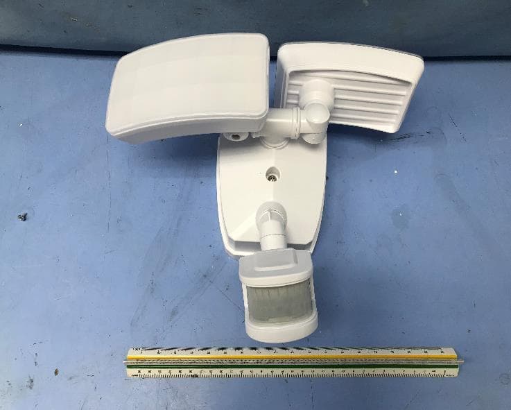
2AENYVX21111
Feb 19, 2022Fixed Luminaires
Equipment Class
DTS - Digital Transmission System
2AENY348-2128
Jul 22, 202016 LED PUFF LIGHT 3CCT SPEAKER
Equipment Class
DSS - Part 15 Spread Spectrum Transmitter