2AFDGTT-BH053V1TRUE WIRELESS STEREO EARBUDS
SUNVALLEYTEK INTERNATIONAL, INC.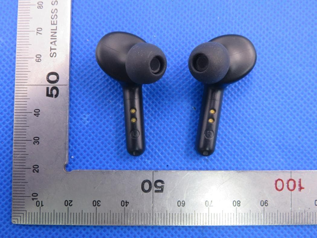
Click to zoom
Application Details
- Equipment Class
- DSS - Part 15 Spread Spectrum Transmitter
- Date of Grant
- Jan 19, 2020
- Application Purpose
- Original Equipment
- Date of Application
- Jan 19, 2020
- Equipment Note
- TRUE WIRELESS STEREO EARBUDS
- Frequency Range
- 2402.00000000 - 2480.00000000
- Country
- United States
Documents & Files
Document Text
Text extracted from the exhibit documents filed with the FCC. Open a document above to read the original.
Users Manual
MODEL: TT-BH053 TRUE WIRELESS STEREO EARBUDS User Guide 11-08-2019 TT-BH053_V2.0 EUROPE E-mail: [email protected](UK) [email protected](DE) [email protected](FR) [email protected](ES) [email protected](IT) EU Importer: ZBT International Trading GmbH Address: Halstenbeker Weg 98C, 25462 Rellingen, Deutschland NORTH AMERICA E-mail: [email protected](US) [email protected](CA) Tel: 1-888-456-8468 (Monday-Friday: 9:00 – 17:00 PST) US Distributor: SUNVALLEYTEK INTERNATIONAL INC. Address: 46724 Lakeview Blvd, Fremont, CA 94538 Manufacturer: Shenzhen NearbyExpress Technology Development Co.,Ltd. Address: 333 Bulong Road, Shenzhen, China, 518129 MANUFACTURER ASIA PACIFIC E-mail: [email protected](JP) www.taotronics.com MADE IN CHINA LR Learn more about the EU Declaration of Conformity: https://www.taotronics.com/downloads-TT-BH053-CE-Cert.html FCC ID: 2AFDGTT-BH053V1 CONTENTS English Deutsch Français Español Italiano 01-11 12-23 24-36 37-49 50-62 63-74 PACKAGE CONTENTS (Fig. 1) TaoTronics True Wireless Stereo Earbuds (TT-BH053) 8 x Ear Tips (two are equipped on the earbuds) 1 x USB Charging Cable 1 x User Manual 1 x Quick Start Guide EN LR 1 Taotronics True Wireless Stereo-Kopfhörer (TT-BH053) 8 x Ohrstöpsel (zwei sind bereits an den Ohrhörern angebracht) 1 x USB-Ladekabel 1 x Bedienungsanleitung 1 x Schnellstart-Anleitung DE Écouteurs Stéréo Entièrement Sans Fil TaoTronics (TT-BH053) 8 x Embouts d’Oreillette (deux sont déjà installés sur les écouteurs) 1 x Câble de Charge USB 1 x Manuel de l'Utilisateur 1 x Guide de Démarrage Rapide FR Auriculares Inalámbricos Estéreo TaoTronics (TT-BH053) 8 x Puntas de Goma para Oídos (dos están equipados en los auriculares) 1 x Cable de Carga USB 1 x Manual de Usuario 1 x Guía de Inicio Rápido ES Auricolari Stereo True Wireless Stereo TaoTronics (TT-BH053) 8 Puntali Auricolari (due già montati sugli auricolari) 1 x Cavo di Ricarica USB 1 x Manuale Utente 1 Manuale di Avvio Rapido IT JP MODEL: TT-BH053 TAOTRONICS SOUNDLIBERTY 53 TRUE WIRELESS STEREO EARBUDS User Guide LR LR MODEL: TT-BH053 TAOTRONICS SOUNDLIBERTY 53 TRUE WIRELESS STEREO EARBUDS Quick Start Guide PRODUCT DIAGRAM (Fig. 2) 2 Multifunction Touch Control LED Indicator Microphone Charging Contacts Micro USB Charging Port Charging Case Charging Indicator Charging Slot EN Multifunktions-Touch-Steuerung LED-Anzeige Mikrofon Ladekontakte Micro-USB-Ladeanschluss Ladehülle Ladeanzeige Ladeschacht DE Multifonction Touche Tactile Voyant à LED Micro Contacts de Charge Port de Charge Micro-USB Boîtier de Charge Voyant de Charge Slot de Charge FR Control Táctil Multifunción Indicador LED Micrófono Contactos de Carga Puerto de Carga Micro USB Estuche de Carga Indicador de Carga Ranura de Carga ES Controllo Touch Multifunzione Indicatore LED Microfono Contatti per la Ricarica Porta di Ricarica Micro USB Custodia per la Ricarica Indicatore di Ricarica Slot per la Ricarica IT タッチコントロール JP 0102 EN IMPORTANT SAFETY INSTRUCTIONS Please read the instructions thoroughly before using this product and retain it for future reference. Hearing Safety • Do not wear earbuds with high volume for a long time to avoid damaging your hearing. • Set the earbuds to low volume before you put them on, then increase the volume gradually as per your preference. • Do not set volume too high to stay aware of your surroundings. • Please refer to local laws and regulations if you want to answer phone calls via this device during driving. • For your safety, avoid distraction from music or phone calls when you are driving or doing other activities with potential dangers. Warning: Please set the volume to proper level to avoid hearing damages. Caution • Do not expose this product to high temperatures. • Do not immerse the earbuds into water or expose them to humidity for a long time. • Do not clean the product with detergent containing alcohol, ammonia, benzene or abrasives. • Avoid dropping. • Place the earbuds back into the charging case when not in use and keep it away from children and pets to avoid choking hazard. • Unauthorized disassembly of any parts of this product is forbidden, which may cause fire hazard, warranty voidance, and/or property loss. • Close attention is needed when using near children. • Keep the charging case away from water, rain or any other liquid. • Don’t use the product in thunderstorm to avoid malfunction or electric shock. • Always ask a professional technician or authorized personnel for repair. This product contains lithium battery. Never expose it to excessive heat such as direct sunlight or fire to avoid explosion. HOW TO WEAR Choose the Right Tips (Fig. 3) Ear tips with different sizes are included in the package, try all sizes and choose the ones fitting you best. 3 0304 Wear the Earbuds (Fig. 4) Please wear the earbuds as shown below. 4 ①②③ Pictures only for reference. Bluetooth Caution • When the device is connected wirelessly to another device, place the two devices close to each other to achieve their normal functionalities and avoid possible signal interference. • The maximum effective Bluetooth range is 10 meters (33 feet), which may vary with the environmental circumstances. • When using a wireless connection, make sure there are no obstacles between the two devices. Obstacles including walls and fences may shorten the effective range. USING YOUR EARBUDS Charging Charging the Earbuds 1. Put the earbuds into the charging case as per the L (left) and R (right) marks (Fig. 5). 2. Charging will start automatically. The LED indicator will flash blue slowly when charging and turn off when charging is completed (Fig. 6). Note: • Put the earbuds into the charging case, the charging indicator on the charging case will be on for 5 seconds to show the current battery level then turn off. • Please fully charge the earbuds when using them for the first time. • When battery is low, a “Battery low” voice prompt will be heard (if you are wearing the earbud…
Text truncated - open the document above for the full version.
Cover Letter(s)
SUNVALLEYTEK INTERNATIONAL, INC. 46724 Lakeview Blvd, Fremont, CA 94538-6529 [Jan. 7, 2020] Federal Communications Commission 445 12 th Street SW Washington, DC 20554 Subject: Limited Agency Agreement SUNVALLEYTEK INTERNATIONAL, INC. FCC ID: 2AFDGTT-BH053V1 To Whom It May Concern: We, SUNVALLEYTEK INTERNATIONAL, INC. hereby authorized Intertek Testing Services to act as our Agent for the purpose of preparing application for FCC ID number (2AFDGTT- BH053V1) under all applicable parts of the FCC rules and regulations. The effective date of this limited agency agreement is (2020-01-07). The Limited Agency Agreement expires until further notice, unless sooner terminated or extended by written notice to Intertek Testing Services and the Federal Communications Commission. This is to advise that we are in full compliance with the Anti-Drug Abuse Act. The applicant is not subject to a denial of federal benefits pursuant to Section 5301 of the Anti-Drug Act of 1988, 21 U.S.C. 862, and no party to the application is subject to a denial of federal benefits pursuant to that section. If you have any questions or comments, please do not hesitate to contact me. Sincerely, [Signature] SUNVALLEYTEK INTERNATIONAL, INC. Contact person: kent peng Title: General Manager
External Photos
External Photos Test Model: TT-BH053 TOTAL VIEW OF EUT Headset TOP VIEW OF EUT BOTTOM VIEW OF EUT FRONT VIEW OF EUT BACK VIEW OF EUT LEFT VIEW OF EUT RIGHT VIEW OF EUT VIEW OF EUT (Port) Charging Dock TOP VIEW OF EUT BOTTOM VIEW OF EUT FRONT VIEW OF EUT BACK VIEW OF EUT LEFT VIEW OF EUT RIGHT VIEW OF EUT VIEW OF EUT (Port)-1 VIEW OF EUT (Port)-2
ID Label/Location Info
SOUNDLIBERTY 53 True Wireless Stereo Earbuds TT-BH053 FCC ID:2AFDGTT-BH053V1 Technology Enhances Life www.taotronics.com UV SOUNDLIBERTY 53 TT-BH053 110X89X39 mm PANTONE ORANGE 021C SOUNDLIBERTY 53 TRUE WIRELESS STEREO EARBUDS This device complies with Part 15 of the FCC Rules. Operation is subject to the following two conditions: (1) this device may not cause harmful interference, and (2) this device must accept any interference received, including interference that may cause undesired operation.
Internal Photos
Internal Photos Test Model: TT-BH053 Right OPEN VIEW OF EUT VIEW OF BATTERY INTERNAL VIEW OF EUT-1 INTERNAL VIEW OF EUT-2 INTERNAL VIEW OF EUT-3 INTERNAL VIEW OF EUT-4 BT Antenna Left OPEN VIEW OF EUT VIEW OF BATTERY INTERNAL VIEW OF EUT-1 INTERNAL VIEW OF EUT-2 INTERNAL VIEW OF EUT-3 INTERNAL VIEW OF EUT-4 BT Antenna Charging Dock OPEN VIEW OF EUT VIEW OF BATTERY INTERNAL VIEW OF EUT-1 INTERNAL VIEW OF EUT-2 INTERNAL VIEW OF EUT-3 INTERNAL VIEW OF EUT-4
RF Exposure Info
RF EXPOSURE EVALUATION 1. PRODUCT INFORMATION Product Description TRUE WIRELESS STEREO EARBUDS Model Name TT-BH053 FCC ID 2AFDGTT-BH053V1 2. EVALUATION METHOD According to 447498 D01 General RF Exposure Guidance v05 The 1-g and 10-g SAR test exclusion thresholds for 100 MHz to 6 GHz at test separation distances ≤ 50 mm are determined by: [(max. power of channel, including tune-up tolerance, mW)/(min. test separation distance, mm)] ·[√f(GHz)] ≤ 3.0 for 1-g SAR and ≤ 7.5 for 10-g extremity SAR. Where f(GHz) is the RF channel transmit frequency in GHz Power and distance are rounded to the nearest mW and mm before calculation 3. CALCULATION P t =2.715dBm=1.87mW The value of the Maximum output power P t is referred to the test report of the CFR47 §15.247. The result for RF exposure evaluation SAR=(1.87mW /5mm) .[√2.480(GHz)]= 0.59<3.0 for 1-g SAR and ≤ 7.5 for 10-g extremity SAR. 4. CONCLUSION The SAR evaluation is not required.
Test Report
Page 1 of 76 FCC Test Report Report No.: AGC00210191202FE03 FCC ID : 2AFDGTT-BH053V1 APPLICATION PURPOSE : Original Equipment PRODUCT DESIGNATION : TRUE WIRELESS STEREO EARBUDS BRAND NAME : TAOTRONICS MODEL NAME : TT-BH053 APPLICANT : SUNVALLEYTEK INTERNATIONAL, INC. DATE OF ISSUE : Jan. 02, 2020 STANDARD(S) : FCC Part 15.247 REPORT VERSION : V1.0 Attestation of Global Compliance (Shenzhen) Co., Ltd CAUTION: This report shall not be reproduced except in full without the written permission of the test laboratory and shall not be quoted out of context. Report No.: AGC00210191202FE03 Page 2 of 76 REPORT REVISE RECORD Report Version Revise Time Issued Date Valid Version Notes V1.0 / Jan. 02, 2020 Valid Initial Release Report No.: AGC00210191202FE03 Page 3 of 76 TABLE OF CONTENTS 1. VERIFICATION OF CONFORMITY .............................................................................................................. 5 2. GENERAL INFORMATION .......................................................................................................................... 6 2.1. PRODUCT DESCRIPTION .................................................................................................................... 6 2.2. TABLE OF CARRIER FREQUENCYS .................................................................................................... 6 2.3. RECEIVER INPUT BANDWIDTH ........................................................................................................... 7 2.4. EXAMPLE OF A HOPPING SEQUENCY IN DATA MODE ....................................................................... 7 2.5. EQUALLY AVERAGE USE OF FREQUENCIES AND BEHAVIOUR ........................................................ 7 2.6. RELATED SUBMITTAL(S) / GRANT (S) ................................................................................................. 8 2.7. TEST METHODOLOGY ......................................................................................................................... 8 2.8. SPECIAL ACCESSORIES ..................................................................................................................... 8 2.9. EQUIPMENT MODIFICATIONS ............................................................................................................. 8 3. MEASUREMENT UNCERTAINTY ............................................................................................................... 9 4. DESCRIPTION OF TEST MODES ............................................................................................................. 10 5. SYSTEM TEST CONFIGURATION ............................................................................................................ 11 5.1. CONFIGURATION OF EUT SYSTEM .................................................................................................. 11 5.2. EQUIPMENT USED IN TESTED SYSTEM .......................................................................................... 11 5.3. SUMMARY OF TEST RESULTS .......................................................................................................... 11 6. TEST FACILITY ......................................................................................................................................... 12 7. PEAK OUTPUT POWER ........................................................................................................................... 13 7.1. MEASUREMENT PROCEDURE.......................................................................................................... 13 7.2. TEST SET-UP (BLOCK DIAGRAM OF CONFIGURATION) .................................................................. 13 7.3. LIMITS AND MEASUREMENT RESULT .............................................................................................. 14 8. 20DB BANDWIDTH ................................................................................................................................... 20 8.1. MEASUREMENT PROCEDURE.......................................................................................................... 20 8.2. TEST SET-UP (BLOCK DIAGRAM OF CONFIGURATION) .................................................................. 20 8.3. LIMITS AND MEASUREMENT RESULTS ............................................................................................ 20 9. CONDUCTED SPURIOUS EMISSION ....................................................................................................... 27 9.1. MEASUREMENT PROCEDURE.......................................................................................................... 27 9.2. TEST SET-UP (BLOCK DIAGRAM OF CONFIGURATION) .................................................................. 27 9.3. MEASUREMENT EQUIPMENT USED ................................................................................................. 27 9.4. LIMITS AND MEASUREMENT RESULT .............................................................................................. 27 Report No.: AGC00210191202FE03 Page 4 of 76 10. RADIATED EMISSION ............................................................................................................................. 37 10.1. MEASUREMENT PROCEDURE ........................................................................................................ 37 10.2. TEST SETUP ..................................................................................................................................... 39 10.3. LIMITS AND MEASUREMENT RESULT ............................................................................................ 40 10.4. TEST RESULT ................................................................................................................................... 40 11. NUMBER OF HOPPING FREQUENCY .................................................................................................... 50 11.1. MEASUREMENT PROCEDURE .......................................…
Text truncated - open the document above for the full version.
Test Report
Report No.: AGC00210191202FE03 Page 51 of 76 12. TIME OF OCCUPANCY (DWELL TIME) 12.1. MEASUREMENT PROCEDURE The EUT shall have its hopping function enabled. Use the following spectrum analyzer settings: 1. Span: Zero span, centered on a hopping channel. 2. RBW shall be≤channel spacing and where possible RBW should be set >> 1 / T, where T is the expected dwell time per channel. 3. Sweep: As necessary to capture the entire dwell time per hopping channel; where possible use a video trigger and trigger delay so that the transmitted signal starts a little to the right of the start of the plot. The trigger level might need slight adjustment to prevent triggering when the system hops on an adjacent channel; a second plot might be needed with a longer sweep time to show two successive hops on a channel. 4. Detector function: Peak. Trace: Max hold. 5. Use the marker-delta function to determine the transmit time per hop. 6. Repeat the measurement using a longer sweep time to determine the number of hops over the period specified in the requirements. The sweep time shall be equal to, or less than, the period specified in the requirements. Determine the number of hops over the sweep time and calculate the total number of hops in the period specified in the requirements, using the following equation: (Number of hops in the period specified in the requirements) = (number of hops on spectrum analyzer) × (period specified in the requirements / analyzer sweep time) 7. The average time of occupancy is calculated from the transmit time per hop multiplied by the number of hops in the period specified in the requirements. 12.2. TEST SETUP (BLOCK DIAGRAM OF CONFIGURATION) Same as described in section 8.2 12.3. MEASUREMENT EQUIPMENT USED The same as described in section 6 12.4. LIMITS AND MEASUREMENT RESULT Channel Time of Pulse for DH5 (ms) Number of hops in the period specified in the requirements Sweep Time (ms) Limit (ms) Low 2.883 26*4 299.832 400 Middle 2.883 26*4 299.832 400 High 2.900 27*4 313.200 400 Note: The 8DPSK modulation is the worst case and recorded in the report. Report No.: AGC00210191202FE03 Page 52 of 76 TEST PLOT OF LOW CHANNEL Report No.: AGC00210191202FE03 Page 53 of 76 TEST PLOT OF MIDDLE CHANNEL Report No.: AGC00210191202FE03 Page 54 of 76 TEST PLOT OF HIGH CHANNEL Report No.: AGC00210191202FE03 Page 55 of 76 13. FREQUENCY SEPARATION 13.1. MEASUREMENT PROCEDURE The EUT shall have its hopping function enabled. Use the following spectrum analyzer settings: 1. Span: Wide enough to capture the peaks of two adjacent channels. 2. RBW: Start with the RBW set to approximately 30% of the channel spacing; adjust as necessary to best identify the center of each individual channel. 3. Video (or average) bandwidth (VBW) ≥ RBW. 4. Sweep: Auto. e) Detector function: Peak. f) Trace: Max hold. g) Allow the trace to stabilize. Use the marker-delta function to determine the separation between the peaks of the adjacent channels. 13.2. TEST SETUP (BLOCK DIAGRAM OF CONFIGURATION) Same as described in section 6.2 13.3. MEASUREMENT EQUIPMENT USED The same as described in section 6.3 13.4. LIMITS AND MEASUREMENT RESULT CHANNEL CHANNEL SEPARATION KHz LIMIT (KHz) RESULT CH01-CH02 1000 >=25 KHz or 2/3 20 dB BW PASS TEST PLOT FOR FREQUENCY SEPARATION Note: The 8DPSK modulation is the worst case and recorded in the report. Report No.: AGC00210191202FE03 Page 56 of 76 14. FCC LINE CONDUCTED EMISSION TEST 14.1. LIMITS OF LINE CONDUCTED EMISSION TEST Frequency Maximum RF Line Voltage Q.P.( dBuV) Average( dBuV) 150kHz~500kHz 66-56 56-46 500kHz~5MHz 56 46 5MHz~30MHz 60 50 Note: 1. The lower limit shall apply at the transition frequency. 2. The limit decreases linearly with the logarithm of the frequency in the range 0.15 MHz to 0.50 MHz. 14.2. BLOCK DIAGRAM OF LINE CONDUCTED EMISSION TEST EUT & Support Units Report No.: AGC00210191202FE03 Page 57 of 76 14.3. PRELIMINARY PROCEDURE OF LINE CONDUCTED EMISSION TEST 1. The equipment was set up as per the test configuration to simulate typical actual usage per the user’s manual. When the EUT is a tabletop system, a wooden table with a height of 0.8 meters is used and is placed on the ground plane as per ANSI C63.10 (see Test Facility for the dimensions of the ground plane used). When the EUT is a floor-standing equipment, it is placed on the ground plane which has a 3-12 mm non-conductive covering to insulate the EUT from the ground plane. 2. Support equipment, if needed, was placed as per ANSI C63.10. 3. All I/O cables were positioned to simulate typical actual usage as per ANSI C63.10. 4. All support equipments received AC120V/60Hz power from a LISN, if any. 5. The EUT received DC charging voltage by adapter which received AC120V/60Hz power by a LISN. 6. The test program was started. Emissions were measured on each current carrying line of the EUT using a spectrum Analyzer / Receiver connected to the LISN powering the EUT. The LISN has two monitoring points: Line 1 (Hot Side) and Line 2 (Neutral Side). Two scans were taken: one with Line 1 connected to Analyzer / Receiver and Line 2 connected to a 50 ohm load; the second scan had Line 1 connected to a 50 ohm load and Line 2 connected to the Analyzer / Receiver. 7. Analyzer / Receiver scanned from 150 kHz to 30MHz for emissions in each of the test modes. 8. During the above scans, the emissions were maximized by cable manipulation. 9. The test mode(s) were scanned during the preliminary test. Then, the EUT configuration and cable configuration of the above highest emission level were recorded for reference of final testing. 14.4. FINAL PROCEDURE OF LINE CONDUCTED EMISSION TEST 1. EUT and support equipment was set up on the test bench as per step 2 of the preliminary test. 2. A scan was taken on both power lines, Line 1 and Line 2, recording at least the six highest emissions. Emission frequency and amplitude were recorded into a computer in which correction factors were used to calculate the emission level and compare read…
Text truncated - open the document above for the full version.
Contact Information
Applicant
kent peng
Technical Contact
Attestation of Global Compliance (Shenzhen) Co., LYimi Zhao
[email protected]86-755-29081977
2F.,No.2 Building, Huafeng No.1 Technical Industri · Shenzhen · China
Test Firm
Attestation of Global Compliance (Shenzhen) Co., LDoris Li
[email protected]+86-755-25234088
Technical Specifications
| # | Rule Parts | Frequency Range | Power Output |
|---|---|---|---|
| 1 | 15C | 2.40 GHz - 2.48 GHz | 1.87 mW |
Other Applications from SUNVALLEYTEK INTERNATIONAL, INC.
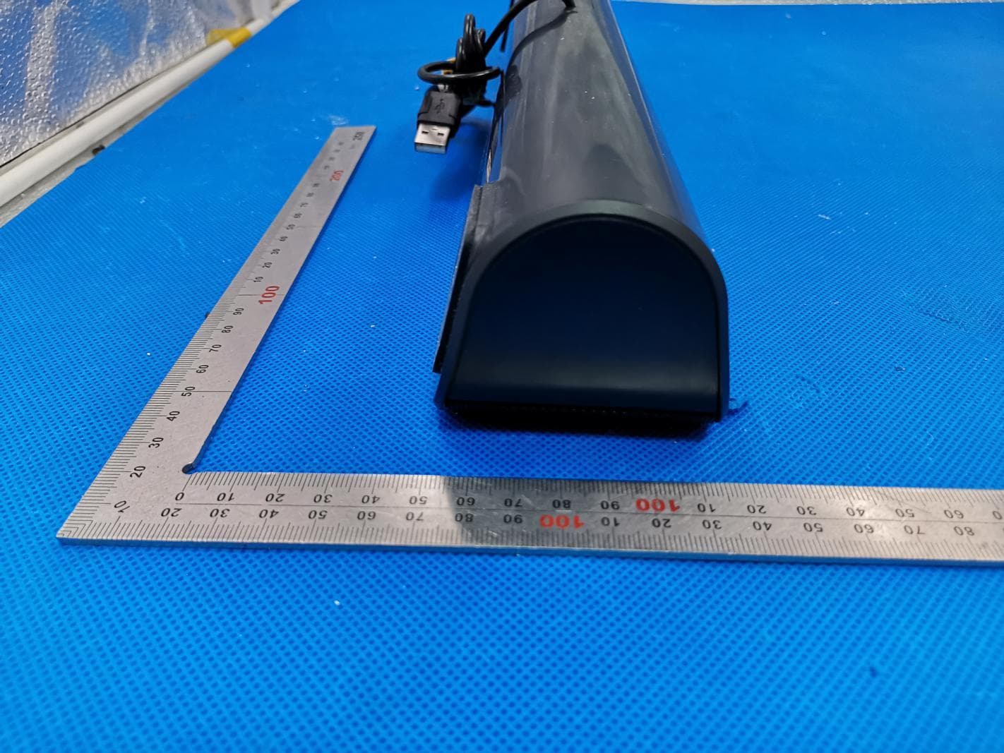
2AFDGTT-SK028
May 04, 2020PC Sound Bar
Equipment Class
DSS - Part 15 Spread Spectrum Transmitter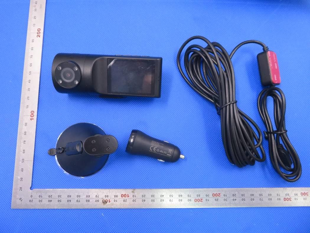
2AFDGVA-VD009
Apr 08, 2020VAVA 2K DUAL DASH CAM
Equipment Class
DTS - Digital Transmission System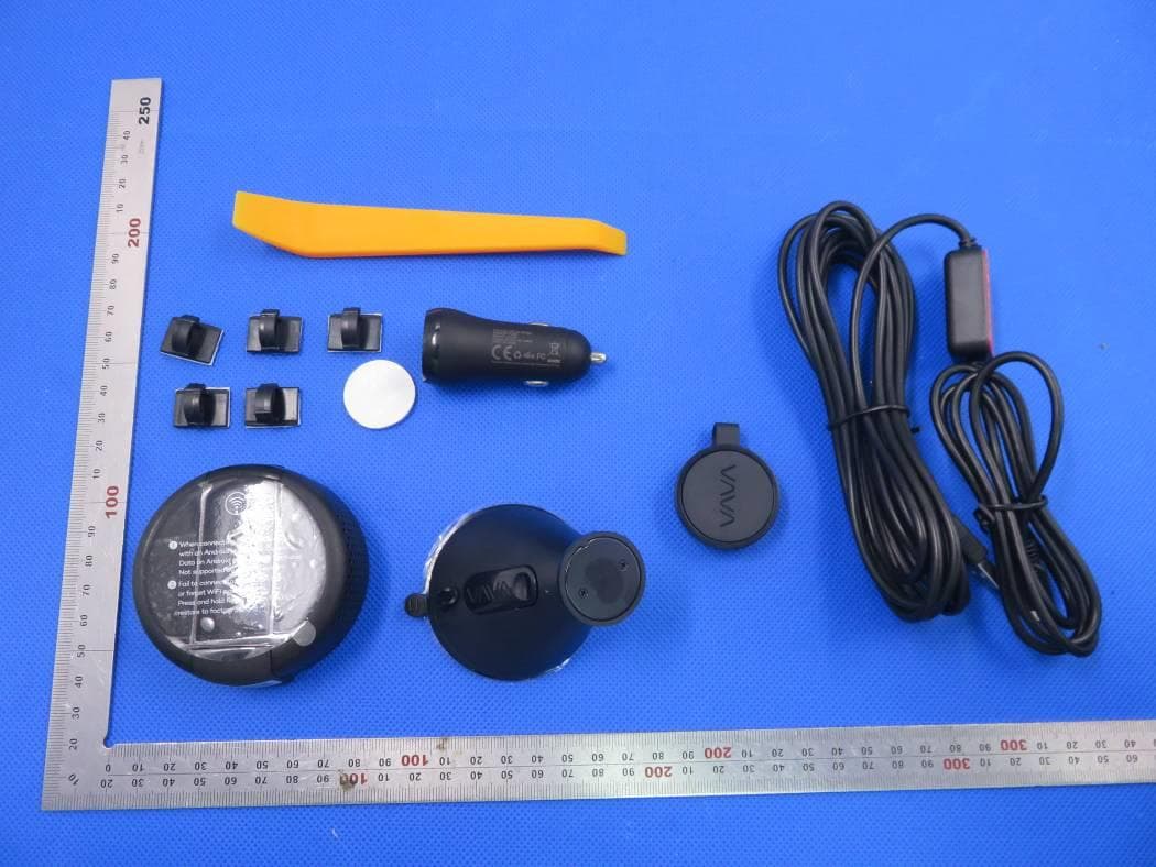
2AFDGVA-VD004V1
Apr 07, 2020DASH CAM
Equipment Class
DTS - Digital Transmission System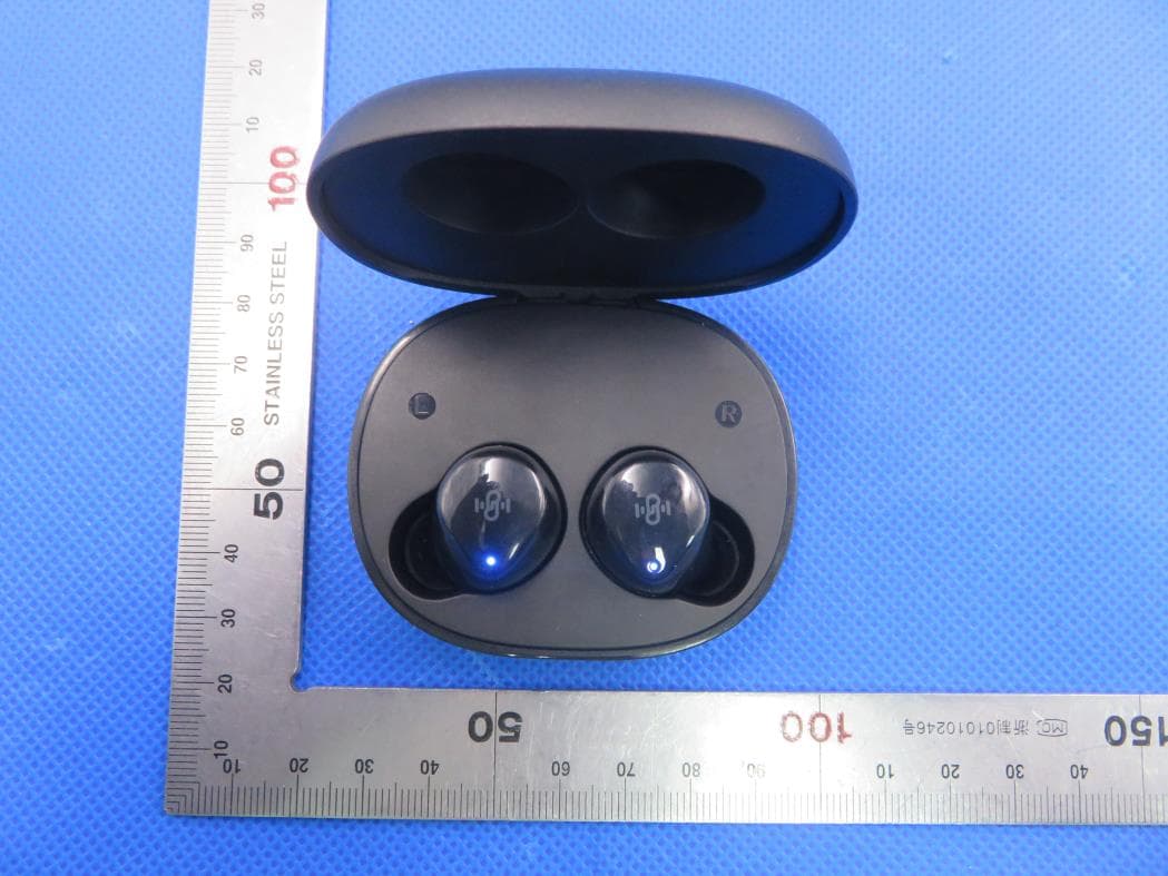
2AFDGBT-BH021
Jan 08, 2020TRUE WIRELESS STEREO EARBUDS
Equipment Class
DSS - Part 15 Spread Spectrum Transmitter