2AFDGVA-VD004V1DASH CAM
SUNVALLEYTEK INTERNATIONAL, INC.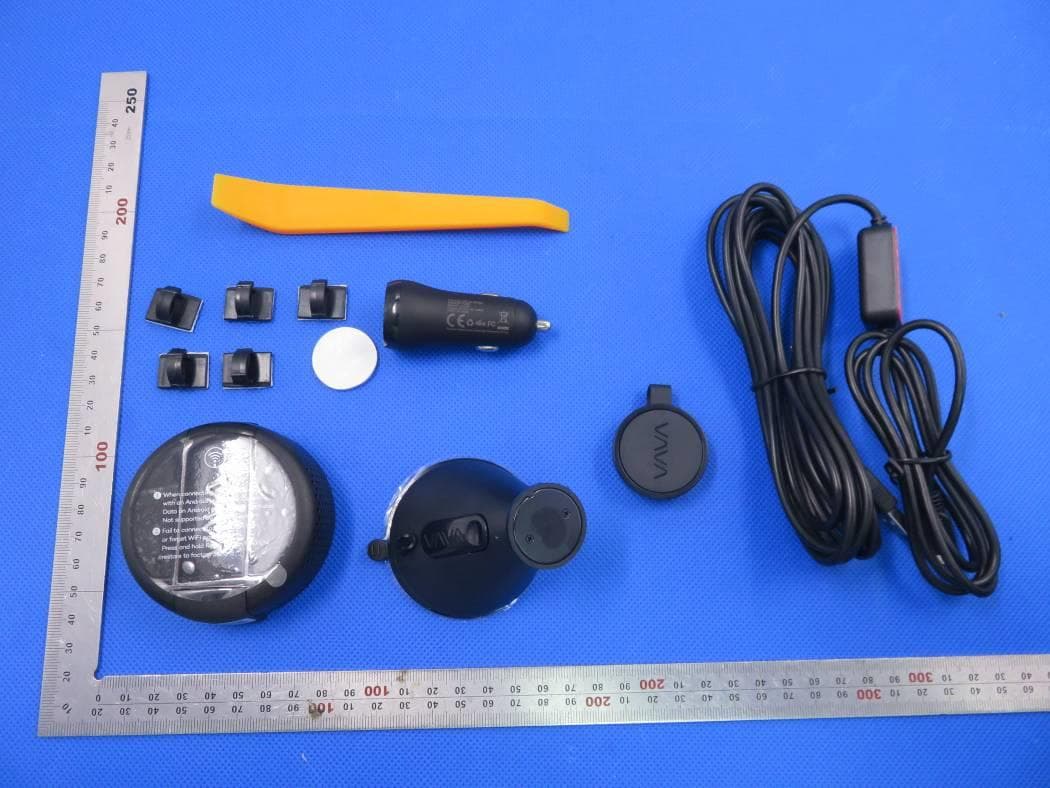
Click to zoom
Application Details
- Equipment Class
- DTS - Digital Transmission System
- Date of Grant
- Apr 07, 2020
- Application Purpose
- Original Equipment
- Date of Application
- Apr 07, 2020
- Equipment Note
- DASH CAM
- Frequency Range
- 2412.00000000 - 2462.00000000
- Country
- United States
Documents & Files
Document Text
Text extracted from the exhibit documents filed with the FCC. Open a document above to read the original.
Users Manual
尺寸:128*70mm 骑马钉 材质:封面128克铜版纸过哑油 内页80克书纸 DASH CAM USER MANUAL Please read this manual before operating your device and keep it for future reference. VA-VD004_V1.4 www.vava.com E-mail: [email protected] Tel: 1-888-456-8468 (Monday-Friday: 9:00 – 17:00 PST) US Distributor: SUNVALLEYTEK INTERNATIONAL INC. Address: 46724 Lakeview Blvd, Fremont, CA 94538 NORTH AMERICA EUROPE E-mail: [email protected](UK) [email protected](DE) [email protected](FR) [email protected](ES) [email protected](IT) EU Importer: ZBT International Trading GmbH Address: Halstenbeker Weg 98C, 25462 Rellingen, Deutschland Learn more about the EU Declaration of Conformity: https://www.vava.com/downloads-VA-VD004-CE-Cert.html MANUFACTURER Shenzhen NearbyExpress Technology Development Co.,Ltd. Address: 333 Bulong Road, Shenzhen, China, 518129 ASIA PACIFIC E-mail: [email protected](JP) Te l: 03-5542-023810-18/ JP Importer: SUNVALLEY JAPAN Address: 104-0032 18-6 PMOF MADE IN CHINA What’s in the Box VAVA Dash CamMountCar ChargerSnapshot Button Charging CableCrowbarCable ClipsUser Manual Note: The package contents may vary according to different orders. Product Diagram 01/02 1. Car Mount 2. Micro USB Port 3. Power / Working Status LED 4. WiFi Status LED 5. Reset Button 6. Micro SD Card Slot MODEL: VA VD004 DASH CAM USER MANUAL Please read this manual before operating your device and keep it for future reference. 03/04 Product Specifications Memory Card Installation Note: 1. Don’t install or remove the Micro SD card when the Dash Cam is powered on to avoid breakage of the card. 2. Please format the Micro SD card regularly for a better user experience. Remember to backup your f iles before formatting the memory card.. For reliable operation, please use a U3 microSD/TF card with a capacity of 16GB, 32GB, 64GB, 128GB or 256GB. Brands RecommendedSandisk / Samsung Insert a card with the gold contacts facing down. Push the card until it clicks into place. To remove the card, gently push it until it clicks and pull it out of the slot. CPU Camera Sensor Lens (FOV) Video Resolution G-sensor Video Clip / Photo Format Wireless Connections Power Input Built-in Battery Capacity Operating Temperature H22A55 Sony IMX317 4G + 2P +1 IR Lens(135°) 3840*2160/30fps 2560*1440/30fps 1920*1080/60fps 1920*1080/30fps 3-axis Accelerometer MP4 / JPG Wi-Fi (between smart phone and Dash Cam) 2.4G (between Snapshot Button and Dash Cam) 5V / 1A 320mAh -20°C to 50°C/-4°F to 122°F 05/06 Dash Cam Installation 1. Insert the micro SD card into the micro SD card slot. 2. Stick the car mount onto your car windshield (ideally right in the middle). 3. Fix the VAVA Dash Cam onto the mount via the magnet. 4. Connect the USB cable to the micro USB port of the dash cam. Run the cable along the edge of the windshield, tuck it away in the seams, and extend it all the way to the USB port of the Car Charger. Be sure to keep it away from the airbag area. 5. Insert the Car Charger into your cigarette lighter, connect the Dash Cam to the Car Charger. 6. Start your car to turn on the VAVA Dash Cam. Connect it with your phone (refer to the “VAVA Dash App” section) and open the VAVA Dash App to view a real-time feed. ① ② Ideal Mounting Position Car Charger Note: · Do not remove or insert the micro SD card when the camera is working. · Do not use the Car Charger to charge devices with Quick Charge technology. · Install the car mount on windshields that are tilted on an angle between 17° - 58°. 07/08 Snapshot Button NoteThe Snapshot Button enters standby mode once there is no operation for 1 minute. Press again to restart and take a photo. Dash Cam and Snapshot Button Pairing Dash Cam and Snapshot Button Pairing: Once the Dash Cam is turned on, press and hold the Snapshot Button for 5 -30 seconds until you hear 4 beep sounds. This means that they are synced. Installing the Snapshot Button Install the Snapshot Button onto the steering wheel with the 3M sticker. Attach it to your key chains if needed. Using the Snapshot Button Taking photos: Press once to take photos Taking short videos: Press and hold for 3 seconds until you hear a beep to take videos. VAVA Dash Cam App Download Please search ‘VAVA Dash’ in App Store or Google Play to download the App. Note: Systems supported: Android 4.4 and above / iOS 8.0 and above. Connect Dash Cam with Smartphone 1. Turn on Wi-Fi on your phone 2. Find “VAVA_XXXXXXXXXXXX” in the Wi-Fi list and connect to it, enter the password (initial password: 12345678). 3. Open VAVA Dash App and follow the instructions to complete the connection. Replacing the battery: Batterry ModelLithium Battery CR 2032 3V Replace the battery: Open the Snapshot Button and put the battery inside with the right polarities. 09/10 Using Your VAVA Dash Cam LED Indicator Information LED Indicator Blue LED light slowly blinks Blue LED light solid on Red LED light blinks Red LED light solid on Red LED light flashes once White LED light on White LED light off Blue LED light and red LED light solid on Dash Cam Status Working Stopped working Recording an emergency video clip / a manual video clip taken via the app or Snapshot Button / micro SD card not inserted Micro SD card error / micro SD card storage full Taking a photo by app or Snapshot Button Mobile phone connected to Wi-Fi Mobile phone disconnected from Wi-Fi The Dash Cam has crashed Red LED light solid onPlease install the Micro SD card properly to ensure its functionality and format it via the App. Blue LED light and red LED light solid onPlease reset the Dash Cam. Videos and Photos / Media Gallery Videos Automatic Recording: Video recording is automatically activated once the car is started. Manual Recording: A default 20-second video footage will be recorded through the app or the Snapshot Button. Emergency Recording: A video footage is generated once a collision or bump is detected through the G-sensor during driving or in parking monitor mode. Photos The photos can be taken via the Snapshot Button or you can tap …
Text truncated - open the document above for the full version.
Cover Letter(s)
SUNVALLEYTEK INTERNATIONAL, INC. 46724 Lakeview Blvd, Fremont, CA 94538-6529 [Mar. 25, 2020] Federal Communications Commission 445 12 th Street SW Washington, DC 20554 Subject: Limited Agency Agreement SUNVALLEYTEK INTERNATIONAL, INC. FCC ID: 2AFDGVA-VD004V1 To Whom It May Concern: We, SUNVALLEYTEK INTERNATIONAL, INC. hereby authorized Intertek Testing Services to act as our Agent for the purpose of preparing application for FCC ID number (2AFDGVA- VD004V1) under all applicable parts of the FCC rules and regulations. The effective date of this limited agency agreement is (2020-03-25). The Limited Agency Agreement expires until further notice, unless sooner terminated or extended by written notice to Intertek Testing Services and the Federal Communications Commission. This is to advise that we are in full compliance with the Anti-Drug Abuse Act. The applicant is not subject to a denial of federal benefits pursuant to Section 5301 of the Anti-Drug Act of 1988, 21 U.S.C. 862, and no party to the application is subject to a denial of federal benefits pursuant to that section. If you have any questions or comments, please do not hesitate to contact me. Sincerely, [Signature] SUNVALLEYTEK INTERNATIONAL, INC. Contact person: kent peng Title: General Manager
Cover Letter(s)
SUNVALLEYTEK INTERNATIONAL, INC. 46724 Lakeview Blvd, Fremont, CA 94538-6529 Mar. 25, 2020 Federal Communication Commission Authorization and Evaluation Division FCC ID: 2AFDGVA-VD004V1 Re: Confidentiality Request Pursuant to Sections 0.457 and 0.459 of the Commission’s Rules, the applicant hereby requests confidential treatment of information applied this application as outlined below: 1: Block Diagram 2: Schematics 3: Operational Description The above materials contain trade secrets and proprietary information not customarily released to the public. The public disclosure of these matters might be harmful to the applicant and provide unjustified benefits to its competitors. The Applicant understands that pursuant to Rules 0.457, disclosure of this Application and all accompanying documentation will not be made before the date of the Grant for this application. Sincerely, SUNVALLEYTEK INTERNATIONAL, INC. Contact person: kent peng Title: General Manager
External Photos
External Photos Test Model: VA-VD004 ALL VIEW OF EUT TOP VIEW OF EUT BOTTOM VIEW OF EUT FRONT VIEW OF EUT BACK VIEW OF EUT LEFT VIEW OF EUT RIGHT VIEW OF EUT VIEW OF EUT(PORT)-1 VIEW OF EUT(PORT)-2
ID Label/Location Info
FCC ID Label Location 10mm*40mm FCC ID: 2AFDGVA-VD004V1
Internal Photos
Internal Photos Test Model: VA-VD004 OPEN VIEW OF EUT-1 OPEN VIEW OF EUT-2 OPEN VIEW OF EUT-3 INTERNAL VIEW-1 OF EUT BT/WIFI Antenna INTERNAL VIEW-2 OF EUT INTERNAL VIEW-3 OF EUT INTERNAL VIEW-4 OF EUT INTERNAL VIEW-5 OF EUT INTERNAL VIEW-6 OF EUT INTERNAL VIEW-7 OF EUT INTERNAL VIEW-8 OF EUT INTERNAL VIEW-9 OF EUT VIEW OF BATTERY
RF Exposure Info
RF EXPOSURE EVALUATION 1. PRODUCT INFORMATION Product Description DASH CAM Model Name VA-VD004 FCC ID 2AFDGVA-VD004V1 2. EVALUATION METHOD AND LIMIT Human exposure to RF emissions from mobile devices (47 CFR §2.1091) may be evaluated based on the MPE limits adopted by the FCC for electric and magnetic field strength and/or power density, as appropriate, since exposures are assumed to occur at distances of 20 cm or more from persons. LIMITS FOR GENERAL POPULATION / UNCONTROLLED EXPOSURE Frequency Range (MHz) E-field Strength (E) (V/m) Magnetic Field Strength (H) (A/m) Power Density (S) (mW/cm 2 ) Averaging Time |E| 2 , |H| 2 or S (Minutes) 0.3 -- 1.34 614 1.63 (100)* 30 1.34 -- 30 824/f 2.19/f (180/f 2 )* 30 30 -- 300 27.5 0.073 0.2 30 300 -- 1500 -- -- f/1500 30 1500 -- 100,000 -- -- 1.0 30 *Note: 1. f= Frequency in MHz * Plane-wave Equivalent Power Density 2. The averaging time for General Population/Uncontrolled exposure to fixed transmitters is not applicable for mobile and portable transmitters. See 47 CFR §§2.1091 and 2.1093 on source-based time-averaging requirement for mobile and portable transmitters. S=PG/4πR² Where: S=power density P=power input to antenna G=power gain of the antenna in the direction of interest relative to an isotropic radiator R=distance to the center of radiation of the antenna 3. CALCULATION A minimum test separation distance ≥ 20 cm is required between the antenna and radiating structures of the device and nearby persons to apply mobile device exposure limits. The distance must be at least 20 cm and fully supported by the operating and installation configurations of the transmitter and its antenna(s), according to the source-based time-averaged maximum power requirements of § 2.1091(d)(2). In cases where cable losses or other attenuations are applied to determine compliance, the most conservative operating configurations and exposure conditions must be evaluated. WIFI PART(Can not transmit at different band simultaneously ) Antenna Gain=2.4dBi (Numeric 1.74), π=3.14 802.11b Single mode(Worst case) BT PART(BLE) Antenna Gain=2.4dBi (Numeric 1.74), π=3.14 Note: 1. Only the worst case recorded. 2. The WIFI and BT can transmit simultaneously. 3. 0.009/1+0.001/1=0.010<1 Frequency Output Power Output Power Power Density Power Density Limit MHz dBm mW mW/cm 2 mW/cm 2 2412 14.22 26.42 0.009 1 Frequency Output Power Output Power Power Density Power Density Limit MHz dBm mW mW/cm 2 mW/cm 2 2480 5.477 3.53 0.001 1
Test Report
Page 1 of 48 FCC Test Report Report No.: AGC00210191155FE02 FCC ID : 2AFDGVA-VD004V1 APPLICATION PURPOSE : Original Equipment PRODUCT DESIGNATION : DASH CAM BRAND NAME : VAVA MODEL NAME : VA-VD004 CLIENT : SUNVALLEYTEK INTERNATIONAL, INC. DATE OF ISSUE : Mar. 19, 2020 STANDARD(S) : FCC Part 15.247 REPORT VERSION : V1.0 Attestation of Global Compliance (Shenzhen) Co., Ltd CAUTION: This report shall not be reproduced except in full without the written permission of the test laboratory and shall not be quoted out of context. Report No.: AGC00210191155FE02 Page 2 of 48 REPORT REVISE RECORD Report Version Revise Time Issued Date Valid Version Notes V1.0 / Mar. 19, 2020 Valid Initial Release Report No.: AGC00210191155FE02 Page 3 of 48 TABLE OF CONTENTS 1. VERIFICATION OF COMPLIANCE ..............................................................................................................5 2.GENERAL INFORMATION ...........................................................................................................................6 2.1PRODUCT DESCRIPTION ......................................................................................................................6 2.2. TABLE OF CARRIER FREQUENCYS ....................................................................................................6 2.3 RELATED SUBMITTAL(S)/GRANT(S) ....................................................................................................7 2.4TEST METHODOLOGY ...........................................................................................................................7 2.5 SPECIAL ACCESSORIES ......................................................................................................................7 2.6 EQUIPMENT MODIFICATIONS ..............................................................................................................7 3. MEASUREMENT UNCERTAINTY ...............................................................................................................8 4. DESCRIPTION OF TEST MODES ...............................................................................................................9 5. SYSTEM TEST CONFIGURATION ............................................................................................................ 10 5.1 CONFIGURATION OF TESTED SYSTEM ............................................................................................ 10 5.2 EQUIPMENT USED IN TESTED SYSTEM ............................................................................................ 10 5.3. SUMMARY OF TEST RESULTS .......................................................................................................... 10 6. TEST FACILITY ......................................................................................................................................... 11 7. PEAK OUTPUT POWER ........................................................................................................................... 12 7.1. MEASUREMENT PROCEDURE .......................................................................................................... 12 7.2. TEST SET-UP (BLOCK DIAGRAM OF CONFIGURATION) .................................................................. 12 7.3. LIMITS AND MEASUREMENT RESULT .............................................................................................. 13 8. 6 DB BANDWIDTH .................................................................................................................................... 15 8.1. MEASUREMENT PROCEDURE .......................................................................................................... 15 8.2. TEST SET-UP (BLOCK DIAGRAM OF CONFIGURATION) .................................................................. 15 8.3. LIMITS AND MEASUREMENT RESULTS ............................................................................................ 15 9. CONDUCTED SPURIOUS EMISSION ....................................................................................................... 17 9.1. MEASUREMENT PROCEDURE .......................................................................................................... 17 9.2. TEST SET-UP (BLOCK DIAGRAM OF CONFIGURATION) .................................................................. 17 9.3. MEASUREMENT EQUIPMENT USED ................................................................................................. 17 9.4. LIMITS AND MEASUREMENT RESULT .............................................................................................. 17 10. MAXIMUM CONDUCTED OUTPUT POWER SPECTRAL DENSITY ....................................................... 22 Report No.: AGC00210191155FE02 Page 4 of 48 10.1 MEASUREMENT PROCEDURE ......................................................................................................... 22 10.2 TEST SET-UP (BLOCK DIAGRAM OF CONFIGURATION) ................................................................. 22 10.3 MEASUREMENT EQUIPMENT USED ................................................................................................ 22 10.4 LIMITS AND MEASUREMENT RESULT ............................................................................................. 22 11. RADIATED EMISSION ............................................................................................................................. 24 11.1. MEASUREMENT PROCEDURE ........................................................................................................ 24 11.2. TEST SETUP ..................................................................................................................................... 25 11.3. LIMITS AND MEASUREMENT RESULT ............................................................................................ 26 11.4. TEST RESULT .........................................................................................................................…
Text truncated - open the document above for the full version.
Test Report
Page 1 of 76 Report No.: AGC00210191155FE05 FCC ID : 2AFDGVA-VD004V1 APPLICATION PURPOSE : Original Equipment PRODUCT DESIGNATION : DASH CAM BRAND NAME : VAVA MODEL NAME : VA-VD004 APPLICANT : SUNVALLEYTEK INTERNATIONAL, INC. DATE OF ISSUE : Mar. 19, 2020 STANDARD(S) TEST PROCEDURE(S) : FCC Part 15.247 REPORT VERSION : V1.0 Attestation of Global Compliance (Shenzhen) Co., Ltd CAUTION: This report shall not be reproduced except in full without the written permission of the test laboratory and shall not be quoted out of context. FCC Test Report Report No.: AGC00210191155FE05 Page 2 of 76 REPORT REVISE RECORD Report Version Revise Time Issued Date Valid Version Notes V1.0 / Mar. 19, 2020 Valid Initial Release Report No.: AGC00210191155FE05 Page 3 of 76 TABLE OF CONTENTS 1. VERIFICATION OF CONFORMITY ..............................................................................................................5 2. GENERAL INFORMATION ..........................................................................................................................6 2.1. PRODUCT DESCRIPTION ....................................................................................................................6 2.2. TABLE OF CARRIER FREQUENCYS ....................................................................................................6 2.3. IEEE 802.11N MODULATION SCHEME ................................................................................................7 2.4. RELATED SUBMITTAL(S) / GRANT (S) .................................................................................................7 2.5. TEST METHODOLOGY .........................................................................................................................7 2.6. SPECIAL ACCESSORIES .....................................................................................................................7 2.7. EQUIPMENT MODIFICATIONS .............................................................................................................7 3. MEASUREMENT UNCERTAINTY ...............................................................................................................8 4. DESCRIPTION OF TEST MODES ...............................................................................................................9 5. SYSTEM TEST CONFIGURATION ............................................................................................................ 10 5.1. CONFIGURATION OF EUT SYSTEM .................................................................................................. 10 5.2. EQUIPMENT USED IN EUT SYSTEM ................................................................................................. 10 5.3. SUMMARY OF TEST RESULTS .......................................................................................................... 10 6. TEST FACILITY ......................................................................................................................................... 11 7. OUTPUT POWER ...................................................................................................................................... 12 7.1. MEASUREMENT PROCEDURE.......................................................................................................... 12 7.2. TEST SET-UP (BLOCK DIAGRAM OF CONFIGURATION) .................................................................. 12 7.3. LIMITS AND MEASUREMENT RESULT .............................................................................................. 13 8. 6 DB BANDWIDTH .................................................................................................................................... 14 8.1. MEASUREMENT PROCEDURE.......................................................................................................... 14 8.2. TEST SET-UP (BLOCK DIAGRAM OF CONFIGURATION) .................................................................. 14 8.3. LIMITS AND MEASUREMENT RESULTS ............................................................................................ 15 9. CONDUCTED SPURIOUS EMISSION ....................................................................................................... 21 9.1. MEASUREMENT PROCEDURE.......................................................................................................... 21 9.2. TEST SET-UP (BLOCK DIAGRAM OF CONFIGURATION) .................................................................. 21 9.3. MEASUREMENT EQUIPMENT USED ................................................................................................. 21 9.4. LIMITS AND MEASUREMENT RESULT .............................................................................................. 21 10. MAXIMUM CONDUCTED OUTPUT POWER SPECTRAL DENSITY ....................................................... 36 Report No.: AGC00210191155FE05 Page 4 of 76 10.1 MEASUREMENT PROCEDURE......................................................................................................... 36 10.2 TEST SET-UP (BLOCK DIAGRAM OF CONFIGURATION) ................................................................. 36 10.3 MEASUREMENT EQUIPMENT USED ................................................................................................ 36 10.4 LIMITS AND MEASUREMENT RESULT ............................................................................................. 36 11. RADIATED EMISSION ............................................................................................................................. 43 11.1. MEASUREMENT PROCEDURE ........................................................................................................ 43 11.2. TEST SETUP ..................................................................................................................................... 44 11.3. LIMITS AND MEASUREMENT RESULT ......................................................................…
Text truncated - open the document above for the full version.
Test Report
Report No.: AGC00210191155FE05 Page 41 of 76 802.11n 20 TEST RESULT TEST PLOT OF SPECTRAL DENSITY FOR LOW CHANNEL TEST PLOT OF SPECTRAL DENSITY FOR MIDDLE CHANNEL Report No.: AGC00210191155FE05 Page 42 of 76 TEST PLOT OF SPECTRAL DENSITY FOR HIGH CHANNEL Report No.: AGC00210191155FE05 Page 43 of 76 11. RADIATED EMISSION 11.1. MEASUREMENT PROCEDURE 1. The EUT was placed on the top of the turntable 0.8 or 1.5 meter above ground. The phase center of the receiving antenna mounted on the top of a height-variable antenna tower was placed 3 meters far away from the turntable. 2. Power on the EUT and all the supporting units. The turntable was rotated by 360 degrees to determine the position of the highest radiation. 3. The height of the broadband receiving antenna was varied between one meter and four meters above ground to find the maximum emissions field strength of both horizontal and vertical polarization. 4. For each suspected emissions, the antenna tower was scan (from 1 M to 4 M) and then the turntable was rotated (from 0 degree to 360 degrees) to find the maximum reading. 5. Set the test-receiver system to Peak or CISPR quasi-peak Detect Function with specified bandwidth under Maximum Hold Mode. 6. For emissions above 1GHz, use 1MHz RBW and 3MHz VBW for peak reading. Place the measurement antenna away from each area of the EUT determined to be a source of emissions at the specified measurement distance, while keeping the measurement antenna aimed at the source of emissions at each frequency of significant emissions, with polarization oriented for maximum response. The measurement antenna may have to be higher or lower than the EUT, depending on the radiation pattern of the emission and staying aimed at the emission source for receiving the maximum signal. The final measurement antenna elevation shall be that which maximizes the emissions. The measurement antenna elevation for maximum emissions shall be restricted to a range of heights of from 1 m to 4 m above the ground or reference ground plane. 7. When the radiated emissions limits are expressed in terms of the average value of the emissions, and pulsed operation is employed, the measurement field strength shall be determined by averaging over one complete pulse train, including blanking intervals, as long as the pulse train does not exceed 0.1 seconds. As an alternative (provided the transmitter operates for longer than 0.1 seconds) or in cases where the pulse train exceeds 0.1 seconds, the measured field strength shall be determined from the average absolute voltage during a 0.1 second interval during which the field strength is at its maximum values. 8.If the emissions level of the EUT in peak mode was 3 dB lower than the average limit specified, then testing will be stopped and peak values of EUT will be reported, otherwise, the emissions which do not have 3 dB margin will be repeated one by one using the quasi-peak method for below 1GHz. 9. For testing above 1GHz, the emissions level of the EUT in peak mode was lower than average limit (that means the emissions level in peak mode also complies with the limit in average mode), then testing will be stopped and peak values of EUT will be reported, otherwise, the emissions will be measured in average mode again and reported. 10. In case the emission is lower than 30MHz, loop antenna has to be used for measurement and the recorded data should be QP measured by receiver. High - Low scan is not required in this case. Report No.: AGC00210191155FE05 Page 44 of 76 11.2. TEST SETUP Radiated Emission Test-Setup Frequency Below 30MHz RADIATED EMISSION TEST SETUP 30MHz-1000MHz RADIATED EMISSION TEST SETUP ABOVE 1000MHz Report No.: AGC00210191155FE05 Page 45 of 76 11.3. LIMITS AND MEASUREMENT RESULT 15.209(a) Limit in the below table has to be followed Frequencies (MHz) Field Strength (micorvolts/meter) Measurement Distance (meters) 0.009~0.490 2400/F(KHz) 300 0.490~1.705 24000/F(KHz) 30 1.705~30.0 30 30 30~88 100 3 88~216 150 3 216~960 200 3 Above 960 500 3 Note: All modes were tested For restricted band radiated emission, the test records reported below are the worst result compared to other modes. 11.4. TEST RESULT RADIATED EMISSION BELOW 30MHZ No emission found between lowest internal used/generated frequencies to 30MHz. Report No.: AGC00210191155FE05 Page 46 of 76 RADIATED EMISSION BELOW 1GHZ EUT DASH CAM Model Name VA-VD004 Temperature 25°C Relative Humidity 55.4% Pressure 960hPa Test Voltage Normal Voltage Test Mode 802.11b with date rate 1 2412MHZ Antenna Horizontal RESULT: PASS Report No.: AGC00210191155FE05 Page 47 of 76 EUT DASH CAM Model Name VA-VD004 Temperature 25°C Relative Humidity 55.4% Pressure 960hPa Test Voltage Normal Voltage Test Mode 802.11b with date rate 1 2412MHZ Antenna Vertical RESULT: PASS Note: 1. Factor=Antenna Factor + Cable loss, Margin=Measurement-Limit. 2. The “Factor” value can be calculated automatically by software of measurement system. 3. All test modes had been pre-tested. The 802.11b at low channel is the worst case and recorded in the report. Report No.: AGC00210191155FE05 Page 48 of 76 RADIATED EMISSION ABOVE 1GHZ EUT DASH CAM Model Name VA-VD004 Temperature 25°C Relative Humidity 55.4% Pressure 960hPa Test Voltage Normal Voltage Test Mode 802.11b with date rate 1 2412MHZ Antenna Horizontal Frequency Meter Reading Factor Emission Level Limits Margin Value Type (MHz) (dBμV) (dB) (dBμV/m) (dBμV/m) (dB) 4824.044 46.14 3.72 49.86 74.00 -24.14 peak 4824.044 42.25 3.72 45.97 54.00 -8.03 AVG 7236.066 36.21 8.15 44.36 74.00 -29.64 peak 7236.066 33.48 8.15 41.63 54.00 -12.37 AVG Remark: Factor = Antenna Factor + Cable Loss – Pre-amplifier. EUT DASH CAM Model Name VA-VD004 Temperature 25°C Relative Humidity 55.4% Pressure 960hPa Test Voltage Normal Voltage Test Mode 802.11b with date rate 1 2412MHZ Antenna Vertical Frequency Meter Reading Factor Emission Level Limits Margin Value Type (MHz) (dBμV) (dB) (dBμV/m) (dBμV/m) (dB) 4824.044 47.34 3.72 51.06 74 -22.94 …
Text truncated - open the document above for the full version.
Test Setup Photos
Test Setup Photos RADIATED EMISSION TEST SETUP BELOW 1GHZ RADIATED EMISSION TEST SETUP ABOVE 1GHZ CONDUCTED TEST SETUP
Contact Information
Applicant
kent peng
Technical Contact
Attestation of Global Compliance (SZ) Co., LtdYimi Zhao
[email protected]86-755-29081977
2F., No.2 Bldg, Huafeng No.1 Technical Ind Park · Shenzhen · China
Non-Technical Contact
Attestation of Global Compliance (SZ) Co., LtdYimi Zhao
[email protected]86-755-29081977
Test Firm
Attestation of Global Compliance (Shenzhen) Co., LDoris Li
[email protected]+86-755-25234088
Technical Specifications
| # | Rule Parts | Frequency Range | Power Output |
|---|---|---|---|
| 2 | 15C | 2.41 GHz - 2.46 GHz | 26.42 mW |
Other Applications from SUNVALLEYTEK INTERNATIONAL, INC.
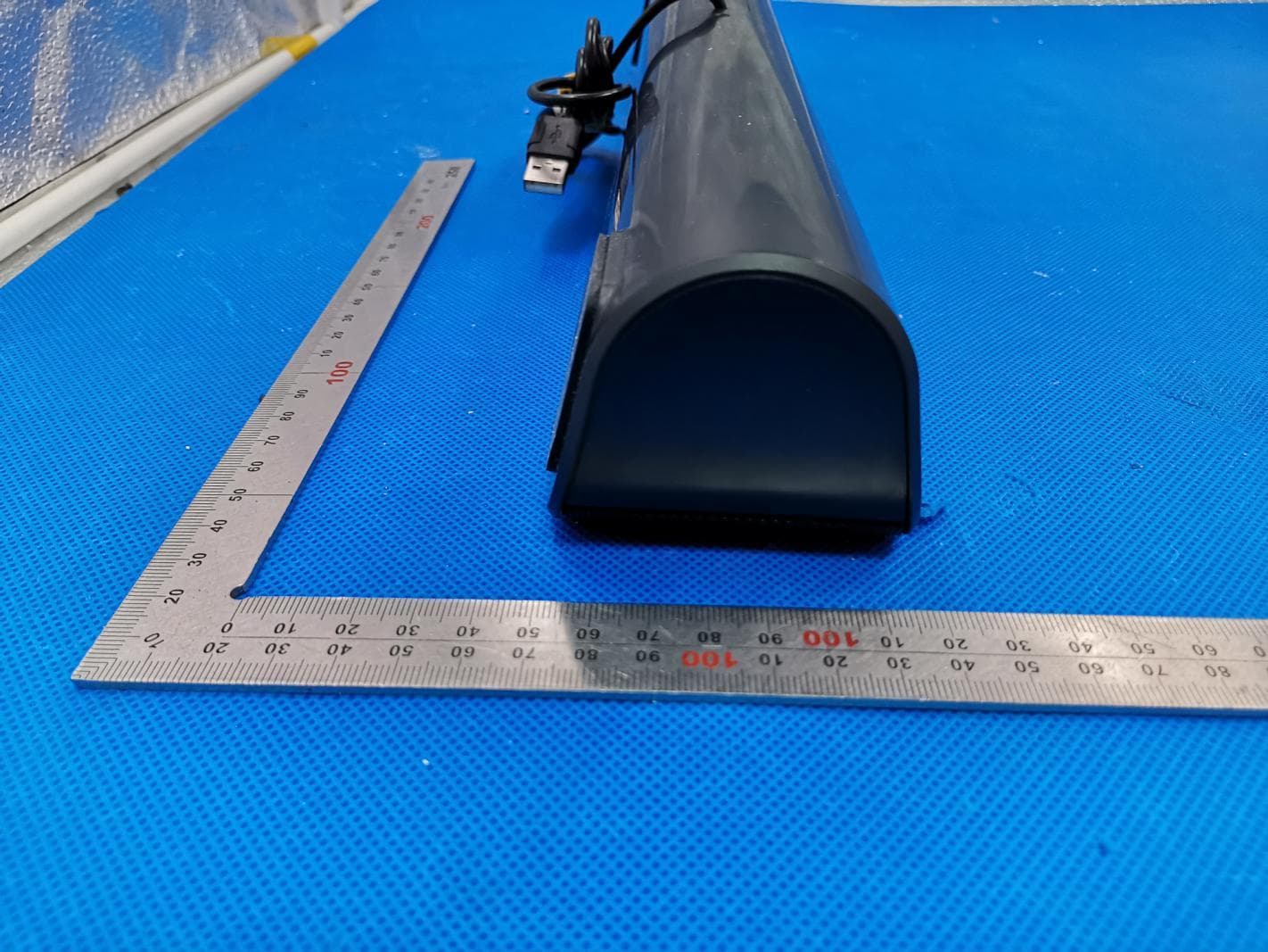
2AFDGTT-SK028
May 04, 2020PC Sound Bar
Equipment Class
DSS - Part 15 Spread Spectrum Transmitter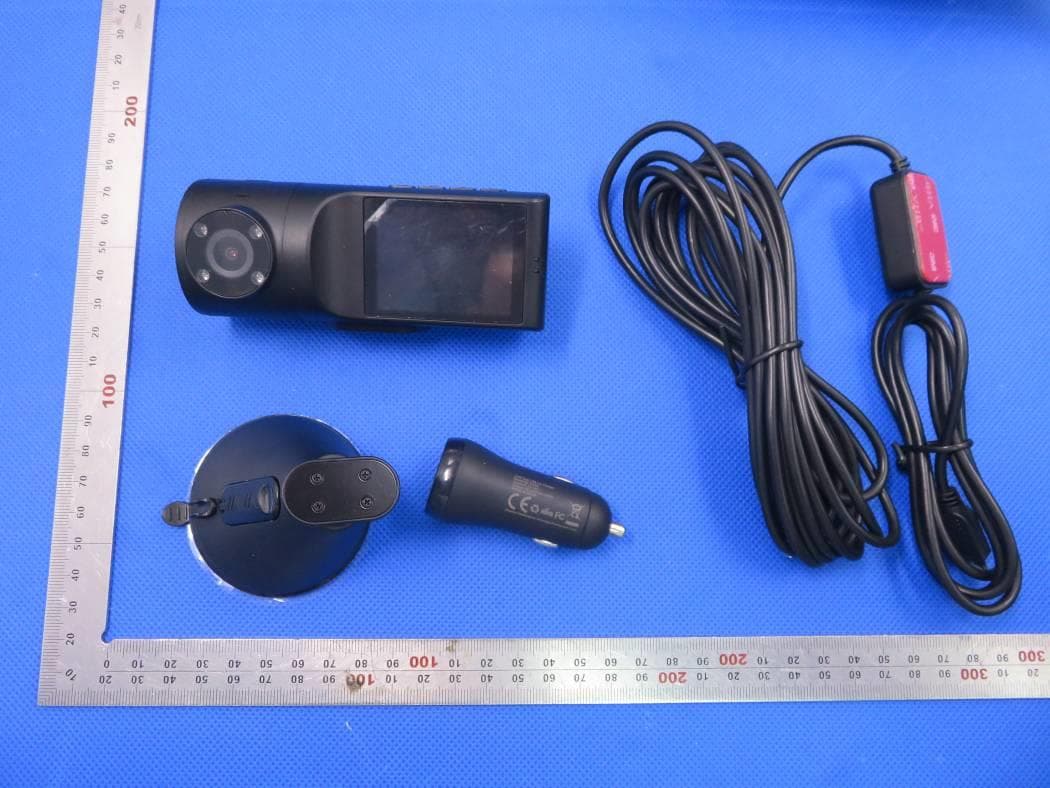
2AFDGVA-VD009
Apr 08, 2020VAVA 2K DUAL DASH CAM
Equipment Class
DTS - Digital Transmission System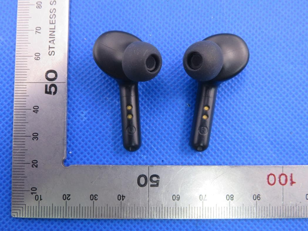
2AFDGTT-BH053V1
Jan 19, 2020TRUE WIRELESS STEREO EARBUDS
Equipment Class
DSS - Part 15 Spread Spectrum Transmitter
2AFDGBT-BH021
Jan 08, 2020TRUE WIRELESS STEREO EARBUDS
Equipment Class
DSS - Part 15 Spread Spectrum Transmitter