2AFDGTT-SK028PC Sound Bar
SUNVALLEYTEK INTERNATIONAL, INC.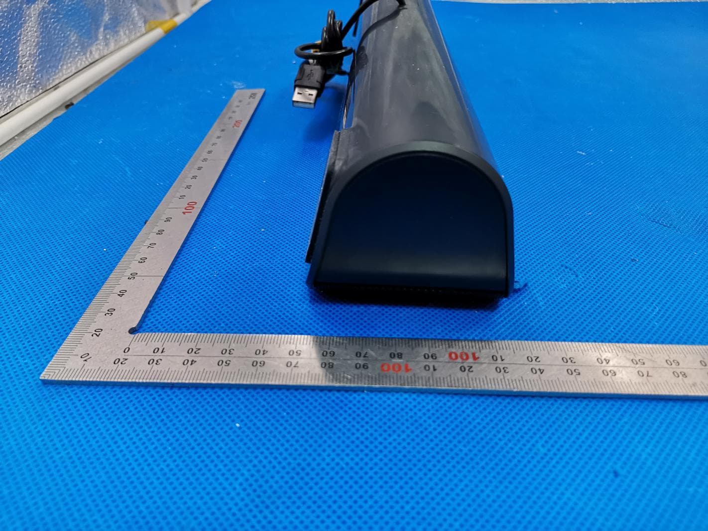
Click to zoom
Application Details
- Equipment Class
- DSS - Part 15 Spread Spectrum Transmitter
- Date of Grant
- May 04, 2020
- Application Purpose
- Original Equipment
- Date of Application
- May 04, 2020
- Equipment Note
- PC Sound Bar
- Frequency Range
- 2402.00000000 - 2480.00000000
- Country
- United States
Documents & Files
Document Text
Text extracted from the exhibit documents filed with the FCC. Open a document above to read the original.
Users Manual
IMPORTANT SAFETY INSTRUCTIONS Package Contents Product DiagramButton Control Use Your Sound Bar Cleaning and Maintenance Warranty and Service Thanks for choosing TaoTronics PC Sound Bar. Please read this User Guide thoroughly before use and retain it for future reference. WARNING To reduce the risk of fire or electric shock, do not expose this appliance to rain or moisture. Keep the sound bar away from extreme heat and humidity, and do not expose to direct sunlight. Do not place near any heat sources such as radiators, heat registers, stoves, etc. Only use this Sound Bar indoors. Never place this Sound Bar on other electrical equipment. Keep the Sound Bar clean and dry. Do not clean the product with detergent containing alcohol, ammonia, benzene or abrasives. CAUTION Do not scrape the surface with sharp objects. Do not block any ventilation openings. Unplug this device during lightning storms or when not used for long periods of time. Do not drop or knock your sound bar on hard surfaces as it may damage the interior circuits. Protect the power cord from being walked on or pinched particularly at plugs, convenience receptacles, and the point where they exit from the device. Close attention is needed when using near children. Unauthorized disassembly of any parts of this appliance is forbidden. Always ask a professional technician or authorized personnel for repair. Do not use chemicals or detergents to clean the appliance. Clean only with a dry cloth. READ AND SAVE THESE INSTRUCTIONS · 1 x TaoTronics PC Sound Bar (TT-SK028) · 1 x 3.5mm Audio Cable · 1 x User Guide · 1 x Thank You Card Function Power On Power Off Bluetooth® Mode On / Off Bluetooth® Pairing Successfully Connected Volume + Operation Connect with any USB charging adapter or active computer USB port Unplug the USB power cord Press the Volume Knob twice / / Turn the Volume Knob clockwise Voice Prompt / Beep Beep Beep Beep when highest setting is reached LED Indicator Volume Knob indicator stays solid blue / Bluetooth® indicator flashes blue and white alternately Bluetooth® indicator flashes blue every 5 seconds Function Volume - Play / Pause Answer / Hang Up Phone Call Decline an Incoming Call Bluetooth® Out of Range Operation Turn the Volume Knob anticlockwise Press the Volume Knob once Press the Volume Knob once Press and hole the Volume Knob for 1 second / Voice Prompt / / Beep when answering / / LED Indicator Bluetooth® indicator flashes blue every 5 seconds Bluetooth® indicator flashes blue and white alternately Place the Sound Bar 1.Place this unit on a level table near the place where the USB power plug can be easily reached. 2.Never place this unit in an enclosed cabinet when the sound bar is playing. Bluetooth® Connection 1. Connect the sound bar with any USB charging adapter or active computer USB port to turn on the unit. 2. Press the Volume Knob twice to turn on Bluetooth® mode. The Bluetooth® indicator will flash blue and white alternately indicating the sound bar is in pairing mode now. 3. Turn on the Bluetooth® function on your device and search for nearby devices. Find “TaoTronics TT-SK028” in the search results and tap to connect. 4. Once connected, a beep will be heard and the Bluetooth® indicator will flash blue every 5 seconds. Note: When the Bluetooth® mode is turned on, the sound bar will automatically enter pairing and re-pairing mode. If the sound bar has been connected before, it will attempt to pair with the last connected device. If not, the sound bar will enter pairing mode for pairing with other Bluetooth® device. Please make sure no other active Bluetooth® devices are within range, and that the sound bar is within 3ft / 1m away from your device. AUX Cable Connection 1.Connect the sound bar with any USB power adapter or active computer USB port to turn on the unit. 2.Plug in the 3.5mm audio cable into the AUX IN port at the back of the sound bar. 3.Connect to your AUX device via the cable. Note: Once connected to the AUX OUT port, the sound will be bypassed to the audio device connected. Make sure the music is at audile level and tune the volume through the Volume Knob. Clean the Sound Bar on a regular basis. Use dry and soft cotton cloth to wipe the unit. Keep away from sharp objects to avoid scratches. Put the unit in a dry and shady place if it is to be idle for a long time. Do not clean the product with detergent or chemicals. Do not insert anything into the product. This product is covered with TaoTronics product and labor warranty for 12 months from the date of its original purchase. If any problems occur, please contact the TaoTronics Customer Care Centre in your country via the contact information listed in this User Guide. We can only provide after sales service for products that are sold by TaoTronics or TaoTronics authorized retailers and distributors. If you have purchased your unit from a different place, please contact your seller for return and warranty issues. Model: TT-SK028 TaoTronics PC Sound Bar User Guide ASIA PACIFIC E-mail: [email protected](JP) JP Importer: SUNVALLEY JAPAN Address: 104-0032 318-6 PMO 9F NORTH AMERICA E-mail: [email protected](US) [email protected](CA) Tel: 1-888-456-8468 (Monday-Friday: 9:00 – 17:00 PST) MANUFACTURER Manufacturer: Shenzhen NearbyExpress Technology Development Co.,Ltd. Address: Floor 7, Building E, Galaxy World Phase II, Shenzhen, China MADE IN CHINA 03-13-2020 TT-SK028_V1.1_EN-JP www.taotronics.com AUX OUTAUX IN ①②③ ⑥⑤④ ① Volume Knob ② Volume Knob Indicator ③ Bluetooth® Indicator ④ AUX OUT Port ⑤ AUX IN port ⑥ USB Power Cord Back 1 x TaoTronics (TT-SK028) 1 x 3.5mm 1 x 1 x EN The Bluetooth® word mark and logos are registered trademarks owned by the Bluetooth SIG, Inc. and any use of such marks by Sunvalleytek International Inc. is under license. Other trademarks and trade names are those of their respective owners. JP NOTE: This equipment has been tested and found to comply with the limits for a Class B digital device, pu…
Text truncated - open the document above for the full version.
Cover Letter(s)
SUNVALLEYTEK INTERNATIONAL, INC. 46724 Lakeview Blvd, Fremont, CA 94538-6529 [Apr. 20, 2020] Federal Communications Commission 445 12 th Street SW Washington, DC 20554 Subject: Limited Agency Agreement SUNVALLEYTEK INTERNATIONAL, INC. FCC ID: 2AFDGTT-SK028 To Whom It May Concern: We, SUNVALLEYTEK INTERNATIONAL, INC. hereby authorized Intertek Testing Services to act as our Agent for the purpose of preparing application for FCC ID number (2AFDGTT-SK028) under all applicable parts of the FCC rules and regulations. The effective date of this limited agency agreement is (2020-04-20). The Limited Agency Agreement expires until further notice, unless sooner terminated or extended by written notice to Intertek Testing Services and the Federal Communications Commission. This is to advise that we are in full compliance with the Anti-Drug Abuse Act. The applicant is not subject to a denial of federal benefits pursuant to Section 5301 of the Anti-Drug Act of 1988, 21 U.S.C. 862, and no party to the application is subject to a denial of federal benefits pursuant to that section. If you have any questions or comments, please do not hesitate to contact me. Sincerely, [Signature] SUNVALLEYTEK INTERNATIONAL, INC. Contact person: kent peng Title: General Manager
Cover Letter(s)
SUNVALLEYTEK INTERNATIONAL, INC. 46724 Lakeview Blvd, Fremont, CA 94538-6529 Apr. 20, 2020 Federal Communication Commission Authorization and Evaluation Division FCC ID: 2AFDGTT-SK028 Re: Confidentiality Request Pursuant to Sections 0.457 and 0.459 of the Commission’s Rules, the applicant hereby requests confidential treatment of information applied this application as outlined below: 1: Block Diagram 2: Schematics 3: Operational Description The above materials contain trade secrets and proprietary information not customarily released to the public. The public disclosure of these matters might be harmful to the applicant and provide unjustified benefits to its competitors. The Applicant understands that pursuant to Rules 0.457, disclosure of this Application and all accompanying documentation will not be made before the date of the Grant for this application. Sincerely, SUNVALLEYTEK INTERNATIONAL, INC. Contact person: kent peng Title: General Manager
External Photos
External Photos Test Model: TT-SK028 ALL VIEW OF EUT TOP VIEW OF EUT BOTTOM VIEW OF EUT FRONT VIEW OF EUT BACK VIEW OF EUT LEFT VIEW OF EUT RIGHT VIEW OF EUT VIEW OF EUT(PORT)-1 VIEW OF EUT(PORT)-2
ID Label/Location Info
FCC ID Label Location 60mm*29mm
Internal Photos
Internal Photos Test Model: TT-SK028 OPEN VIEW -1 OF EUT OPEN VIEW -2 OF EUT INTERNAL VIEW-1 OF EUT INTERNAL VIEW-2 OF EUT INTERNAL VIEW-3 OF EUT INTERNAL VIEW-4 OF EUT Antenna INTERNAL VIEW-5 OF EUT INTERNAL VIEW-6 OF EUT
RF Exposure Info
RF EXPOSURE EVALUATION 1. PRODUCT INFORMATION Product Description PC Sound Bar Model Name TT-SK028 FCC ID 2AFDGTT-SK028 2. EVALUATION METHOD According to 447498 D01 General RF Exposure Guidance v05 The 1-g and 10-g SAR test exclusion thresholds for 100 MHz to 6 GHz at test separation distances ≤ 50 mm are determined by: [(max. power of channel, including tune-up tolerance, mW)/(min. test separation distance, mm)] ·[√f(GHz)] ≤ 3.0 for 1-g SAR and ≤ 7.5 for 10-g extremity SAR. Where f(GHz) is the RF channel transmit frequency in GHz Power and distance are rounded to the nearest mW and mm before calculation 3. CALCULATION P t =3.328dBm=2.15mW The value of the Maximum output power P t is referred to the test report of the CFR47 §15.247. The result for RF exposure evaluation SAR=(2.15mW /5mm) .[√2.48(GHz)]= 0.68<3.0 for 1-g SAR and ≤ 7.5 for 10-g extremity SAR. 4. CONCLUSION The SAR evaluation is not required.
Test Report
Page 1 of 70 FCC Test Report Report No.: AGC00210200318FE03 FCC ID : 2AFDGTT-SK028 APPLICATION PURPOSE : Original Equipment PRODUCT DESIGNATION : PC Sound Bar BRAND NAME : TAOTRONICS MODEL NAME : TT-SK028 APPLICANT : SUNVALLEYTEK INTERNATIONAL, INC. DATE OF ISSUE : Apr. 19, 2020 STANDARD(S) : FCC Part 15.247 REPORT VERSION : V1.0 Attestation of Global Compliance (Shenzhen) Co., Ltd CAUTION: This report shall not be reproduced except in full without the written permission of the test laboratory and shall not be quoted out of context. Report No.: AGC00210200318FE03 Page 2 of 70 REPORT REVISE RECORD Report Version Revise Time Issued Date Valid Version Notes V1.0 / Apr. 19, 2020 Valid Initial Release Report No.: AGC00210200318FE03 Page 3 of 70 TABLE OF CONTENTS 1. VERIFICATION OF CONFORMITY ..............................................................................................................5 2. GENERAL INFORMATION ..........................................................................................................................6 2.1. PRODUCT DESCRIPTION ....................................................................................................................6 2.2. TABLE OF CARRIER FREQUENCYS ....................................................................................................6 2.3. RECEIVER INPUT BANDWIDTH ...........................................................................................................7 2.4. EXAMPLE OF A HOPPING SEQUENCY IN DATA MODE .......................................................................7 2.5. EQUALLY AVERAGE USE OF FREQUENCIES AND BEHAVIOUR ........................................................7 2.6. RELATED SUBMITTAL(S) / GRANT (S) .................................................................................................8 2.7. TEST METHODOLOGY .........................................................................................................................8 2.8. SPECIAL ACCESSORIES .....................................................................................................................8 2.9. EQUIPMENT MODIFICATIONS .............................................................................................................8 3. MEASUREMENT UNCERTAINTY ...............................................................................................................9 4. DESCRIPTION OF TEST MODES ............................................................................................................. 10 5. SYSTEM TEST CONFIGURATION ............................................................................................................ 11 5.1. CONFIGURATION OF EUT SYSTEM .................................................................................................. 11 5.2 EQUIPMENT USED IN TESTED SYSTEM ........................................................................................... 11 5.3. SUMMARY OF TEST RESULTS .......................................................................................................... 11 6. TEST FACILITY ......................................................................................................................................... 12 7. PEAK OUTPUT POWER ........................................................................................................................... 13 7.1. MEASUREMENT PROCEDURE.......................................................................................................... 13 7.2. TEST SET-UP (BLOCK DIAGRAM OF CONFIGURATION) .................................................................. 13 7.3. LIMITS AND MEASUREMENT RESULT .............................................................................................. 14 8. 20DB BANDWIDTH ................................................................................................................................... 20 8.1. MEASUREMENT PROCEDURE.......................................................................................................... 20 8.2. TEST SET-UP (BLOCK DIAGRAM OF CONFIGURATION) .................................................................. 20 8.3. LIMITS AND MEASUREMENT RESULTS ............................................................................................ 20 9. CONDUCTED SPURIOUS EMISSION ....................................................................................................... 27 9.1. MEASUREMENT PROCEDURE.......................................................................................................... 27 9.2. TEST SET-UP (BLOCK DIAGRAM OF CONFIGURATION) .................................................................. 27 9.3. MEASUREMENT EQUIPMENT USED ................................................................................................. 27 Report No.: AGC00210200318FE03 Page 4 of 70 9.4. LIMITS AND MEASUREMENT RESULT .............................................................................................. 27 10. RADIATED EMISSION ............................................................................................................................. 37 10.1. MEASUREMENT PROCEDURE ........................................................................................................ 37 10.2. TEST SETUP ..................................................................................................................................... 39 10.3. LIMITS AND MEASUREMENT RESULT ............................................................................................ 40 10.4. TEST RESULT ................................................................................................................................... 40 11. NUMBER OF HOPPING FREQUENCY .................................................................................................... 50 11.1. MEASUREMENT PROCEDURE .....................................................................…
Text truncated - open the document above for the full version.
Test Report
Report No.: AGC00210200318FE03 Page 36 of 70 8-DPSK MODULATION IN HIGH CHANNEL Hopping off Hopping on Report No.: AGC00210200318FE03 Page 37 of 70 10. RADIATED EMISSION 10.1. MEASUREMENT PROCEDURE 1. The EUT was placed on the top of the turntable 0.8 or 1.5 meter above ground. The phase center of the receiving antenna mounted on the top of a height-variable antenna tower was placed 3 meters far away from the turntable. 2. Power on the EUT and all the supporting units. The turntable was rotated by 360 degrees to determine the position of the highest radiation. 3. The height of the broadband receiving antenna was varied between one meter and four meters above ground to find the maximum emissions field strength of both horizontal and vertical polarization. 4. For each suspected emissions, the antenna tower was scan (from 1 M to 4 M) and then the turntable was rotated (from 0 degree to 360 degrees) to find the maximum reading. 5. Set the test-receiver system to Peak or CISPR quasi-peak Detect Function with specified bandwidth under Maximum Hold Mode. 6. For emissions above 1GHz, use 1MHz RBW and 3MHz VBW for peak reading. Place the measurement antenna away from each area of the EUT determined to be a source of emissions at the specified measurement distance, while keeping the measurement antenna aimed at the source of emissions at each frequency of significant emissions, with polarization oriented for maximum response. The measurement antenna may have to be higher or lower than the EUT, depending on the radiation pattern of the emission and staying aimed at the emission source for receiving the maximum signal. The final measurement antenna elevation shall be that which maximizes the emissions. The measurement antenna elevation for maximum emissions shall be restricted to a range of heights of from 1 m to 4 m above the ground or reference ground plane. 7. When the radiated emissions limits are expressed in terms of the average value of the emissions, and pulsed operation is employed, the measurement field strength shall be determined by averaging over one complete pulse train, including blanking intervals, as long as the pulse train does not exceed 0.1 seconds. As an alternative (provided the transmitter operates for longer than 0.1 seconds) or in cases where the pulse train exceeds 0.1 seconds, the measured field strength shall be determined from the average absolute voltage during a 0.1 second interval during which the field strength is at its maximum values. 8.If the emissions level of the EUT in peak mode was 3 dB lower than the average limit specified, then testing will be stopped and peak values of EUT will be reported, otherwise, the emissions which do not have 3 dB margin will be repeated one by one using the quasi-peak method for below 1GHz. 9. For testing above 1GHz, the emissions level of the EUT in peak mode was lower than average limit (that means the emissions level in peak mode also complies with the limit in average mode), then testing will be stopped and peak values of EUT will be reported, otherwise, the emissions will be measured in average mode again and reported. 10. In case the emission is lower than 30MHz, loop antenna has to be used for measurement and the recorded data should be QP measured by receiver. High - Low scan is not required in this case. Report No.: AGC00210200318FE03 Page 38 of 70 The following table is the setting of spectrum analyzer and receiver. Spectrum Parameter Setting Start ~Stop Frequency 9KHz~150KHz/RB 200Hz for QP Start ~Stop Frequency 150KHz~30MHz/RB 9KHz for QP Start ~Stop Frequency 30MHz~1000MHz/RB 120KHz for QP Start ~Stop Frequency 1GHz~26.5GHz 1MHz/3MHz for Peak, 1MHz/3MHz for Average Receiver Parameter Setting Start ~Stop Frequency 9KHz~150KHz/RB 200Hz for QP Start ~Stop Frequency 150KHz~30MHz/RB 9KHz for QP Start ~Stop Frequency 30MHz~1000MHz/RB 120KHz for QP Report No.: AGC00210200318FE03 Page 39 of 70 10.2. TEST SETUP Radiated Emission Test-Setup Frequency Below 30MHz RADIATED EMISSION TEST SETUP 30MHz-1000MHz RADIATED EMISSION TEST SETUP ABOVE 1000MHz Report No.: AGC00210200318FE03 Page 40 of 70 10.3. LIMITS AND MEASUREMENT RESULT 15.209 Limit in the below table has to be followed Frequencies (MHz) Field Strength (micorvolts/meter) Measurement Distance (meters) 0.009~0.490 2400/F(KHz) 300 0.490~1.705 24000/F(KHz) 30 1.705~30.0 30 30 30~88 100 3 88~216 150 3 216~960 200 3 Above 960 500 3 Note: All modes were tested For restricted band radiated emission, the test records reported below are the worst result compared to other modes. 10.4. TEST RESULT RADIATED EMISSION BELOW 30MHZ No emission found between lowest internal used/generated frequencies to 30MHz. Report No.: AGC00210200318FE03 Page 41 of 70 RADIATED EMISSION BELOW 1GHZ EUT PC Sound Bar Model Name TT-SK028 Temperature 25°C Relative Humidity 55.4% Pressure 960hPa Test Voltage Normal Voltage Test Mode Mode 4 Antenna Horizontal RESULT: PASS Report No.: AGC00210200318FE03 Page 42 of 70 EUT PC Sound Bar Model Name TT-SK028 Temperature 25°C Relative Humidity 55.4% Pressure 960hPa Test Voltage Normal Voltage Test Mode Mode 4 Antenna Vertical RESULT: PASS Note: 1. Factor=Antenna Factor + Cable loss, Margin=Measurement-Limit. 2. All test modes had been pre-tested. The mode 4 is the worst case and recorded in the report. Report No.: AGC00210200318FE03 Page 43 of 70 RADIATED EMISSION ABOVE 1GHZ EUT PC Sound Bar Model Name TT-SK028 Temperature 25°C Relative Humidity 55.4% Pressure 960hPa Test Voltage Normal Voltage Test Mode Mode 1 Antenna Horizontal FrequencyMeter ReadingFactor Emission LevelLimitsMargin (MHz)(dBμV) (dB)(dBμV/m)(dBμV/m)(dB) Value Type 4804.022 4804.022 7206.033 7206.033 51.450.08 43.750.08 44.832.21 37.142.21 51.5374-22.47 peak 43.8354-10.17 AVG 47.0474-26.96 peak 39.3554-14.65 AVG Remark: Factor = Antenna Factor + Cable Loss – Pre-amplifier. EUT PC Sound Bar Model Name TT-SK028 Temperature 25°C Relative Humidity 55.4% Pressure 960hPa Test Voltage Normal Voltage Test Mode …
Text truncated - open the document above for the full version.
Test Setup Photos
Test Setup Photos Test Model: TT-SK028 RADIATED EMISSION TEST SETUP BELOW 1GHZ RADIATED EMISSION TEST SETUP ABOVE 1GHZ CONDUCTED EMISSION TEST SETUP
Contact Information
Applicant
kent peng
Technical Contact
Attestation of Global Compliance (Shenzhen) Co., LYimi Zhao
[email protected]86-755-29081977
2F.,No.2 Building, Huafeng No.1 Technical Industri · Shenzhen · China
Test Firm
Attestation of Global Compliance (Shenzhen) Co., LDoris Li
[email protected]+86-755-25234088
Technical Specifications
| # | Rule Parts | Frequency Range | Power Output |
|---|---|---|---|
| 1 | 15C | 2.40 GHz - 2.48 GHz | 2.15 mW |
Other Applications from SUNVALLEYTEK INTERNATIONAL, INC.
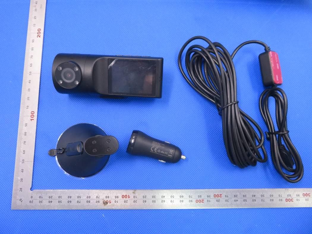
2AFDGVA-VD009
Apr 08, 2020VAVA 2K DUAL DASH CAM
Equipment Class
DTS - Digital Transmission System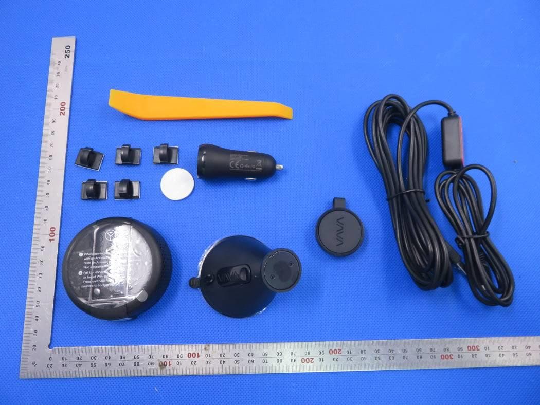
2AFDGVA-VD004V1
Apr 07, 2020DASH CAM
Equipment Class
DTS - Digital Transmission System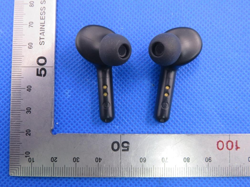
2AFDGTT-BH053V1
Jan 19, 2020TRUE WIRELESS STEREO EARBUDS
Equipment Class
DSS - Part 15 Spread Spectrum Transmitter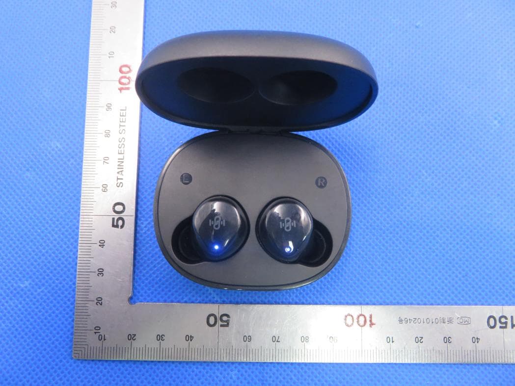
2AFDGBT-BH021
Jan 08, 2020TRUE WIRELESS STEREO EARBUDS
Equipment Class
DSS - Part 15 Spread Spectrum Transmitter