2AP35BT0554FF0810LED SHOP LIGHT
INTERNATIONAL DEVELOPMENT COMPANY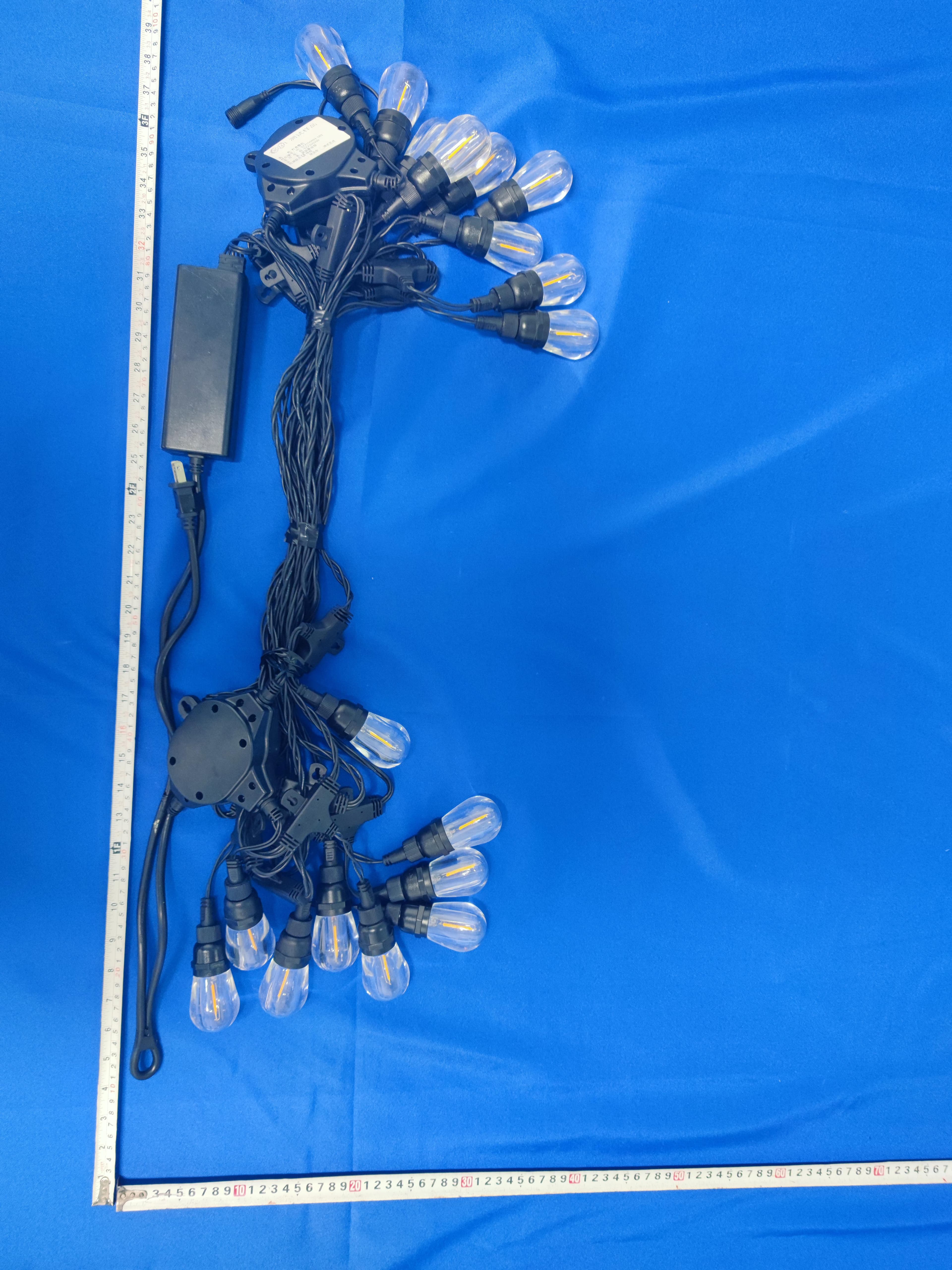
Click to zoom
Application Details
- Equipment Class
- DSS - Part 15 Spread Spectrum Transmitter
- Date of Grant
- Jul 11, 2021
- Application Purpose
- Original Equipment
- Date of Application
- Jul 11, 2021
- Equipment Note
- LED SHOP LIGHT
- Frequency Range
- 2402.00000000 - 2480.00000000
- Country
- United States
Documents & Files
Document Text
Text extracted from the exhibit documents filed with the FCC. Open a document above to read the original.
Users Manual
17” 11” FoldFold FoldFold EN | 4 Model: BT0554FF0810 Use and Care Guide Read and Save These Instructions Before Use EN LED Indoor/Outdoor String Light with Bluetooth Speakers NOTE: The Bluetooth brand elements may not be used in a fashion or manner that could impair or otherwise damage the goodwill associated with the Bluetooth brand or the Fellow Adopters (International Development Company). The Bluetooth brand elements shall therefore not be used in connection with products and services that do not enable any Bluetooth wireless functionality or in connection with unlawful, obscene, pornographic, excessively violent, hazardous,or otherwise poor-taste activities. PROBLEM Light will not come on.A. Light not plugged into outlet. B. Outlet not powered. C. Bulb(s) not lighting A. Plug power cord into outlet. B. Check to make sure breaker is on and test outlet with another working electrical device to make sure it is receiving power. NOTE: Unplug power cord first. C1. Check to see if screw cap is tight. If loose, hand tighten. C2. If screw cap is tight: Unscrew cap, remove bulb and re-insert bulb. Hand tighten. If bulb is still not lighting, contact customer service. POSSIBLE CAUSESOLUTION TROUBLE SHOOTING Bluetooth audio does not work. Audio can be heard out of first string light only in linked chain. A. Check to make sure aux cables are properly installed on all linked lights. A. Bluetooth not active or not close enough to device. B. Bluetooth may be paired to wrong device. C. Device volume may be low or muted. A. Ensure your device's Bluetooth is turned on, in range and discoverable. B. Make sure you are selecting the correct device to pair to. C. Makes sure your audio level is set appropriately. A. Aux Cords are not connected on linked lights. International Development Company 899 Henrietta Creek Rd. Roanoke, Roanoke, TX 76262 USA Toll-free: 1-877-723-0723 Made in China © 2021 IDC, all rights reserved. The Honeywell Trademark is used under license from Honeywell International Inc. Honeywell International Inc. makes no representations or warranties with respect to this product. This product is manufactured for International Development Company. HOW TO OPERATE BLUETOOTH SPEAKER: Bluetooth Speakers will enter pairing mode when you turn on the light. Activate bluetooth on your device and find device named BT0554FF0020. Press to pair. The Bluetooth Speakers will turn off when the light is turned off. 1. 2. 65.6ft (20m) For most reliable operation the distance between Bluetooth device and the string light should be less than 65.6ft(20m). NOTE: Bluetooth performance can also be affected by Bluetooth device used and your individual environment (i.e. clear line of sight between device and string light normally provides better performance than multiple walls between device and string light). Bluetooth Speakers Aux Out Aux In IMPORTANT SAFETY INSTRUCTIONS WARNING: Changes or modifications to this unit not expressly approved by the party responsible for compliance could void the user authority to operate the equipment. ********************************************************************************************** FCC WARNING: NOTES:This equipment has been tested and found to comply with the limits for a Class B digital device, pursuant to Part 15 of the FCC Rules. These limits are designed to provide reasonable protection against harmful interference in a residential installation. This equipment generates, uses and can radiate radio frequency energy and, if not installed and used in accordance with the instructions, may cause harmful interference to radio communications. However, there is no guarantee that interference will not occur in a particular installation. If this equipment does cause harmful interference to radio or television reception, which can be determined by turning the equipment off and on, the user is encouraged to try to correct the interference by one or more of the following measures: • Reorient or relocate the receiving antenna. • Increase the separation between the equipment and receiver. • Connect the equipment into an outlet on a circuit different from that to which the receiver is connected. • Consult the dealer or an experienced radio/TV technician for help. This device complies with Part 15 of the FCC Rules. Operation is subject to the following two conditions: (1) this device may not cause harmful interference, and (2) this device must accept any interference received, including interference that may cause undesired operation. Note: This portable luminaire has a polarized plug (one blade is wider than the other) as a feature to reduce the risk of electric shock. This plug will fit in a polarized outlet only one way. If the plug does not fit fully in the outlet, reverse the plug. If it still does not fit, contact a qualified electrician. Never use with an extension cord unless plug can be fully inserted. Do not alter the plug. INSTALLATION IMPORTANT SAFETY INSTRUCTIONS IMPORTANT: Read all safety precautions and installation instructions carefully before installing or servicing this fixture. Failure to comply with these instructions could result in a potentially fatal electric shock, fire, and/or property damage. In order to ensure proper installation, please follow each step below. WARNING • ATTENTION RISK OF ELECTRIC SHOCK • RISQUE DE CHOC ÉLECTRIQUE • RECEPTACLE OUTLETS USED FOR POWERING STRING LIGHTS SHALL COMPLY WITH ALL NATIONAL AND LOCAL ELECTRICAL CODES. • CONSULT LOCAL ELECTRICIAN IF UNSURE OF COMPLIANCE REQUIREMENTS. • DO NOT SUBMERSE. • DO NOT USE AROUND AQUARIUMS. • STRING LIGHTS ARE A WET LOCATION PRODUCT AND HAVE NO REPLACEABLE OR SERVICEABLE PARTS. • DO NOT USE WITH EXTENSION CORD NEAR WATER OR WHERE WATER MAY ACCUMULATE. • KEEP LAMPS AT LEAST 16 FEET FROM POOLS AND SPAS. • KEEP PLUGS AND RECEPTACLES DRY. • AVOID DAMAGE TO THE CORDS AND LAMP ASSEMBLIES DURING INSTALLATION. PERIODICALLY INSPECT THE STRING LIGHTS FOR PHYSICAL DAMAGE OR OTHER DAMAGE CAUSED BY OUTDO…
Text truncated - open the document above for the full version.
Cover Letter(s)
Date: 5 July 2021 INTERNATIONAL DEVELOPMENT COMPANY To: Federal Communications Commission, Authorization & Evaluation Division, 7435 Oakland Mills Road, Columbia, MD 21046 To Whom It May Concern: The INTERNATIONAL DEVELOPMENT COMPANY, the undersigned, hereby authorizes Mr. Wu Xuewen from Shenzhen BALUN Technology Co., Ltd., to act on the behalf of the INTERNATIONAL DEVELOPMENT COMPANY solely in matters relating to the application for an FCC equipment authorization for FCC ID: 2AP35BT0554FF0810 including the signing of documents in connection with this Application. Necessary acts carried out by Shenzhen BALUN Technology Co., Ltd. in connection with the Application shall have the same effect as acts of the INTERNATIONAL DEVELOPMENT COMPANY. The INTERNATIONAL DEVELOPMENT COMPANY also hereby certify that no party to this application is subject to a denial of benefits, including FCC benefits, pursuant to Section 5301 of the Anti-Drug Abuse Act of 1988, 21 U.S.C. Section 862. Yours Sincerely, _______ zhiquan li
Cover Letter(s)
Date: 5 July 2021 INTERNATIONAL DEVELOPMENT COMPANY To: Federal Communications Commission, Authorization & Evaluation Division, 7435 Oakland Mills Road, Columbia, MD 21046 Re: INTERNATIONAL DEVELOPMENT COMPANY FCC ID: 2AP35BT0554FF0810 FCC Certification Confidentiality Request Gentlemen: This letter is to comply with 47 CFR 0.457 and 0.459 pertaining to confidentiality material. INTERNATIONAL DEVELOPMENT COMPANY requests that the following documents regarding this submission for FCC ID: 2AP35BT0554FF0810 be kept confidential: Exhibit Type File Name Block Diagram Block Diagram.pdf Schematics Schematics.pdf Operational Description Operational Description.pdf And below exhibit kept short-term confidential (180 days): External photos External photos.pdf Test setup photos test photo.pdf Internal photos Internal photos.pdf User manual User manual.pdf Those documents contain detailed system and equipment description and related information about the product which INTERNATIONAL DEVELOPMENT COMPANY considers to be confidential proprietary, a custom design and, otherwise, not releasable to the general public. Since this design is a basis form which future technological products will evolve, INTERNATIONAL DEVELOPMENT COMPANY considers this information would be of benefit to its competitors, and that the disclosure of the information in these documents would give competitors an unfair advantage in the market. Yours Sincerely, zhiquan li
External Photos
AnnexNo.:BL-SZ2160299-AW 1 / 1 ANNEXCEUTEXTERNALPHOTOS FRONTVIEWOFEUT REARVIEWOFEUT
ID Label/Location Info
- i|-l
Internal Photos
Annex No.: BL-SZ2160299-AI 1 / 9 ANNEX D EUT INTERNAL PHOTOS EUT UNCOVER VIEW EUT UNCOVER VIEW Annex No.: BL-SZ2160299-AI 2 / 9 MAIN BOARD TOP VIEW MAIN BOARD BOTTOM VIEW Annex No.: BL-SZ2160299-AI 3 / 9 MAIN BOARD TOP VIEW MAIN BOARD BOTOOM VIEW PCB Antenna Annex No.: BL-SZ2160299-AI 4 / 9 MAIN BOARD TOP VIEW MAIN BOARD BOTOOM VIEW Annex No.: BL-SZ2160299-AI 5 / 9 EUT UNCOVER VIEW EUT UNCOVER VIEW Annex No.: BL-SZ2160299-AI 6 / 9 MAIN BOARD TOP VIEW MAIN BOARD BOTTOM VIEW Annex No.: BL-SZ2160299-AI 7 / 9 SPEAKER TOP VIEW SPEAKER BOTTOM VIEW Annex No.: BL-SZ2160299-AI 8 / 9 EUT UNCOVER VIEW EUT UNCOVER VIEW Annex No.: BL-SZ2160299-AI 9 / 9 EUT UNCOVER VIEW EUT UNCOVER VIEW
RF Exposure Info
RF Exposure Evaluation for FCC ID: 2AP35BT0554FF0810 Refer user manual this device is a LED String Light, and this device was designed used in portable devices that the minimum distance between human’s body is 5mm. Based on the 47CFR 2.1093, this device belongs to portable device. The definition of the category as following: Portable Derives: CFR Title 47 §2.1093(b) (b) For purposes of this section, a portable device is defined as a transmitting device designed to be used so that the radiating structure(s) of the device is/are within 20 centimeters of the body of the user. FCC KDB 447498 D01 General RF Exposure Guidance v06 Limit Unless specifically required by the published RF exposure KDB procedures, standalone 1-g head or body and 10-g extremity SAR evaluation for general population exposure conditions, by measurement or numerical simulation, is not required when the corresponding SAR Test Exclusion Threshold condition, listed below, is satisfied. These test exclusion conditions are based on source-based time-averaged maximum conducted output power of the RF channel requiring evaluation, adjusted for tune-up tolerance, and the minimum test separation distance required for the exposure conditions. The minimum test separation distance is determined by the smallest distance from the antenna and radiating structures or outer surface of the device, according to the host form factor, exposure conditions and platform requirements, to any part of the body or extremity of a user or bystander. The 1-g and 10-g SAR test exclusion thresholds for 100 MHz to 6 GHz at test separation distances ≤ 50 mm are determined by: [(max. power of channel, including tune-up tolerance, mW) / (min. test separation distance, mm)] · [√f(GHz) ] ≤ 3.0 for 1-g SAR and ≤ 7.5 for 10-g extremity SAR Where • f (GHz) is the RF channel transmit frequency in GHz • Power and distance are rounded to the nearest mW and mm before calculation • The result is rounded to one decimal place for comparison The test exclusions are applicable only when the minimum test separation distance is ≤ 50 mm and for transmission frequencies between 100 MHz and 6 GHz. When the minimum test separation distance is < 5 mm, a distance of 5 mm is applied to determine SAR test exclusion. Test data Bluetooth Mode GFSK π/4-DQPSK Low Channel Middle Channel High Channel Low Channel Middle Channel High Channel Peak Power (dBm) -0.26 0.54 1.04 0.52 1.30 1.76 Note: This report listed the worst case peak power value, please refer to RF test report for more details. Turn-up power Mode Power Range (dBm) Bluetooth (-1.00)-2.00 RF Exposure Evaluation Result Mode Tune-up limit power (dBm) Distance (mm) Calculation Frequency (MHz) Calculation Results Threshold Value Verdict Bluetooth 2.00 5 2480 0.50 3.0 Compliance --END OF REPORT--
Test Report
Report No.: BL-SZ2160299-601 2 / 70 Revision History Version Issue Date Revisions Content Rev. 01 Jul. 05, 2021 Initial Issue Rev. 02 Jul. 06, 2021 Updated the Brand Name TABLE OF CONTENTS 1 ADMINISTRATIVE DATA (GENERAL INFORMATION) .......................................................................... 5 1.1 Identification of the Testing Laboratory ....................................................................................... 5 1.2 Identification of the Responsible Testing Location ...................................................................... 5 1.3 Laboratory Condition ................................................................................................................... 5 1.4 Announce .................................................................................................................................... 5 2 PRODUCT INFORMATION ...................................................................................................................... 6 2.1 Applicant Information ................................................................................................................... 6 2.2 Manufacturer Information ............................................................................................................ 6 2.3 Factory Information ..................................................................................................................... 6 2.4 General Description for Equipment under Test (EUT) ................................................................ 6 2.5 Technical Information .................................................................................................................. 7 2.6 Additional Instructions ................................................................................................................. 8 3 SUMMARY OF TEST RESULTS .............................................................................................................. 9 3.1 Test Standards ............................................................................................................................ 9 3.2 Verdict ......................................................................................................................................... 9 4 GENERAL TEST CONFIGURATIONS ................................................................................................... 10 4.1 Test Environments .................................................................................................................... 10 4.2 Test Equipment List ................................................................................................................... 10 4.3 Measurement Uncertainty ......................................................................................................... 10 4.4 Description of Test Setup .......................................................................................................... 11 4.4.1 For Antenna Port Test ............................................................................................................... 11 4.4.2 For AC Power Supply Port Test ................................................................................................ 11 4.4.3 For Radiated Test (Below 30 MHz) ........................................................................................... 12 4.4.4 For Radiated Test (30 MHz-1 GHz) .......................................................................................... 12 4.4.5 For Radiated Test (Above 1 GHz) ............................................................................................. 13 4.5 Measurement Results Explanation Example ............................................................................. 14 4.5.1 For conducted test items: .......................................................................................................... 14 Report No.: BL-SZ2160299-601 3 / 70 5 TEST ITEMS ........................................................................................................................................... 15 5.1 Antenna Requirements .............................................................................................................. 15 5.1.1 Relevant Standards ................................................................................................................... 15 5.1.2 Antenna Anti-Replacement Construction .................................................................................. 15 5.1.3 Antenna Gain ............................................................................................................................ 15 5.2 Frequency Hopping Systems .................................................................................................... 16 5.2.1 Relevant Standards ................................................................................................................... 16 5.2.2 Description of the systems ........................................................................................................ 16 5.3 Number of Hopping Frequencies .............................................................................................. 18 5.3.1 Limit ........................................................................................................................................... 18 5.3.2 Test Setup ................................................................................................................................. 18 5.3.3 Test Procedure .......................................................................................................................... 18 5.3.4 Test Result ................................................................................................................................ 18 5.4 Peak Output Power ................................................................................................................... 19 5.4.1 Test Limit .............…
Text truncated - open the document above for the full version.
Test Setup Photos
Annex No.: BL-SZ2160299-AR 1 / 4 TEST SETUP PHOTOS 1 Radiated Test Photo Below 30MHz 30MHz-1GHz Annex No.: BL-SZ2160299-AR 2 / 4 Close-up Above 1GHz Annex No.: BL-SZ2160299-AR 3 / 4 Close-up 2 Conducted Test Photo Conducted Test-BT3.0 Annex No.: BL-SZ2160299-AR 4 / 4 3 Conducted Emissions Test Photo 1 Test Photo 2
Contact Information
Applicant
zhiquan li(Manager)
Test Firm
Shenzhen BALUN Technology Co., Ltd.Hanson Lin
[email protected]86-755-66833830
Technical Specifications
| # | Rule Parts | Frequency Range | Power Output |
|---|---|---|---|
| 1 | 15C | 2.40 GHz - 2.48 GHz | 1.50 mW |
Other Applications from INTERNATIONAL DEVELOPMENT COMPANY

2AP35-SR07PM04H41
Jan 04, 2023Solar LED Light
Equipment Class
DXX - Part 15 Low Power Communication Device Transmitter
2AP35-LV30RM01A
Dec 28, 2022Remote Controller
Equipment Class
DTS - Digital Transmission System
2AP35-SR32SL02H-08
Dec 07, 2022Solar LED Light
Equipment Class
DXX - Part 15 Low Power Communication Device Transmitter
2AP35-SR58FA01H-08
Dec 07, 2022Solar LED Light
Equipment Class
DXX - Part 15 Low Power Communication Device Transmitter
2AP35-D303353
Nov 06, 2022LED Garage Light
Equipment Class
DSS - Part 15 Spread Spectrum Transmitter