2AQ7B-IPC159Security Camera
Shenzhen Interthings Technology Co., Ltd.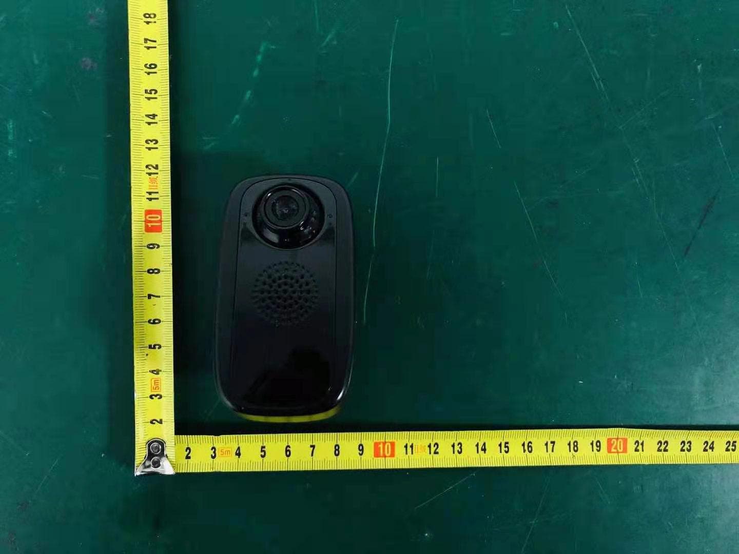
Click to zoom
Application Details
- Equipment Class
- DTS - Digital Transmission System
- Date of Grant
- Jan 07, 2021
- Application Purpose
- Original Equipment
- Date of Application
- Jan 05, 2021
- Equipment Note
- Security Camera
- Frequency Range
- 2422.00000000 - 2452.00000000
- Country
- China
Documents & Files
Document Text
Text extracted from the exhibit documents filed with the FCC. Open a document above to read the original.
Users Manual
1 Plug-in Wi-Fi Camera Instruction Manual 2 Safety Precautions 1. The working temperature of the product is -10°C~50°C. 2. Please contact the seller for assistance if there is any problem with the product and do not try to disassemble or repair the product without authority. 3. It is normal that the product body temperature goes up when the product is working. 4. Please do not short-circuit the product. Product Description This product is a Wi-Fi plug-in camera. It has a variety of functions such as two-way audio, emergency button, color night vision, video communication, voice prompts, remote monitoring, photo and video taking, motion detection, message push...etc. Users may supply power to the camera by plug it into the power outlet. Introduction of the Product 3 MicroSD Card Installation The camera supports microSD cards capacity from 8GB to 32GB (class 6 or faster). Please insert the microSD card into the microSD card slot according to the following illustration. One-touch Call Out Button When the person at the camera end wishes to reach the app owner, press the button to send out the request for two-way audio. When the app owner accepts the request, the camera will be activated. This feature can be used for some emergency cases. Color Night Vision This camera is equipped with a special image sensor that brings color night vision except the following circumstances. 1. When the camera is in a complete dark environment, no night vision image will be seen. 2. When the camera is in very low light environments, it will switch to black and white night vision to avoid excess image noises. Camera Angle Adjustment The camera is equipped with a manually angle adjustable lens. Please set the lens at your preferred angle. No. Name Functions & Remarks 1 MicroSD Card slot 8GB~32GB (class 6 or faster) 2 Reset Hole For resetting the camera (Please gently pin into it for 3~5 seconds). 3 Power Plugs To turn on the camera, insert the power plugs to a power outlet. To turn off the camera, remove the camera from the power outlet. (US version plugs: AC 100V~240V) 4 Camera Angle adjustable 5 Built-in Speaker 6 Built-in Microphone 7 On-touch Call Out Button Please see the details in “On-touch Call Out Button” 8 Red LED working indicator Flashing: Waiting for Wi-Fi pairing and connection 9 Blue LED working indicator (a) Flashing: During Wi-Fi pairing and connection. (b) Solid lit: Connected to Wi-Fi successfully. 4 How To Reset The Camera 1. Make sure the camera is powered on. 2. Make sure the blue LED indicator is being solid lit. 3. Insert the provided reset pin gently into the reset hole for 3~5 seconds. 4. The reset is done successfully after the voice prompt of “reset success” is heard and the red LED is flashing for Wi-Fi pairing. Obtaining the App This plug-in IP camera supports external devices such as mobile phones that the O/S versions are Android 5.0 or later, and iOS 10.0 or later. l The App can be obtained by the following two ways. 1. Download the App from Google Play/Android Market or App Store. (a) Android devices: Please search “TuyaSmart” from Google Play/Android Market. (b) iOS devices: Please search “TuyaSmart” from App Store. 2. Use the external device to scan the following QR code, available for both Android and iOS system Note: Scan the QR code, it will turn to default browser (e.g. Safari), then open it to the Google Play or App Store to download the App. 5 Register a Tuya account d) Users will receive a 6-digit code from text or email. e) Set a password including alphabets and numbers. a) Open the app b) ‘Register’ c) Users could use mobile number or email address to create an account. f) Create family to add devices. 6 Wi-Fi Connection l Preparation 1. Plug in the device, the LED working indicator will start flashing red light which indicates that the device is ready for network connection. 2. Make sure the external device (mobile phone/tablet) is connected to a Wi-Fi router. l Methods of adding advice a) QR code net-pairing d.) Enter the Wi-Fi password; Make sure the product and mobile device are in the same Wi-Fi area. The connection only support 2.4 GHz Wi-Fi network, 5GHz is not available. e.) Scan with the camera; Press ‘Continue’ NOTE: Please enable the app to use the camera of the mobile when Users receives the request to accept the app to open the camera of the mobile. f.) There will be a QR code. Hold the mobile phone 15 to 20cm in front of the camera to scan the QR code. A voice prompt of ‘Wi-Fi connect success’ will be heard after the connection is done. If not, please try again or reset the camera. a.) Open the APP and click ‘+’ as shown in the picture. b.) Select ‘Security & Sensor’, choose ‘Smart Camera’. c.) Press ‘next step’ 7 g.) Connecting It may take a few seconds. (Please make sure the camera, mobile device are in the same Wi-Fi router environment.) b) Smart Config net-pairing h.) Device added successfully Users could check the camera through your mobile device. Device name could be edited. i.) Users could see all the connected devices on this page. a.) When adding a new device, press ‘Otherwise’ to choose another way for pairing. b.) Select ‘SmartConfig’ c.) Enter the Wi-Fi password; Make sure the product and mobile device are in the same Wi-Fi area. The connection only support 2.4 GHz Wi-Fi network, 5GHz is not available. 8 Live View 1. Device name 2. Setting 3. Speaker Turn On/Off 4. Image Quality (HD/SD) Switch 5. Switch to Full Screen 6. Screenshot of the video, it will be saved in your mobile device. 7. Speak to the doorbell 8. Record the view of doorbell camera, video will be saved on mobile device. 9. Playback the video which triggered by motion detection, doorbell or the App. 10. Alarm (To turn on/off the motion detection alarm or choose the sensitivity of the motion detection.) 11. Cloud storage (Users could download and playback the recorded video from the cloud, subscription fee would be charged for this function.) d.) Connecting It may take a few sec…
Text truncated - open the document above for the full version.
External Photos
EUTPHOTO ExternalPhotos M/N:IPC159 ExternalPhotos M/N:IPC159 ExternalPhotos M/N:IPC159
ID Label/Location Info
Security Camera Model: IPC159 INPUT: 100-240V AC 50/60 Hz 0.3A Max CONFORMS TO UL STD. 62368-1 CERTIFIED TO CSA STD. C22.2 No. 62368-1 FCC ID: 2AQ7B-IPC159 29*19mm
ID Label/Location Info
Label
Internal Photos
FCCID:2AQ7B-IPC159 ESTTechnologyCo.,LtdReportNo.ESTE-R2012188Page1of5 InternalPhotos M/N:IPC159 FCCID:2AQ7B-IPC159 ESTTechnologyCo.,LtdReportNo.ESTE-R2012188Page2of5 InternalPhotos M/N:IPC159 FCCID:2AQ7B-IPC159 ESTTechnologyCo.,LtdReportNo.ESTE-R2012188Page3of5 InternalPhotos M/N:IPC159 FCCID:2AQ7B-IPC159 ESTTechnologyCo.,LtdReportNo.ESTE-R2012188Page4of5 InternalPhotos M/N:IPC159 FCCID:2AQ7B-IPC159 ESTTechnologyCo.,LtdReportNo.ESTE-R2012188Page5of5 InternalPhotos M/N:IPC159 EndofTestReport
RF Exposure Info
FCC ID: 2AQ7B-IPC159 EST Technology Co. ,Ltd Report No. ESTE-R2012188 Page 1 of 4 FCC 47 CFR MPE REPORT Shenzhen Interthings Technology Co., Ltd. Security Camera Model Number: IPC159 Additional Model: BKWIFICAMWL2 FCC ID: 2AQ7B-IPC159 Prepared for: Shenzhen Interthings Technology Co., Ltd. Room305, T3 Building, Silicon Valley Compound, Longhua District, Shenzhen, China. Prepared By: EST Technology Co., Ltd. Chilingxiang, Qishantou, Santun, Houjie, Dongguan, Guangdong, China Tel: 86-769-83081888-808 Report Number: ESTE-R2012188 Date of Test: Nov. 19~Dec. 31, 2020 Date of Report: Dec. 31, 2020 FCC ID: 2AQ7B-IPC159 EST Technology Co. ,Ltd Report No. ESTE-R2012188 Page 2 of 4 Maximum Permissible Exposure 1. Applicable Standards Systems operating under the provisions of this section shall be operated in a manner that ensures that the public is not exposed to radio frequency energy level in excess limit for maximum permissible exposure. In accordance with 47 CFR FCC Part 2 Subpart J, section 2.1091 this device has been defined as a mobile device whereby a distance of 0.2m normally can be maintained between the user and the device. 1.1. Limits for Maximum Permissible Exposure (MPE) (a) Limits for Occupational/Controlled Exposure Frequency Range (MHz) Electric Field Strength (E) (V/m) Magnetic Field Strength (H) (A/m) Power Density (S) (mW/cm 2 ) Averaging Times ︱E︱ 2 ,︱H︱ 2 or S (minutes) 0.3-3.0 614 1.63 (100)* 6 3.0-30 1842/f 4.89/f (900/f)* 6 30-300 61.4 0.163 1.0 6 300-1500 F/300 6 1500-10000 5 6 (b) Limits for General Population / Uncontrolled Exposure Frequency Range (MHz) Electric Field Strength (E) (V/m) Magnetic Field Strength (H) (A/m) Power Density (S) (mW/cm 2 ) Averaging Times ︱E︱ 2 ,︱H︱ 2 or S (minutes) 0.3-1.34 614 1.63 (100)* 30 1.34-30 824/f 2.19/f (180/f)* 30 30-300 27.5 0.073 0.2 30 300-1500 F/1500 30 1500-10000 1.o 30 Note: f=frequency in MHz; *Plane-wave equivalent power density FCC ID: 2AQ7B-IPC159 EST Technology Co. ,Ltd Report No. ESTE-R2012188 Page 3 of 4 1.2. MPE Calculation Method E (V/m) = d G×P×30 Power Density: Pd (W/m 2 ) = 377 E 2 E = Electric Field (V/m) P = Peak RF output Power (W) G = EUT Antenna numeric gain (numeric) d = Separation distance between radiator and human body (m) The formula can be changed to Pd = 2 d×377 G×P×30 From the peak EUT RF output power, the minimum mobile separation distance, d=0.2m, as well as the gain of the used antenna, the RF power density can be obtained FCC ID: 2AQ7B-IPC159 EST Technology Co. ,Ltd Report No. ESTE-R2012188 Page 4 of 4 2. Conducted Power Result Mode Frequency (MHz) Peak output power (dBm) Peak output power (mW) Target power (dBm) Antenna gain (dBi) (Linear) IEEE 802.11b 2412 14.75 29.854 14 ± 2 2 1.585 2437 13.62 23.014 13 ± 2 2 1.585 2462 12.72 18.707 12 ± 2 2 1.585 IEEE 802.11g 2412 13.90 24.547 13 ± 2 2 1.585 2437 13.05 20.184 13 ± 2 2 1.585 2462 12.15 16.406 12 ± 2 2 1.585 IEEE 802.11n HT20 2412 14.16 26.062 14 ± 2 2 1.585 2437 13.12 20.512 13 ± 2 2 1.585 2462 12.27 16.866 12 ± 2 2 1.585 IEEE 802.11n HT40 2422 14.68 29.376 14 ± 2 2 1.585 2437 14.01 25.177 14 ± 2 2 1.585 2452 13.40 21.878 13 ± 2 2 1.585 3. Calculated Result and Limit Mode Target power (dBm) Antenna gain Power Density (S) (mW/cm 2 ) Limited of Power Density (S) (mW/cm 2 ) Test Result (dBi) (Linear) 2.4G Band IEEE 802.11b 16 2 1.5850.01255 1 Compiles IEEE 802.11g 15 2 1.5850.00997 1 Compiles IEEE 802.11n HT20 16 2 1.5850.01255 1 Compiles IEEE 802.11n HT40 16 2 1.5850.01255 1 Compiles End of Test Report
Test Report
FCCID:2AQ7B-IPC159 ESTTechnologyCo.,LtdReportNo.ESTE-R2012188Page1of81 FCCPART15CTESTREPORTFORCERTIFICATION OnBehalfof ShenzhenInterthingsTechnologyCo.,Ltd. SecurityCamera ModelNumber:IPC159 AdditionalModel:BKWIFICAMWL2 FCCID:2AQ7B-IPC159 Preparedfor:ShenzhenInterthingsTechnologyCo.,Ltd. Room305,T3Building,SiliconValleyCompound,LonghuaDistrict, Shenzhen,China. PreparedBy:ESTTechnologyCo.,Ltd. Chilingxiang,Qishantou,Santun,Houjie,Dongguan,Guangdong,China Tel:86-769-83081888-808 ReportNumber:ESTE-R2012188 DateofTest:Nov.19~Dec.31,2020 DateofReport:Dec.31,2020 FCCID:2AQ7B-IPC159 ESTTechnologyCo.,LtdReportNo.ESTE-R2012188Page2of81 TABLEOFCONTENTS DescriptionPage TESTREPORTVERIFICATION........................................................................................................................3 1.GENERALINFORMATION................................................................................................................5 1.1.DescriptionofDevice(EUT)............................................................................................................5 1.2.AntennaInformation.........................................................................................................................5 2.SUMMARYOFTEST.........................................................................................................................6 2.1.Summaryoftestresult.......................................................................................................................6 2.2.TestFacilities....................................................................................................................................7 2.3.Measurementuncertainty..................................................................................................................8 2.4.Assistantequipmentusedfortest......................................................................................................8 2.5.BlockDiagram..................................................................................................................................8 2.6.TestMode..........................................................................................................................................9 2.7.PowerSettingofTestSoftware.......................................................................................................10 2.8.DutyCycle.......................................................................................................................................10 2.9.ChannelList....................................................................................................................................13 2.10.TestEquipmentList........................................................................................................................14 3.6DBBANDWIDTH.........................................................................................................................15 3.1.Limit................................................................................................................................................15 3.2.TestSetup........................................................................................................................................15 3.3.SpectrumAnalyzerSetting..............................................................................................................15 3.4.TestProcedure.................................................................................................................................15 3.5.TestResult.......................................................................................................................................16 4.MAXIMUMPEAKOUTPUTPOWER................................................................................................25 4.1.Limit................................................................................................................................................25 4.2.TestSetup........................................................................................................................................25 4.3.SpectrumAnalyzerSetting..............................................................................................................25 4.4.TestProcedure.................................................................................................................................25 4.5.TestResult.......................................................................................................................................26 5.POWERSPECTRALDENSITY.........................................................................................................35 5.1.Limit................................................................................................................................................35 5.2.TestSetup........................................................................................................................................35 5.3.SpectrumAnalyzerSetting..............................................................................................................35 5.4.TestProcedure.................................................................................................................................35 5.5.TestResult.......................................................................................................................................36 6.CONDUCTEDBANDEDGE.............................................................................................................45 6.1.Limit................................................................................................................................................45 6.2.TestSetup........................................................................................................................................45 6.3.SpectrumAnalyzerSetting.........................................................................…
Text truncated - open the document above for the full version.
Test Setup Photos
TESTSETUPPHOTO ConductedTest RadiatedTest(Below1GHz) RadiatedTest(Above1GHz)
Contact Information
Applicant
Rongli Sun(Account Manager)
Test Firm
EST Technology Co., Ltd.Iceman Hu
[email protected]+86 0769-83081888
Technical Specifications
| # | Rule Parts | Frequency Range | Power Output |
|---|---|---|---|
| 2 | 15C | 2.42 GHz - 2.45 GHz | 29.38 mW |
Other Applications from Shenzhen Interthings Technology Co., Ltd.

2AQ7B-PF326
Aug 20, 2026Digital Frame
Equipment Class
DTS - Digital Transmission System
2AQ7B-IPC236
Aug 13, 2026Smart Two Way Security Camera
Equipment Class
NII - Unlicensed National Information Infrastructure TX2AQ7B-IPB217
Aug 03, 2026Smart Doorbell
Equipment Class
DTS - Digital Transmission System
2AQ7B-IPB239
Jul 31, 2026Smart Video Doorbell
Equipment Class
DTS - Digital Transmission System
2AQ7B-IPC267
Jul 30, 2026Smart PTZ Camera
Equipment Class
DTS - Digital Transmission System