2AUCU-14102ZZ-WAVE+ SWITCH SINGLE POLE
Schneider Electric (China) Co., Ltd., Shenzhen Branch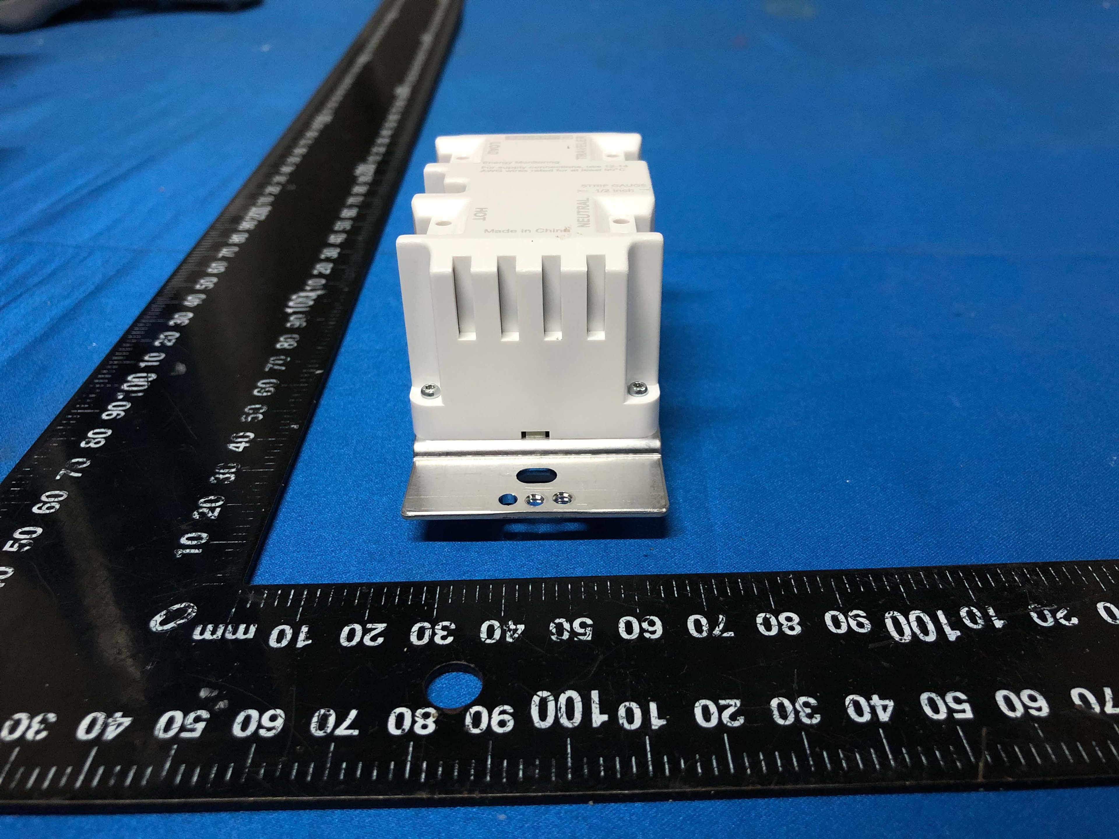
Click to zoom
Application Details
- Equipment Class
- DXX - Part 15 Low Power Communication Device Transmitter
- Date of Grant
- Jan 31, 2021
- Application Purpose
- Original Equipment
- Date of Application
- Jan 31, 2021
- Equipment Note
- Z-WAVE+ SWITCH SINGLE POLE
- Frequency Range
- 904.00000000 - 916.00000000
- Country
- China
Documents & Files
Document Text
Text extracted from the exhibit documents filed with the FCC. Open a document above to read the original.
Users Manual
Instruction Bulletin SQR14102**Z Z-Wave Plus Switch GDE87982_Eng © 2020 Schneider Electric All Rights Reserved 1 SQR14102**Z Z-Wave TM Plus Switch ** = color code: WH (white), LA (light almond), BK (black), GY (gray) Features • Wireless Z-Wave technology creates a mesh network for command and control interoperability with other Z-Wave compliant controllers and devices. • Manual and remote ON/OFF control of any connected lighting and other electrical load. • Programmable delayed OFF time. • 3 configurable “power ON state”. • Configurable child lockout feature which disables local control. • Support single pole or 3-way (multi-location) use. • Measure the energy usage of the connected loading, display the actual consumption (in W) and the accumulated power used (in kWh) in the user interface of the gateway. NOTE: • Power on state means the initial status of the device when it is powered on. • For multi-location applications, the traditional mechanical switch or Z-Wave wireless auxiliary switch SQR50101**Z could be used along with one Z- Wave Master Switch. • Please refer to the gateway installation manual for energy usage display and energy measurement features. Specification of SQR14102**Z Z-Wave Plus Switch, Single Pole, Energy Monitoring Voltage 120 Vac, 60 Hz Incandescent 1000 W LED 5 A Standard ballast 1200 Va Resistive 1800 W (15 A) Motor 1/2 Hp Operating temperature 32–104°F (0–40°C) Supply connection 14 AWG 1 Wireless type Z-Wave (Support S2 and SmartStart) Wireless frequency 908.40 MHz / 908.42 MHz / 916 MHz 1 Suitable for at least 90°C. Instruction Bulletin GDE77982_Eng, Instruction Bulletin SQR14102**Z Z-Wave Plus Switch GDE87982_Eng © 2020 Schneider Electric All Rights Reserved 2 Precautions CAUTION HAZARD OF UNINTENDED USE This device is intended to be used for non-critical automation activities. It is not intended to support life, safety, or medical equipment. Failure to follow these instructions can result in personal injury or equipment damage. DANGER HAZARD OF ELECTRIC SHOCK, EXPLOSION, OR ARC FLASH • Apply appropriate personal protective equipment (PPE) and follow safe electrical work practices. See NFPA 70E, NOM-029-STPS or CSA Z462 or local equivalent. • This equipment must only be installed and serviced by qualified electrical personnel. • Turn off all power supplying this equipment before working on or inside equipment. • Always use a properly rated voltage sensing device to confirm power is off. • Use with copper wire only. • Indoor use only. • Replace all devices, doors, and covers before turning on power to this equipment. Failure to follow these instructions will result in death or serious injury. WARNING HAZARD OF HEAT AND FIRE DAMAGE Read all instructions before installation. The manufacturer will not be held responsible for product damage resulting from not following the instructions. • Wet hands are strictly prohibited. • Work strictly according to the rated load. • Do not continue working after self-disassembly of any nature and damage of external forces. Failure to follow these instructions can result in death, injury or equipment damage. WARNING: This product can expose you to chemicals including Carbon black, which is known to the State of California to cause cancer, and Bisphenol A (BPA), which is known to the State of California to cause birth defects or other reproductive harm. For more information go to www.P65Warnings.ca.gov. Instruction Bulletin SQR14102**Z Z-Wave Plus Switch GDE87982_Eng © 2020 Schneider Electric All Rights Reserved 3 Notice Wireless Range Conditions The wireless range is the effective distance of remote control and it will be impacted by the following conditions: • Each wall or obstacle (e.g., refrigerator, TV, etc.) between the remote or Z- Wave device and the destination device will reduce the wireless range. • Brick, tile, or concrete walls block more of the wireless signal than walls made of wooden studs and plasterboard (drywall). • The angle of direction between the remote or Z-Wave device and the destination device will also impact the wireless range; normally, placing the Z- Wave devices face-to-face will get the best wireless range. • Wall-mounted Z-Wave devices installed in metal junction boxes may suffer a significant loss of range since the metal box blocks a large part of the wireless signal. Installation 1. Turn the power OFF at circuit breaker or fuse and test that power is off before wiring. 2. Wire the device according to the appropriate wiring diagram. 3. Check that all connections are tight and no bare wires exposed. 4. Install the device into the standard outlet box using the screws provided. (change the CR No. to SQR14102**Z) Instruction Bulletin SQR14102**Z Z-Wave Plus Switch GDE87982_Eng © 2020 Schneider Electric All Rights Reserved 4 (change the CR No. to SQR14102**Z) (Update the switch marking) (change ‘auxiliary switch’ to ‘Mechanical Switch’) (change the traditional switch drawing to be single-pole switch which has only 2 terminals) (add note for wire connect to ‘Traveler’ terminal) Note: For 3-way control along with Z-Wave auxiliary switch SQR50101**Z, there’s no wire between the Z-Wave master device and the auxiliary switch, please refer to the user manual of SQR50101**Z for the wiring diagram of the auxiliary switch itself. 5. Install the plate (not included). 6. Restore power. Instruction Bulletin SQR14102**Z Z-Wave Plus Switch GDE87982_Eng © 2020 Schneider Electric All Rights Reserved 5 Operation 1. Local control: One short tap on upper paddle: turn on the lighting One short tap on lower paddle: turn off the lighting (update the switch drawing by adding the reset button, remove unnecessary marking) 2. Group control the nodes of association group 2: Press upper and lower paddles at the same time for group on and group off. (change to switch drawing, and remove long press operation) NOTE: Please refer to association setting for nodes group 2 setup. This requires a gateway with advanced features and ass…
Text truncated - open the document above for the full version.
Cover Letter(s)
Schneider Electric (China) Co., Ltd., Shenzhen Branch Agent Authorization Company: Schneider Electric (China) Co., Ltd., Shenzhen Branch Address: Room 201, Building A, No. 1 Qianwanyi Road, Shengang Cooperation Zone, Qianhai, Shenzhen, China Product Name: Z-WAVE+ SWITCH SINGLE POLE Model Number(s): SQR14102WHZ;SQR14102LAZ;SQR14102BKZ Product Description: Z-WAVE+ SWITCH SINGLE POLE We authorize MiCOM Labs Inc., 575 Boulder Court, Pleasanton, California 94566, USA, to act on our behalf on all matters concerning the certification of above named equipment. We declare that MiCOM Labs Inc. is allowed to forward all information related to the approval and certification of equipment to the regulatory agencies as required and to discuss any issues concerning the approval application. Any and all acts carried out by MiCOM Labs on our behalf shall have the same effect as acts of our own. Signature: Date: Dec 1 st , 2020 Name: Tony Huang Title: Manager Company: Schneider Electric (China) Co., Ltd., Shenzhen Branch
Cover Letter(s)
Schneider Electric (China) Co., Ltd., Shenzhen Branch Address: Room 201, Building A, No. 1 Qianwanyi Road, Shengang Cooperation Zone, Qianhai, Shenzhen, China Confirmation Letter We, Schneider Electric (China) Co., Ltd., Shenzhen Branch The product: Z-WAVE+ SWITCH SINGLE POLE FCC ID: 2AUCU- 14102Z IC: 25381- 14102Z SQR14102LAZ and SQR14102BKZ have the same technical construction including circuit diagram, PCB Layout, components and component layout, all electrical construction and mechanical construction with SQR14102WHZ. The difference lies only model number and color. ______________________ Company Name: Schneider Electric (China) Co., Ltd., Shenzhen Branch Contact Name: Tony Huang Address: Room 201, Building A, No. 1 Qianwanyi Road, Shengang Cooperation Zone, Qianhai, Shenzhen Date:12/16/2020
Cover Letter(s)
Schneider Electric (China) Co., Ltd., Shenzhen Branch Dec 1 st , 2020 Federal Communications Commission Authorization and Evaluation Division FCC ID:2AUCU- 14102Z Confidentiality Request Pursuant to Sections 0.457 and 0.459 of the Commission’s Rules, the applicant hereby requests confidential treatment of information applied this application as outlined below: 1. Block Diagram 2. Circuit Diagram 3. Operational Description The above materials contain trade secrets and proprietary information not customarily released to the public. The public disclosure of these matters might be harmful to the applicant and provide unjustified benefits to its competitors. The Applicant understands that pursuant to Rule 0.457, disclosure of this Application and all accompanying documentation will not be made before the date of the Grant for this application Sincerely, Company Name: Schneider Electric (China) Co., Ltd., Shenzhen Branch Contact Name: Tony Huang Title of Person:Manager E-mail: [email protected] Address: Room 201, Building A, No. 1 Qianwanyi Road, Shengang Cooperation Zone, Qianhai, Shenzhen
External Photos
.... 厦莹莹到 .. 每量 - A气
ID Label/Location Info
} Original format A4 A B C D E F A B C D E F 1 2 34 State: 00 1/1 Document Number: Doc. Rev. Sheet: 1.000 mm Scale: Technical Specification: Units of measure : The information is highly confidential and is the exclusive property of Schneider Electric copyright reserved. This drawing must not be used for any purpose other than that expressly permitted in writing by the owners and must not be disclosed or reproduced in any way without permission from the owners in writing. This drawing must be returned to the owners when the purpose has ceased. Provisional NOTES: *** ARTWORK IS THE MASTER FOR COLOUR, FONT, SIZE & LOGO'S*** 1. TEST FOR MARKINGS: REFER TO CQCS 2. LOCATION OF MARKING: POSITION AS SHOWN 3. FONT: ARIAL ROUNDED 4. TEXT HEIGHT: AS INDICATED 5. SQUARE D LOGO SIZE: 2.73MM(H)*13.79MM(L)(Pantone Cool grey 6C) 6. MINIMUM SIZE: 0.5 inch (12.7mm) 1/2 inch (4 mm) (2.4 mm) 7. MINIMUM SIZE: (10 mm) Energy Monitoring SQR14102BKZ Resistive: 1800W (15A) Standard ballast: 1200VA lncandescent: 1000W LED: 5A Motor: 1/2HP 120VAC, 60Hz INDOOR USE ONLY YYYYMMDD XXXXX FONT SIZE: Reset STRIP GAUGE LOAD TRAVELER HOT NEUTRAL Made in China E515069 1/2 inch FCC ID : 2AUCU-14102Z CAN ICES-003(B)/NMB-003(B) IC: 25381-14102Z For supply connections, use 12-14 AWG wires rated for at least 90°C Z-WAVE S2 PIN Code XXXXX (10 mm) (11mm) 5. MINIMUM SIZE: (Z-WAVE Logo Color: Black) UL Label Original format A4 A B C D E F A B C D E F 1 2 34 State: 00 1/1 Document Number: Doc. Rev. Sheet: 1.000 mm Scale: Technical Specification: Units of measure : The information is highly confidential and is the exclusive property of Schneider Electric copyright reserved. This drawing must not be used for any purpose other than that expressly permitted in writing by the owners and must not be disclosed or reproduced in any way without permission from the owners in writing. This drawing must be returned to the owners when the purpose has ceased. Provisional NOTES: *** ARTWORK IS THE MASTER FOR COLOUR, FONT, SIZE & LOGO'S*** 1. TEST FOR MARKINGS: REFER TO CQCS 2. LOCATION OF MARKING: POSITION AS SHOWN 3. FONT: ARIAL ROUNDED 4. TEXT HEIGHT: AS INDICATED (WIRELESS SWITCH)
ID Label/Location Info
} Original format A4 A B C D E F A B C D E F 1 2 34 State: 00 1/1 Document Number: Doc. Rev. Sheet: 1.000 mm Scale: Technical Specification: Units of measure : The information is highly confidential and is the exclusive property of Schneider Electric copyright reserved. This drawing must not be used for any purpose other than that expressly permitted in writing by the owners and must not be disclosed or reproduced in any way without permission from the owners in writing. This drawing must be returned to the owners when the purpose has ceased. Provisional NOTES: *** ARTWORK IS THE MASTER FOR COLOUR, FONT, SIZE & LOGO'S*** 1. TEST FOR MARKINGS: REFER TO CQCS 2. LOCATION OF MARKING: POSITION AS SHOWN 3. FONT: ARIAL ROUNDED 4. TEXT HEIGHT: AS INDICATED 5. SQUARE D LOGO SIZE: 2.73MM(H)*13.79MM(L)(Pantone Cool grey 6C) 6. MINIMUM SIZE: 0.5 inch (12.7mm) 1/2 inch (4 mm) (2.4 mm) 7. MINIMUM SIZE: (10 mm) Energy Monitoring SQR14102LAZ Resistive: 1800W (15A) Standard ballast: 1200VA lncandescent: 1000W LED: 5A Motor: 1/2HP 120VAC, 60Hz INDOOR USE ONLY YYYYMMDD XXXXX FONT SIZE: Reset STRIP GAUGE LOAD TRAVELER HOT NEUTRAL Made in China E515069 1/2 inch FCC ID : 2AUCU-14102Z CAN ICES-003(B)/NMB-003(B) IC: 25381-14102Z For supply connections, use 12-14 AWG wires rated for at least 90°C Z-WAVE S2 PIN Code XXXXX (10 mm) (11mm) 5. MINIMUM SIZE: (Z-WAVE Logo Color: Black) UL Label Original format A4 A B C D E F A B C D E F 1 2 34 State: 00 1/1 Document Number: Doc. Rev. Sheet: 1.000 mm Scale: Technical Specification: Units of measure : The information is highly confidential and is the exclusive property of Schneider Electric copyright reserved. This drawing must not be used for any purpose other than that expressly permitted in writing by the owners and must not be disclosed or reproduced in any way without permission from the owners in writing. This drawing must be returned to the owners when the purpose has ceased. Provisional NOTES: *** ARTWORK IS THE MASTER FOR COLOUR, FONT, SIZE & LOGO'S*** 1. TEST FOR MARKINGS: REFER TO CQCS 2. LOCATION OF MARKING: POSITION AS SHOWN 3. FONT: ARIAL ROUNDED 4. TEXT HEIGHT: AS INDICATED (WIRELESS SWITCH)
ID Label/Location Info
} Original format A4 A B C D E F A B C D E F 1 2 34 State: 00 1/1 Document Number: Doc. Rev. Sheet: 1.000 mm Scale: Technical Specification: Units of measure : The information is highly confidential and is the exclusive property of Schneider Electric copyright reserved. This drawing must not be used for any purpose other than that expressly permitted in writing by the owners and must not be disclosed or reproduced in any way without permission from the owners in writing. This drawing must be returned to the owners when the purpose has ceased. Provisional NOTES: *** ARTWORK IS THE MASTER FOR COLOUR, FONT, SIZE & LOGO'S*** 1. TEST FOR MARKINGS: REFER TO CQCS 2. LOCATION OF MARKING: POSITION AS SHOWN 3. FONT: ARIAL ROUNDED 4. TEXT HEIGHT: AS INDICATED 5. SQUARE D LOGO SIZE: 2.73MM(H)*13.79MM(L)(Pantone Cool grey 6C) 6. MINIMUM SIZE: 0.5 inch (12.7mm) 1/2 inch (4 mm) (2.4 mm) 7. MINIMUM SIZE: (10 mm) Energy Monitoring SQR14102WHZ Resistive: 1800W (15A) Standard ballast: 1200VA lncandescent: 1000W LED: 5A Motor: 1/2HP 120VAC, 60Hz INDOOR USE ONLY YYYYMMDD XXXXX FONT SIZE: Reset STRIP GAUGE LOAD TRAVELER HOT NEUTRAL Made in China E515069 1/2 inch FCC ID : 2AUCU-14102Z CAN ICES-003(B)/NMB-003(B) IC: 25381-14102Z For supply connections, use 12-14 AWG wires rated for at least 90°C Z-WAVE S2 PIN Code XXXXX (10 mm) (11mm) 5. MINIMUM SIZE: (Z-WAVE Logo Color: Black) UL Label Original format A4 A B C D E F A B C D E F 1 2 34 State: 00 1/1 Document Number: Doc. Rev. Sheet: 1.000 mm Scale: Technical Specification: Units of measure : The information is highly confidential and is the exclusive property of Schneider Electric copyright reserved. This drawing must not be used for any purpose other than that expressly permitted in writing by the owners and must not be disclosed or reproduced in any way without permission from the owners in writing. This drawing must be returned to the owners when the purpose has ceased. Provisional NOTES: *** ARTWORK IS THE MASTER FOR COLOUR, FONT, SIZE & LOGO'S*** 1. TEST FOR MARKINGS: REFER TO CQCS 2. LOCATION OF MARKING: POSITION AS SHOWN 3. FONT: ARIAL ROUNDED 4. TEXT HEIGHT: AS INDICATED (WIRELESS SWITCH)
Test Report
TEST REPORT Applicant : Schneider Electric (China) Co., Ltd., Shenzhen Branch Product Name : Z-WAVE+ SWITCH SINGLE POLE Mode No. : SQR14102WHZ,SQR14102LAZ,SQ R14102BKZ Vkan Certification & Testing Co., Ltd. Add.: No.3, Tiantaiyi Road, Kaitai Avenue, Science City, Guangzhou, 510663, P. R. China Telephone: +86-20-32293888 Fax : +86-20-32293889 E-mail: [email protected] Test Report No.: FCC2020-0024-2 Vkan Certification & Testing Co., Ltd. CVC Test Report No. FCC2020-0024-2(XG1) Page 2 of 48 LTC-R-7092-RF-Part15C-A1 Applicant Name : Schneider Electric (China) Co., Ltd., Shenzhen Branch Address : Room 201, Building A, No. 1 Qianwanyi Road, Shengang Cooperation Zone, Qianhai, Shenzhen, China Manufacturer Name : Schneider Electric (China) Co., Ltd., Shenzhen Branch Address : Room 201, Building A, No. 1 Qianwanyi Road, Shengang Cooperation Zone, Qianhai, Shenzhen, China Equipment under Test Product Name : Z-WAVE+ SWITCH SINGLE POLE Model No. : SQR14102WHZ,SQR14102LAZ,SQR14102BKZ Trade mark : Schneider Electric,Square D Serial no. : — Sampling : — Date of Receipt. 2020.12.01 Date of Testing 2020.12.01~2021.01.27 Test Specification Test Result FCC CFR47 Part 15C (2020) Radio Frequency Devices ANSI C63.10 (2013) PASS Evaluation of Test Result The equipment under test was found to comply with the requirements of the standards applied. Issue Date: 2021.01.27 Tested by: Xu Zhenfei Name Signature Reviewed by: Liu Yonghai Name Signature Approved by: Zeng Bo Name Signature Other Aspects: NONE. Abbreviations:OK, Pass= passed Fail = failed N/A= not applicable EUT= equipment, sample(s) under tested This test report relates only to the EUT, and shall not be reproduced except in full, without written approval of CVC. Note: The report was originally issued on January 5, 2021, and was modified for the first time on January 28, 2021. The modification contents are as follows: the test block diagram of radiated emission is modified from "3m / 10m" to "3M"; the numbe r of punctuation points in the result diagram of all test items is modified from "3" to "6"; the antenna description is added to the test photos; the level value of the main frequency of radiated emission is marked; the modification is involved The page is the whole certification report with (XG1) symbol after the corresponding original report number. Vkan Certification & Testing Co., Ltd. CVC Test Report No. FCC2020-0024-2(XG1) Page 3 of 48 LTC-R-7092-RF-Part15C-A1 TABLE OF CONTENTS 1. GENERAL PRODUCT INFORMATION ................................................................................................ 4 1.1 GENERAL INFORMATION ............................................................................................................................. 4 2. TEST SITES ............................................................................................................................................ 5 2.1 TEST FACILITIES ......................................................................................................................................... 5 2.2 DESCRIPTION OF NON-STANDARD METHOD AND DEVIATIONS ................................................................. 5 2.3 LIST OF TEST AND MEASUREMENT INSTRUMENTS .................................................................................... 5 3. TEST CONFIGURATION ....................................................................................................................... 6 3.1 TEST MODE ................................................................................................................................................ 6 4. SUMMARY OF MEASUREMENT RESULTS ....................................................................................... 7 5. MEASUREMENT PROCEDURE .......................................................................................................... 8 5.1 AC POWER LINE CONDUCTED EMISSION .................................................................................................. 8 5.2 RADIATED EMISSION ................................................................................................................................ 16 5.3 OCCUPIED BANDWIDTH ............................................................................................................................ 36 5.4 ANTENNA MEASUREMENT ........................................................................................................................ 39 6. TEST SETUP PHOTOGRAPH ............................................................................................................. 40 7. EUT PHOTOGRAPH ............................................................................................................................ 42 8. APPENDIX ............................................................................................................................................ 48 Vkan Certification & Testing Co., Ltd. CVC Test Report No. FCC2020-0024-2(XG1) Page 4 of 48 LTC-R-7092-RF-Part15C-A1 1. General Product Information The model of this application: SQR14102WHZ, SQR14102LAZ, SQR14102BKZ. SQR14102LAZ and SQR14102BKZ have the same technical construction including circuit diagram, PCB Layout, components and component layout, all electrical construction and mechanical construction with SQR14102WHZ. The difference lies only model number and color. All the tests carried out on model SQR14102WHZ. 1.1 General information Product Name Z-WAVE + SWITCH SINGLE POLE Model No. SQR14102WHZ,SQR14102LAZ,SQR14102BKZ Power Supply 120 Vac,60Hz Antenna Type External Antenna Antenna Connector A permanently attached antenna (meet with the standard FCC Part 15.203 requirement) Antenna Gain Antenna 1:0.5dBi Wireless Frequency 908.4 MHz, 908.42 MHz, 916.00 MHz Modulation Type FSK, GFSK Data rate 9.6 kbps, 40 kbps, 100 kbps FCC ID 2AUCU-14102Z Note 1. The information of the EUT is declared by the manufacturer. Vkan Certification & Testing Co., Ltd. CVC Test Report N…
Text truncated - open the document above for the full version.
Contact Information
Applicant
Tony Huang
Technical Contact
Test Firm
CVC Testing Technology Co., Ltd.Lai Wenjing
[email protected]86 2032293684
Technical Specifications
| # | Rule Parts | Frequency Range | Power Output |
|---|---|---|---|
| 1 | 15C | 904 MHz - 916 MHz | - |
Other Applications from Schneider Electric (China) Co., Ltd., Shenzhen Branch

2AUCU-44102Z
Jun 30, 2021Z-WAVE+ 15A TR RECEPTACLE
Equipment Class
DXX - Part 15 Low Power Communication Device Transmitter
2AUCU-22102Z
Jun 30, 2021Z-WAVE+ 600W DIMMER SINGLE POLE
Equipment Class
JAB - Part 15 Class B Digital Device
2AUCU-62102Z
Jun 27, 2021Z-WAVE+ 15A PLUG-IN OUTLET
Equipment Class
DXX - Part 15 Low Power Communication Device Transmitter
2AUCU-441U1W
Apr 28, 2021WI-FI 15A TR RECEPTACLE
Equipment Class
DTS - Digital Transmission System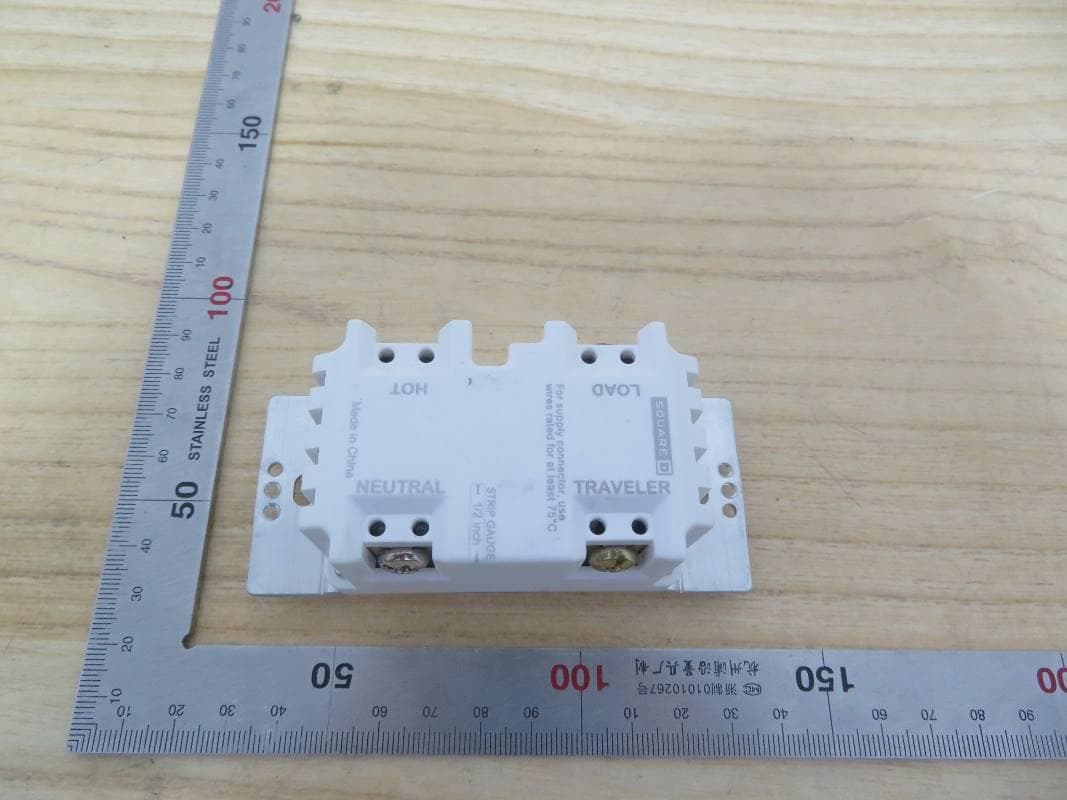
2AUCU-226U1W
Feb 23, 2021WI-FI 600W DIMMER SINGLE POLE
Equipment Class
DTS - Digital Transmission System