2AUCU-44101ZZ-Wave Receptacle
Schneider Electric (China) Co., Ltd., Shenzhen Branch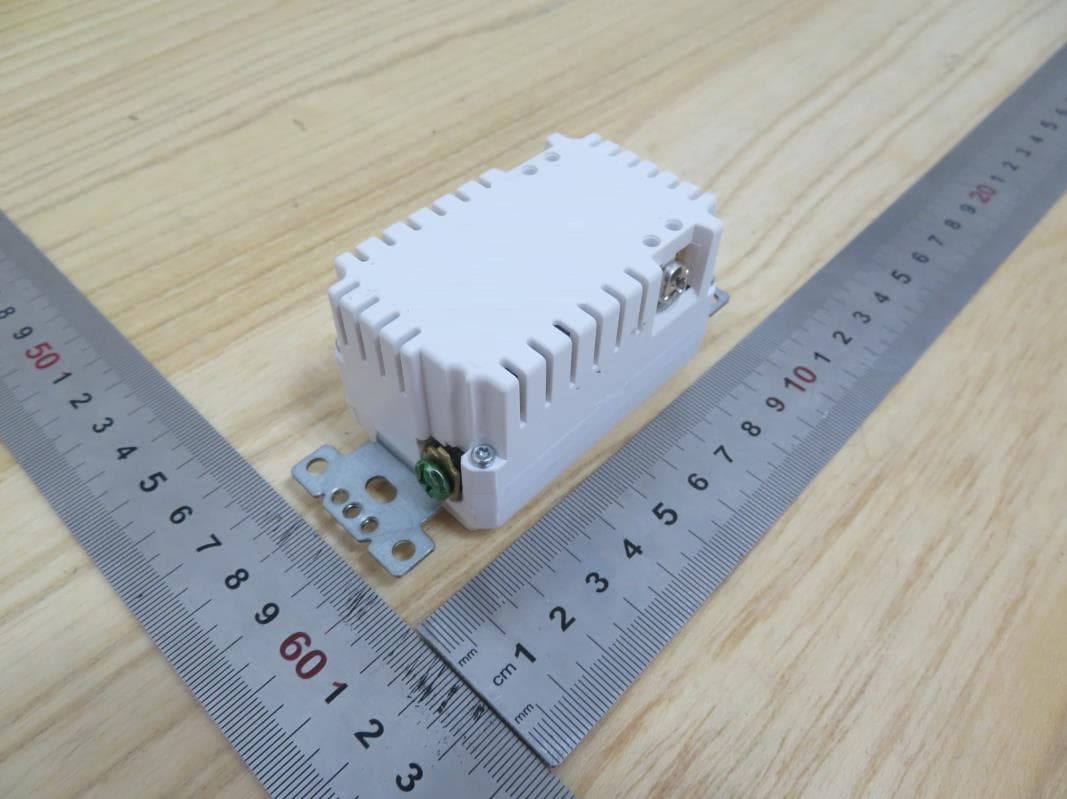
Click to zoom
Application Details
- Equipment Class
- DXT - Part 15 Low Power Transceiver, Rx Verified
- Date of Grant
- Jun 21, 2020
- Application Purpose
- Original Equipment
- Date of Application
- Jun 21, 2020
- Equipment Note
- Z-Wave Receptacle
- Frequency Range
- 908.40000000 - 916.00000000
- Country
- China
Documents & Files
Document Text
Text extracted from the exhibit documents filed with the FCC. Open a document above to read the original.
Users Manual
INSTALLATION INSTRUCTIONS ♦OPERATIONS This application guide applies to the following products. -01- -02- -03- SQR44101WHZ,SQR44101LAZ,SQR44101BKZ Z-WAVE TR RECEPTACLE ENERGY MONITORING 15A 125VAC FCC ID: 2AUCU-44101Z IC: 25381-44101Z CAN ICES-3(B)/NMB-3(B) ♦SPECIFICATIONS Regular Outlet Voltage ..................................................................................................... 125VAC, 60Hz Current.......................................................................................................15A Controlled Outlet Voltage..........................................................................................125VAC, 60Hz Incandescent ........................................................................................................... 1000W LED ................................................................................................................................. 5A Standard Ballast ..................................................................................................... 1200VA Resistive ......................................................................................................... 1800W(15A) Motor ..................................................................................................................... 1/2 HP Operating Temperature .............................................................. 32°F〜104°F(0°C~40°C) Supply Connection............................................14AWG wires rated for at least 90°C Screw Torque....................................................................................12-14 Ibf-in Wireless Type....................................................................................... Z-wave Wireless Frequency.............................................. 908.40MHz/908.42MHz/916MHz Wireless range ................................................80 feet in open air and line of sight ♦INSTALLATION STEP1 Turn Power Off. Indoor use only. STEP 2 Connect the device as shown in the wiring diagram: Black lead to hot wire, white lead to neutral wire, Black lead to load wire, green lead to ground wire. STEP 3 Check connections to be sure they are tight and no bare conductors are exposed. STEP 4 Insert the device into the standard outlet box carefully. STEP 5 Make sure the device is fixed to the box using the supplied screws. STEP 6 Install the wall plate (not included) following below figure STEP 7 Restore power at the circuit breaker. ♦FEATURES •Wireless Z-Wave technology creates a mesh network for command and control interoperability with other Z-Wave compliant controller and devices •Manual and Remote ON/OFF control of any lighting or other electrical load connected to Z-wave controlled outlet •Tamper-Resistant •Measure the energy usage of the connected loading on the z-wave controlled outlet, display the actual consumption (in W) and the accumulated power used (in kWh) in the user interface of the gateway. Notice: for energy measurement feature, please refer to the gateway installation manual for energy usage display. WARNING: CALIFORNIA PROPOSITION 65 This product can expose you to chemicals including Carbon black, which is known to the State of California to cause cancer, and Bisphenol A (BPA), which is known to the State of California to cause birth defects or other reproductive harm. For more information go to www.P65Warnings.ca.gov WARNING Be sure to read the instruction carefully before installation, and the manufacturer will not be responsible for any product damage that does not follow the instruction 1.Wet hands are strictly prohibited. 2.Must work strictly according to the rated load. 3.Do not continue to work after self-disassembly of any nature and damage of external forces. 4.Copper cable only 5.Indoor use only 1.Local control: Press the program button, the appliance or device plugged into Z-Wave controlled outlet will turn ON or OFF. Notice: After a power failure, the device returns to OFF state. 2.Join/Leave Z-Wave network. When the gateway is in adding mode or removing mode, press and hold the program button for more than 3 seconds. Notice: Please also refer to the instruction of the z-wave gateway for the operations on gateway itself. 3.Remote control Z-Wave remotes can provide control of an Individual device, Groups of devices and Scenes, depends on the flexibility in how you set up your lighting control network. Please refer to your gateway’s instruction for details. Notices for wireless range: The wireless range is the effective distance of remote control, and it will be impacted by following conditions. •Each wall or obstacle (i.e. refrigerator, big screen TV, etc.) between the remote or Z-Wave device and the destination device will reduce the wireless range. •Brick, tile or concrete walls block more of the wireless signal than walls made of wooden studs and plasterboard (drywall). •The direction angle between remote or Z-wave device and the destination device will also impact the wireless range, normally put the Z-wave devices face to face will get the best wireless range. •Wall mounted Z-Wave devices installed in metal junction boxes may suffer a significant loss of range since the metal box blocks a large part of the wireless signal. 4.Reset to factory defaults Press the program button and hold for more than 10 seconds. ADVANCED SETTING The following Advanced setting requires an advanced gateway. Basic gateway does not support his setting. Users can do the setting through the interface of the advanced gateway. All Configuration Parameters can all be restored to their factory default settings by the gateway or by manual reset. Configuration Parameter No. Size Description Valid Value Default Value 1 1 Byte Synchronization of outlet power and LED indicator 0: Power on, LED off Default=0 1: Power on, LED on Association Grouping ID Max number of nodes Description 1 1 Lifeline: Send device reset locally notification 2 5 StatusReport: Send basic report 3 5 PowerReport: Send me…
Text truncated - open the document above for the full version.
Cover Letter(s)
Schneider Electric (China) Co., Ltd., Shenzhen Branch Federal Communications Commission 7435 Oakland Mills Road Columbia MD 21046 Subject: Request for Confidentiality FCC ID: 2AUCU-44101Z To Whom It May Concern: Pursuant to the provisions of Sections 0.457 and 0.459 of the Commission’s rules (47 CFR §§ 0.457, 0.459), we are requesting the Commission to withhold the following attachments as confidential document from public disclosure indefinitely. Schematic Diagram Block Diagram Theory of Operation Above mentioned document contains detailed system and equipment description are considered as proprietary information in operation of the equipment. The public disclosure of above documents might be harmful to our company and would give competitor an unfair advantage in the market. It is our understanding that all measurement test reports, FCC ID label format and correspondent during certification review process cannot be granted as confidential documents and those information will be available for public review once the grant of equipment authorization is issued. Best Regards Company Name: Schneider Electric (China) Co., Ltd., Shenzhen Branch Contact Name: Tony Huang Title of Person:Manager Address: Room 201, Building A, No. 1 Qianwanyi Road, Shengang Cooperation Zone, Qianhai, Shenzhen Date:01/21/2020
Cover Letter(s)
Schneider Electric (China) Co., Ltd., Shenzhen Branch Address: Room 201, Building A, No. 1 Qianwanyi Road, Shengang Cooperation Zone, Qianhai, Shenzhen, China Confirmation Letter We, Schneider Electric (China) Co., Ltd., Shenzhen Branch The product: Z-Wave Receptacle FCC ID: 2AUCU-44101Z IC: 25381-44101Z SQR44101LAZ, SQR44101BKZ have the same technical construction including circuit diagram, PCB Layout, components and component layout, all electrical construction and mechanical construction with SQR44101WHZ.The difference lies only model number and color. Company Name: Schneider Electric (China) Co., Ltd., Shenzhen Branch Contact Name: Tony Huang Address: Room 201, Building A, No. 1 Qianwanyi Road, Shengang Cooperation Zone, Qianhai, Shenzhen Date:06/04/2020
External Photos
Appendix I External Photographs Page 2 of 3 UL Verification Services (Guangzhou) Co., Ltd, Song Shan Lake Branch This report shall not be reproduced except in full, without the written approval of UL Verification Services (Guangzhou) Co., Ltd, Song Shan Lake Branch. . View of EUT-1 View of EUT-2 Page 3 of 3 UL Verification Services (Guangzhou) Co., Ltd, Song Shan Lake Branch This report shall not be reproduced except in full, without the written approval of UL Verification Services (Guangzhou) Co., Ltd, Song Shan Lake Branch. . View of EUT-3 View of EUT-4
ID Label/Location Info
} Original format A4 A B C D E F A B C D E F 1 2 34 State: 00 1/1 Document Number: Doc. Rev. Sheet: 1.000 mm Scale: Technical Specification: Units of measure : The information is highly confidential and is the exclusive property of Schneider Electric copyright reserved. This drawing must not be used for any purpose other than that expressly permitted in writing by the owners and must not be disclosed or reproduced in any way without permission from the owners in writing. This drawing must be returned to the owners when the purpose has ceased. Provisional NOTES: *** ARTWORK IS THE MASTER FOR COLOUR, FONT, SIZE & LOGO'S*** 1. TEST FOR MARKINGS: REFER TO CQCS 2. LOCATION OF MARKING: POSITION AS SHOWN 3. FONT: ARIAL ROUNDED 4. TEXT HEIGHT: AS INDICATED 5. SQUARE D LOGO SIZE: 2.73MM(H)*13.79MM(L)(Pantone Cool grey 6C) GDE6614305 6. MINIMUM SIZE: (10 mm) (6 mm) 0.5 inch (12.7mm) 1/2 inch (11mm) 7. MINIMUM SIZE: (Z-WAVE Logo Color: Black) } Controlled E513975 SQR44101BKZ YYYYMMDD 15A 125VAC Firmware Version: X.XX 125VAC, 60HZResistive: 1875W(15A)Incandescent: 1000WStandard ballast: 1200VAMotor: 1/2 HPLED: 5A Energy Monitoring STRIP GAUGE 1/2 inch IC: 25381-44101ZCAN ICES-3(B)/NMB-3(B)For supply connections,use 12-14 AWG wires rated for at least 90°CFCC ID: 2AUCU-44101Z E513975 Made in China NEUTRAL HOT UL 498B S A IFETEL ID: XXXXXX Indoor Use OnlyUso solo en interiors Z-WAVE S2 PIN Code XXXXX 8. MINIMUM SIZE: (10 mm) (10 mm) FONT SIZE: XXXXX } Original format A4 A B C D E F A B C D E F 1 2 34 State: 00 1/1 Document Number: Doc. Rev. Sheet: 1.000 mm Scale: Technical Specification: Units of measure : The information is highly confidential and is the exclusive property of Schneider Electric copyright reserved. This drawing must not be used for any purpose other than that expressly permitted in writing by the owners and must not be disclosed or reproduced in any way without permission from the owners in writing. This drawing must be returned to the owners when the purpose has ceased. Provisional NOTES: *** ARTWORK IS THE MASTER FOR COLOUR, FONT, SIZE & LOGO'S*** 1. TEST FOR MARKINGS: REFER TO CQCS 2. LOCATION OF MARKING: POSITION AS SHOWN 3. FONT: ARIAL ROUNDED 4. TEXT HEIGHT: AS INDICATED 5. SQUARE D LOGO SIZE: 2.73MM(H)*13.79MM(L)(Pantone Cool grey 6C) GDE6614305 6. MINIMUM SIZE: (10 mm) (6 mm) 0.5 inch (12.7mm) 1/2 inch (11mm) 7. MINIMUM SIZE: (Z-WAVE Logo Color: Black) } Controlled E513975 SQR44101LAZ YYYYMMDD 15A 125VAC Firmware Version: X.XX 125VAC, 60HZResistive: 1875W(15A)Incandescent: 1000WStandard ballast: 1200VAMotor: 1/2 HPLED: 5A Energy Monitoring STRIP GAUGE 1/2 inch IC: 25381-44101ZCAN ICES-3(B)/NMB-3(B)For supply connections,use 12-14 AWG wires rated for at least 90°CFCC ID: 2AUCU-44101Z E513975 Made in China NEUTRAL HOT UL 498B S A IFETEL ID: XXXXXX Indoor Use OnlyUso solo en interiors Z-WAVE S2 PIN Code XXXXX 8. MINIMUM SIZE: (10 mm) (10 mm) FONT SIZE: XXXXX } Original format A4 A B C D E F A B C D E F 1 2 34 State: 00 1/1 Document Number: Doc. Rev. Sheet: 1.000 mm Scale: Technical Specification: Units of measure : The information is highly confidential and is the exclusive property of Schneider Electric copyright reserved. This drawing must not be used for any purpose other than that expressly permitted in writing by the owners and must not be disclosed or reproduced in any way without permission from the owners in writing. This drawing must be returned to the owners when the purpose has ceased. Provisional NOTES: *** ARTWORK IS THE MASTER FOR COLOUR, FONT, SIZE & LOGO'S*** 1. TEST FOR MARKINGS: REFER TO CQCS 2. LOCATION OF MARKING: POSITION AS SHOWN 3. FONT: ARIAL ROUNDED 4. TEXT HEIGHT: AS INDICATED 5. SQUARE D LOGO SIZE: 2.73MM(H)*13.79MM(L)(Pantone Cool grey 6C) GDE6614305 6. MINIMUM SIZE: (10 mm) (6 mm) 0.5 inch (12.7mm) 1/2 inch (11mm) 7. MINIMUM SIZE: (Z-WAVE Logo Color: Black) } Controlled E513975 SQR44101WHZ YYYYMMDD 15A 125VAC Firmware Version: X.XX 125VAC, 60HZResistive: 1875W(15A)Incandescent: 1000WStandard ballast: 1200VAMotor: 1/2 HPLED: 5A Energy Monitoring STRIP GAUGE 1/2 inch IC: 25381-44101ZCAN ICES-3(B)/NMB-3(B)For supply connections,use 12-14 AWG wires rated for at least 90°CFCC ID: 2AUCU-44101Z E513975 Made in China NEUTRAL HOT UL 498B S A IFETEL ID: XXXXXX Indoor Use OnlyUso solo en interiors Z-WAVE S2 PIN Code XXXXX 8. MINIMUM SIZE: (10 mm) (10 mm) FONT SIZE: XXXXX
Internal Photos
Appendix II Internal Photographs Page 2 of 6 UL Verification Services (Guangzhou) Co., Ltd, Song Shan Lake Branch This report shall not be reproduced except in full, without the written approval of UL Verification Services (Guangzhou) Co., Ltd, Song Shan Lake Branch. . Open View of EUT Internal View of EUT-1 Antenna location Page 3 of 6 UL Verification Services (Guangzhou) Co., Ltd, Song Shan Lake Branch This report shall not be reproduced except in full, without the written approval of UL Verification Services (Guangzhou) Co., Ltd, Song Shan Lake Branch. . Internal View of EUT-2 Internal View of EUT-3 Page 4 of 6 UL Verification Services (Guangzhou) Co., Ltd, Song Shan Lake Branch This report shall not be reproduced except in full, without the written approval of UL Verification Services (Guangzhou) Co., Ltd, Song Shan Lake Branch. . Internal View of EUT-4 Internal View of EUT-5 Antenna Page 5 of 6 UL Verification Services (Guangzhou) Co., Ltd, Song Shan Lake Branch This report shall not be reproduced except in full, without the written approval of UL Verification Services (Guangzhou) Co., Ltd, Song Shan Lake Branch. . Internal View of EUT-6 Internal View of EUT-7 Page 6 of 6 UL Verification Services (Guangzhou) Co., Ltd, Song Shan Lake Branch This report shall not be reproduced except in full, without the written approval of UL Verification Services (Guangzhou) Co., Ltd, Song Shan Lake Branch. . Internal View of EUT-8
Test Report
The results reported herein have been performed in accordance with the laboratory’s terms of accreditation. This report shall not be reproduced except in full without the written approval of the Laboratory. The results in this report apply to the test sample(s) mentioned above at the time of the testing period only and are not to be used to indicate applicability to other similar products. This report does not imply that the product(s) has met the criteria for certification. FCC 47 CFR PART 15 SUBPART C ISED RSS-210 ISSUE 10 CERTIFICATION TEST REPORT For Z-Wave Receptacle MODEL NUMBER: SQR44101WHZ; SQR44101LAZ; SQR44101BKZ FCC ID: 2AUCU-44101Z IC: 25381-44101Z REPORT NUMBER: 4789339761-2 ISSUE DATE: June 01, 2020 Prepared for Schneider Electric (China) Co., Ltd., Shenzhen Branch Room 201, Building A, No. 1 Qianwanyi Road, Shengang Cooperation Zone, Qianhai, Shenzhen, China Prepared by UL Verification Services (Guangzhou) Co., Ltd, Song Shan Lake Branch Room 101, Building 10, Innovation Technology Park, Song Shan Lake Hi tech Development Zone, Dongguan, 523808, China Tel: +86 769 33817100 Fax: +86 769 33244054 Website: www.ul.com REPORT NO.: 4789339761-2 Page 2 of 42 UL Verification Services (Guangzhou) Co., Ltd, Song Shan Lake Branch FORM NO: 10-SL-F0035 This report shall not be reproduced except in full, without the written approval of UL Verification Services (Guangzhou) Co., Ltd, Song Shan Lake Branch. . Revision History Rev. Issue Date Revisions Revised By V0 06/01/2020 Initial Issue REPORT NO.: 4789339761-2 Page 3 of 42 UL Verification Services (Guangzhou) Co., Ltd, Song Shan Lake Branch FORM NO: 10-SL-F0035 This report shall not be reproduced except in full, without the written approval of UL Verification Services (Guangzhou) Co., Ltd, Song Shan Lake Branch. . TABLE OF CONTENTS 1. ATTESTATION OF TEST RESULTS ................................................................................. 4 2. TEST METHODOLOGY ..................................................................................................... 5 3. FACILITIES AND ACCREDITATION ................................................................................. 5 4. CALIBRATION AND UNCERTAINTY ................................................................................ 6 4.1. MEASURING INSTRUMENT CALIBRATION .............................................................. 6 4.2. MEASUREMENT UNCERTAINTY ............................................................................... 6 5. EQUIPMENT UNDER TEST ............................................................................................... 7 5.1. DESCRIPTION OF EUT .............................................................................................. 7 5.2. MAXIMUM EMISSIONS FIELD STRENGTH ............................................................... 7 5.3. THE WORSE CASE POWER SETTING PARAMETER ............................................... 8 5.4. TEST ENVIRONMENT ................................................................................................ 8 5.5. TEST CHANNEL CONFIGURATION ........................................................................... 8 5.6. DESCRIPTION OF AVAILABLE ANTENNAS .............................................................. 9 5.7. DESCRIPTION OF TEST SETUP ................................................................................ 9 5.8. MEASURING INSTRUMENT AND SOFTWARE USED ..............................................10 6. SUMMARY OF TEST RESULTS .......................................................................................11 7. ANTENNA PORT TEST RESULTS ...................................................................................12 7.1. ON TIME AND DUTY CYCLE .....................................................................................12 7.2. 20 dB AND 99% BANDWIDTH ...................................................................................13 8. RADIATED TEST RESULTS .............................................................................................16 8.1. LIMITS AND PROCEDURE ........................................................................................16 8.2. FIELD STRENGTH OF INTENTIONAL EMISSIONS ..................................................22 8.3. SPURIOUS EMISSIONS BELOW 30M .......................................................................28 8.4. SPURIOUS EMISSIONS BELOW 1 GHz ....................................................................31 8.5. SPURIOUS EMISSIONS 1 ~ 10GHz ..........................................................................33 9. AC POWER LINE CONDUCTED EMISSIONS ..................................................................39 10. ANTENNA REQUIREMENTS ........................................................................................42 REPORT NO.: 4789339761-2 Page 4 of 42 UL Verification Services (Guangzhou) Co., Ltd, Song Shan Lake Branch FORM NO: 10-SL-F0035 This report shall not be reproduced except in full, without the written approval of UL Verification Services (Guangzhou) Co., Ltd, Song Shan Lake Branch. . 1. ATTESTATION OF TEST RESULTS Applicant Information Company Name: Schneider Electric (China) Co., Ltd., Shenzhen Branch Address: Room 201, Building A, No. 1 Qianwanyi Road, Shengang Cooperation Zone, Qianhai, Shenzhen, China Manufacturer Information Company Name: Schneider Electric (China) Co., Ltd., Shenzhen Branch Address: Room 201, Building A, No. 1 Qianwanyi Road, Shengang Cooperation Zone, Qianhai, Shenzhen, China EUT Information EUT Name: Z-Wave Receptacle Model: SQR44101WHZ Series Models: SQR44101LAZ; SQR44101BKZ Model differences: SQR44101WHZ; SQR44101LAZ; SQR44101BKZ are identical except for color Brand Name: Sample Status: Normal Sample Received Date: Jan 17, 2020 Date of Tested: Jan 17~June 01, 2020 APPLICABLE STANDARDS STANDARD TEST RESULTS CFR 47 Part 15 Subpart C PASS ISED RSS-210 Issue 10 PASS ISED RSS-GEN Issue 5 PASS Prepared By: Checked By: Kebo Zhang Shawn…
Text truncated - open the document above for the full version.
Test Setup Photos
Appendix II Setup Photographs RADIATED RF MEASUREMENT SETUP (ABOVE 1 GHz) MEASUREMENT POSITION (X axis) MEASUREMENT POSITION (Y axis) MEASUREMENT POSITION (Z axis) RADIATED RF MEASUREMENT SETUP (30MHz~1GHz) RADIATED RF MEASUREMENT SETUP (Below 30MHz) POWERLINE CONDUCTED EMISSIONS MEASUREMENT SETUP
Contact Information
Applicant
Tony Huang
Test Firm
UL Verification Services (Guangzhou) Co., Ltd.Stephen Guo
[email protected]+86 0769 33817120
Technical Specifications
| # | Rule Parts | Frequency Range | Power Output |
|---|---|---|---|
| 1 | 15C | 908.4 MHz - 916 MHz | - |
Other Applications from Schneider Electric (China) Co., Ltd., Shenzhen Branch

2AUCU-44102Z
Jun 30, 2021Z-WAVE+ 15A TR RECEPTACLE
Equipment Class
DXX - Part 15 Low Power Communication Device Transmitter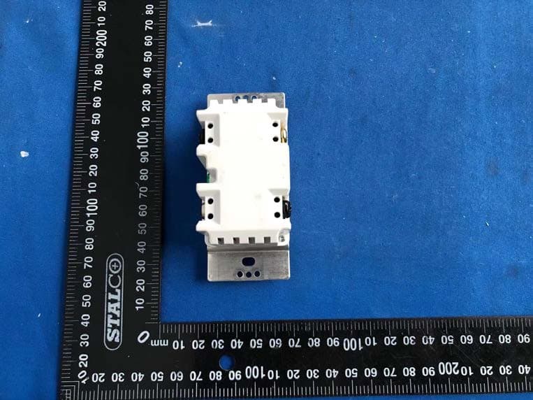
2AUCU-22102Z
Jun 30, 2021Z-WAVE+ 600W DIMMER SINGLE POLE
Equipment Class
JAB - Part 15 Class B Digital Device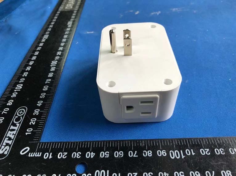
2AUCU-62102Z
Jun 27, 2021Z-WAVE+ 15A PLUG-IN OUTLET
Equipment Class
DXX - Part 15 Low Power Communication Device Transmitter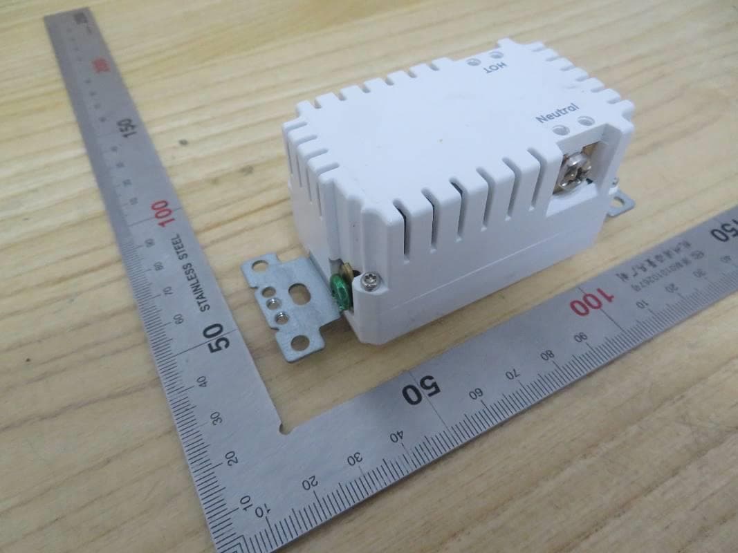
2AUCU-441U1W
Apr 28, 2021WI-FI 15A TR RECEPTACLE
Equipment Class
DTS - Digital Transmission System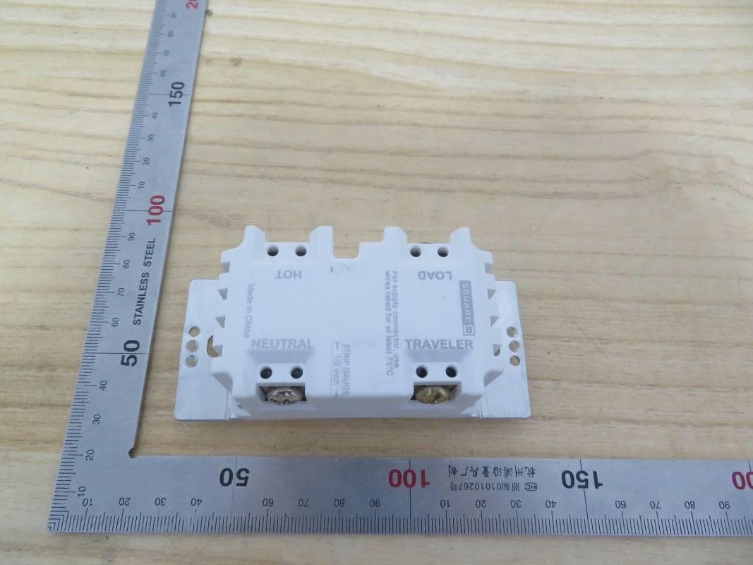
2AUCU-226U1W
Feb 23, 2021WI-FI 600W DIMMER SINGLE POLE
Equipment Class
DTS - Digital Transmission System