2AVCWMWC-21435G NR-U Wireless Bridge
Miliwave Co., Ltd.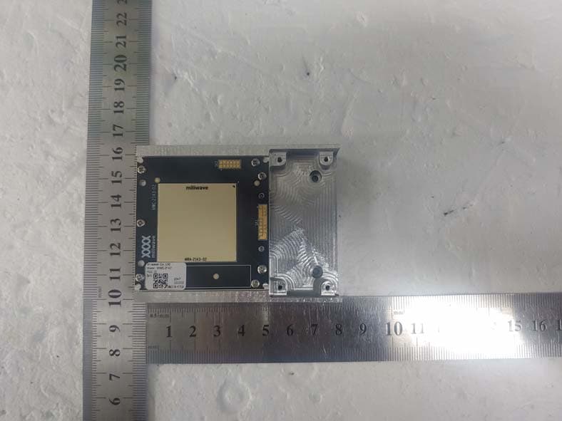
Click to zoom
Application Details
- Equipment Class
- DXX - Part 15 Low Power Communication Device Transmitter
- Date of Grant
- Feb 13, 2024
- Application Purpose
- Original Equipment
- Date of Application
- Feb 13, 2024
- Equipment Note
- 5G NR-U Wireless Bridge
- Frequency Range
- 58320.00000000 - 69120.00000000
- Company
- Miliwave Co., Ltd.
- Country
- South Korea
Documents & Files
Document Text
Text extracted from the exhibit documents filed with the FCC. Open a document above to read the original.
Users Manual
MWC-2143 User Manual 1 / 6 MWC-2143 User Manual 5G NR-U Wireless Module Rev. 1.0 2024-01-23 MWC-2143 User Manual 2 / 6 Revision History Date Written by Rev. Description 24.01.23 Sun.Lee 1.0 MWC-2143 User manual v1.0 release Address: Room 504, 106-40 Gwahakdnji-ro, Gangneung-si, Gangwon-do. 25440 KOREA. http://www.miliwave.co.kr/ Tel. 070-8825-0630 Fax. Email: [email protected] Copyright © Miliwave Inc. 2023. All rights reserved. No part of this document may be reproduced or transmitted in any form or by any means without prior written consent of Miliwave Co., Ltd. All specification supplied herein are subject to change without notice at any time. MWC-2143 User Manual 3 / 6 1.Introduction 1.1 Overview Miliwave’s MWC-2143 module operates in the 60GHz unlicensed frequency band, IEEE802.11ad compliant, and is designed for wireless bridge communication, primarily for Line-of Sight (LOS) operation. The MWC-2143 module connects to a Linux based Host Communication Processor board via an available 34pin receptable connector. All required drivers and firmware is pre-installed on the MWC- 2143 module as a self-contained device . However, the MWC-2143 module would not be operational unless it is connected to the Linux-based Host Communication Processor board for wireless bridge communication. For more information, please contact Miliwave ([email protected]) <Figure 1. MWC-2143 Module> MWC-2143 User Manual 4 / 6 1.2 Abbreviations and Acronym Definitions Acronym Definition Gbps Giga bits per second Mbps Mega bits per second GHz Giga Hertz IEEE Institute of Electrical and Electronics Engineers LED Light Emitting Diode Los Line of Sight MCS Modulation and Coding Scheme MHz Mega Hertz PTP Point to Point Communication QAM Quadrature amplitude modulation 1.3 MWC-2143 Module Description The Miliwave's MWC-2143 module in conjunction with the Host Communication Processor board can function as wireless bridge communication . Main chracteristics of the MWC-2143 module include: - Adaptive Modulation and Link Adaptation: Up to 16QAM and MCS0-12 support - Transmit power : EIRP max 39 dBm (with dish type antenna) - Scan Range : ±20° (Azimuth), ±15° (Elevation) - Advanced Security: AES-128 - Connectivity: 34pin Receptacle Connector. Receptacle Connector PN : “BM28B0.6-34DS/2-0.35V(51)” Matched Header Connector is “BM28B0.6-34DP/2-0.35V(53)” 2. Technical Specifications - Capacity: Max 2.5Gbps - Latency : less than 1 millisecond round-trip - Security: AES-128 - I/O interface: 34pin Receptacle Connector. (PN:BM28B0.6-34DS/2-0.35V(51)) 3.0 Radio Specifications - Access Technlogy: Single Carrier beam-forming physical layer - Frequencies: 58.32GHz ~ 69.12GHz (CH1~CH6) - Channel Bandwidth: 2.16 GHz - Antenna: PCB Antenna - EIRP: max 39 dBm 4.0 Mechanical, Power and Environmental Specification - Dimension: 50mm x 50 x 4mm - Weight: 15g - Power Consumption: 14W(Max) - Operating Temperature: -40ºC ~ +85ºC - Humidity: 5%~95% MWC-2143 User Manual 5 / 6 5.0 Module Throughput - MCS Index : 0-12, - Modulation: BPSK,QPSK,16QAM - Data Rate : Max PHY rate 4620 Mbit/s 6.0 Installation The MWC-2143 could only be installed with Host Communication Processor board at the factory level. There is no user serviceable parts in the MWC-2143 module. The MWC-2143 module would not be operational unless it is connected to the Linux-based Host Communication Processor board for wireless bridge communication. To connect to the host communication processor board, connect through the MWC-2143’s 34pin Receptacle Connector interface (PN : BM28B0.6-34DS/2-0.35V(51), Matched Header Connector is “BM28B0.6-34DP/2-0.35V(53)”). The component surface must be shielded with metal using a heatsink, and sufficient heat sink must be used to dissipate heat according to the power consumption. 7.0 FCC Statement This device complies with Part 15 of the FCC Rules. Operation is subject to the following two conditions: (1) This device may not cause harmful interference, and (2) this device must accept any interference received, including interference that may cause undesired operation. FCC Caution: Any changes or modifications not expressly approved by the party responsible for compliance could void the user's authority to operate this equipment. The antenna(s) must be installed such that a minimum separation distance of at least 25.15 cm is maintained between the radiator (antenna) and all persons at all times. 8.0 INTEGRATION INSTRUCTIONS List of applicable FCC rules This module complies with part 15.255 of the FCC rules. Summarize the specific operational use conditions This device is not to be operated on aircraft except for the conditions listed on FCC CFR § 15.255 (b). Typical Host Device Use cases MWC-2143 Module is designed for outdoor fixed wireless host device such as Point to Point Broadband, Broadband Mesh, and 60GHz to the Home. For more information, please contact your Miliwave ([email protected]) MWC-2143 User Manual RF exposure considerations This module complies with FCC RF radiation exposure limits set forth for an uncontrolled environment. The module is limited to installation in mobile or fixed applications. At least 25.15 cm of separation distance between the transmitting antenna and the user’s body must be maintained at all times. The host manual shall include the RF exposure statements. If RF exposure statements and use conditions are not provided, then the host product manufacturer is required to take responsibility of the module through a change in FCC ID (new application). Antennas The module itself has antenna. Label and compliance information The module is labeled with its own FCC. If the FCC ID is not visible when the module is installed inside another device, then the outside of the device into which the module is installed must also display a label referring to the enclosed module. In that case, the final end product must be labeled in a visible area with the following: “Contains FCC ID: 2AVCWMWC-2143 ” The host manual shall includ…
Text truncated - open the document above for the full version.
External Photos
FCC ID: 2AVCWMWC-2143 Copyright Ⓒ 2024, Dt&C Co., Ltd. View 1 FCC ID: 2AVCWMWC-2143 Copyright Ⓒ 2024, Dt&C Co., Ltd. View 2 FCC ID: 2AVCWMWC-2143 Copyright Ⓒ 2024, Dt&C Co., Ltd. View 3
Internal Photos
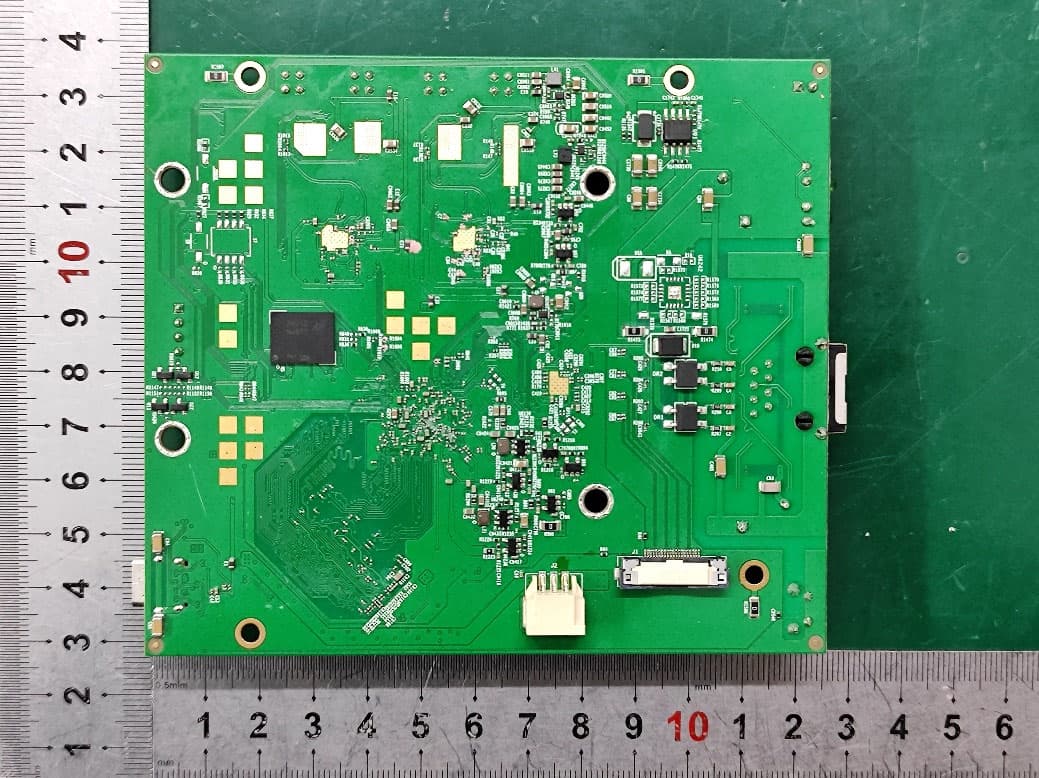
FCC ID: 2AVCWMWC-2143 Copyright Ⓒ 2024, Dt&C Co., Ltd. View 1 FCC ID: 2AVCWMWC-2143 Copyright Ⓒ 2024, Dt&C Co., Ltd. View 2 Antenna
RF Exposure Info
FCC ID: 2AVCWMWC-2143 RF feature(Mode) Separation distance(cm) Max. tune-up EIRP (dBm) Note1 Maximum EIRP (mW) Maximum power density(mW/cm 2 ) Requirement (mW/cm 2 ) 802.11ad 58 320.0 ~ 69 120.0 25.15 39.00 7 943.3 0.999 4 1.000 ~~~~~~~ ▪ S = - Note = / ( 4 X R 2 X π ) = mW/cm 2 Electric Field strength (V/m) Magnetic field strength (A/m) Power Density (mW/cm 2 ) Averaging time (minutes) 0.3 ~ 1.34 614 1.63 *100 30 1.34 ~ 30 824/f 2.19 / f *180 / f 2 30 30 ~ 300 27.5 0.073 0.2 30 300 ~ 1,500 f / 1500 30 1,500 ~ 100,000 1.0 30 Conclusion : Method: KDB447498 D01v06 Note2: To comply with RF exposure requirements, a minimum separ ation distance of 25.15cm mus t be maintained between the antenn a and the body of the user. R= Distance to the center of the radiation of the antenna(25.15 cm ) Frequency range (MHz) The MPE sample calculation for this exposure is shown below. Note1: Please refer to the operat ion description for Max tune-u p power. MPE Calculation Regulation(s): Part 1.1310, Part 2.1091 Part 1.1310▪ Limits for Maximum Permissible Exposure (MPE) Frequency range (MHz) The exposure condition of this device is compliant with FCC EIRP / ( 4 R 2 π ) 7943.283 S= Maximum power density(mW/cm 2 ) 0.9994 EIRP= Equivalen t Isotropic Radiated Power(mW)
Test Report
Report No.: DRTFCC2402-0017 FCC ID: 2AVCWMWC-2143 This test report is prohibited to copy or reissue in whole or in part without the approval of Dt&C Co., Ltd. TRF-RF-245(01)210316 Pages: 2 / 29 Test Report Version Test Report No. Date Description Revised By Reviewed By DRTFCC2402-0017 Feb. 09, 2024 Initial issue Seokho Han JaeJin Lee Report No.: DRTFCC2402-0017 FCC ID: 2AVCWMWC-2143 This test report is prohibited to copy or reissue in whole or in part without the approval of Dt&C Co., Ltd. TRF-RF-245(01)210316 Pages: 3 / 29 Table of Contents 1 EUT DESCRIPTION ..................................................................................... 4 2 INFORMATION ABOUT TESTING ............................................................... 5 2.1 Transmitting configuration of EUT ...................................................................................... 5 2.2 Auxiliary equipment ............................................................................................................. 5 2.3 Tested environment .............................................................................................................. 6 2.4 EMI suppression Device(s) / Modifications ........................................................................ 6 2.5 Measurement Uncertainty .................................................................................................... 6 3 SUMMARY OF TEST RESULTS .................................................................. 7 4 TEST METHODOLOGY ............................................................................... 8 4.1 EUT configuration ................................................................................................................. 8 4.2 EUT exercise ......................................................................................................................... 8 4.3 General test procedures ...................................................................................................... 8 4.4 Description of test modes .................................................................................................... 8 5 INSTRUMENT CALIBRATION ..................................................................... 9 6 FACILITIES AND ACCREDITATIONS ......................................................... 9 6.1 Facilities ................................................................................................................................ 9 6.2 Equipment ............................................................................................................................. 9 7 ANTENNA REQUIREMENTS ...................................................................... 9 8 TEST RESULTS ......................................................................................... 10 8.1 Emission Bandwidth .......................................................................................................... 10 8.2 Equivalent Isotropic Radiated Power & Peak Conducted Output Power ...................... 15 8.3 Unwanted emissions .......................................................................................................... 17 8.4 Frequency stability ............................................................................................................. 23 8.5 AC line conducted emissions ............................................................................................ 25 9 LIST OF TEST EQUIPMENT ...................................................................... 27 APPENDIX I .................................................................................................. 29 Report No.: DRTFCC2402-0017 FCC ID: 2AVCWMWC-2143 This test report is prohibited to copy or reissue in whole or in part without the approval of Dt&C Co., Ltd. TRF-RF-245(01)210316 Pages: 4 / 29 1 EUT DESCRIPTION FCC Equipment Class DXX - Part 15 Low Power Communication Device Transmitter Product 5G NR-U Wireless Bridge Model Name MWC-2143 Add Model Name - Power Supply DC 5 V Frequency Range 802.11ad: 58.32 ~ 69.12 GHz Max. RF Output Power (EIRP) 802.11ad : 38.80 dBm Modulation Type Single carrier modulation Data Rate MCS 0 ~ 12 (Max data rate: 4 620 Mbps) Antenna Specification Antenna type: PCB array antenna Antenna gain(Max): 20 dBi Report No.: DRTFCC2402-0017 FCC ID: 2AVCWMWC-2143 This test report is prohibited to copy or reissue in whole or in part without the approval of Dt&C Co., Ltd. TRF-RF-245(01)210316 Pages: 5 / 29 2 INFORMATION ABOUT TESTING 2.1 Transmitting configuration of EUT Test Mode Worst case data rate Test Frequency(GHz) 802.11ad MCS 7(ANT Beamforming Index 21) 58.32 GHz (Ch.1) 64.80 GHz (Ch.4) 69.12 GHz (Ch.6) Note 1: The worst case data rate is determined as above test mode according to the power measurements. Operation test setup for EUT - Command Prompt - Power Setting: EUT default value 2.2 Auxiliary equipment Equipment Model No. Serial No. Manufacturer Note - - - - - - - - - - Report No.: DRTFCC2402-0017 FCC ID: 2AVCWMWC-2143 This test report is prohibited to copy or reissue in whole or in part without the approval of Dt&C Co., Ltd. TRF-RF-245(01)210316 Pages: 6 / 29 2.3 Tested environment Temperature : 20 o C ~ 24 o C Relative humidity content : 39 % ~ 42 % 2.4 EMI suppression Device(s) / Modifications EMI suppression device(s) added and/or modifications made during testing → None 2.5 Measurement Uncertainty The measurement uncertainties shown below were calculated in accordance with requirements of ANSI C 63.4- 2014 and ANSI C 63.10-2013. All measurement uncertainty values are shown with a coverage factor of k = 2 to indicate a 95 % level of confidence. Test items Measurement uncertainty AC power-line conducted emission 3.4 dB (The confidence level is about 95 %, k = 2) Radiated emission (1 GHz Below) 4.8 dB (The confidence level is about 95 %, k = 2) Radiated emission (1 GHz ~ 18 GHz) 5.0 dB (The confidence level is about 95 %, k = 2) Radiated emission (18 GHz Above) 5.2 d…
Text truncated - open the document above for the full version.
Test Report
Page | 1 MWC-2143 Datas heet Revision 1 .0.2303 2 Mar ch 2023 2023-03-02 P age | 7 1.Intr oduction 1.1 Summa ry Th e MWC-214 3 is a com plete USB 3.0 to 802.11 ad module with advanced features for long range , outdoor applications. It utilizes the 802.11ad 60 GHz phased array chipset which includes a baseband processor and a high -po w er mmWave beamforming transceiver RFIC. Th e MWC-2143 incorporates a 64-element phased array antenna. This antenna is integrated into the PCB and provides uniform performance over the entire 802.11ad band from 57 to 71 GHz. The Ba seband processor is the PRS4601-B2E. This provides all MAC and PHY layer functionality necessary for 802.11ad operation and supports point -to-point o r point-to-multipoint capability. The PRS1165 RFIC provides 16 RF chains with high tran sm it power levels. It supports all 6 of the 802.11ad/ay de f ined channels. 2023-03-02 P age | 8 1.2 Fea tures • 57 to 71 GHz operation •64-el e ment PCB integrated antenna • 40 dBm EI RP • Total system DC pow e r Tx 11.75 W (QPSK) Rx 4.5 W (QPS K ) • Au t omatic rate ad aptation • Dynamic bea m forming • Au t omatic c ali b rations • I n tegrated power management • 802. 1 1ad MAC and PHY com pl iance • -91 dB m receive sensitivity @MCS1 • 3 Gbp s maximum data rate* • pi/2 -BP SK , p/2 -QP SK modulation support •AES 12 8 bit data encryption • Direc t ional Beam Scan and Con ne ct (DB SC) • STA f ocus • 1PP S s ynchronization support * 1.3 Appl ications • m m Wave point-to-point small cell backhaul links • PtMP fixed wireless access • High performance 60 GHz access points and clients 1.4 Abbre viations and Acronym Definitions Acron ym Defi nition BB Base band MI B Management Information Base EIRP Equivalent Isotropic Radiated Power EMI Electromagnetic Interference PtP Point to point PtMP Point to multipoint BPSK Binary phase shift key modulation QPSK Quadrature phase shift key modulation QAM Quadrature Amplitude Modulation HPBW Half power beamwidth BW Bandwidth RSSI Received Signal Strength Indicator SNR Signal to Noise Ratio DMG-TM / DMG Directional Multi-Gigabit Test Mode HBM Human Body Model 2023-03-02 P age | 9 1.5 Com mon RF Parameters The MWC- 2143 can be tuned 802.11ad/ay Ch a nnels 1 -6. Refer to Tab l e 1-1 fo r t he channels and center frequencies. Tabl e 1-1: IEEE 802.11ad/ay C hannels and Center Frequencies Channe l Cent er Frequency (GHz) Fr e quency Range (GHz) Chann el 1 58.32 57.24 – 59.40 Chann el 2 60.48 59.40 – 61.56 Channel 3 62.64 61.56 – 63.72 Chann el 4 64.80 63.72 – 65.88 Chann el 5 66.96 65.88 – 68.04 Chann el 6 69.12 68.04 – 70.2 Tabl e 1-2:Modulation Code and Raw PHY Data Rates MCS Index Mod ulation Cod e Rate PHY D ata Rate (Mbps) MCS 0 DBPSK 1/2 27.5 MCS1 П/2 BPSK 1/2 385 MCS 2 П/2 BPSK 1/2 770 MCS 3 П/2 BPSK 5/8 962.5 MCS4 П/2 BPSK 3/4 1155 MCS 5 П/2 BPSK 13/16 1251.25 MCS 6 П/2 QPSK 1/2 1540 MCS 7 П/2 QPSK 5/8 1925 MCS 8 П/2 QPSK 3/4 2310 MCS9 П/2 QPSK 13/16 2502.5 2023-03-02 P age | 10 2.Product O verview 2.1Gen eral Description T h e MWC-2143 o perates from a single 5V supplied through the connector. The MWC-214 3 p r ov ides all of the functionality of a multi -gi ga bi t wireless transceiver compliant with the 802.11ad standard, supporting the complete solution from SuperSpeed USB connectivity to 60GHz wireless functionality. T h e integrated 64-elem e n t antenna performs beamforming. This antenna can also operate with a quasi - om n i directional antenna pattern. Th is m o dule is not suit a b le for use with a dish reflector antenna. No factory calibration is required, as all calibration is performed at run -t i m e. T hi s module meets the compliance requirements of European Union Directive 2011/65/EU (RoHS). 2023-03-02 Pag e | 11 3. Spe cifications 3.1Ant enna Specifications This section gives the specifications for the MWC-2143 antenna. Unless otherwise noted, all DC specifications are at 25 o C am bient, with the PRS4601 B2Eand PRS1165 junction temperature at 65 o C. Ta ble 3-1: Performance Parameters of the MWC-2143 Co nditions Vaue (Typ.) UnitsParameter/Pin Beam Steerability in Elevation and Azimuth deg EIRP Antenna Gain 16 -elements active T am b =25 0 C, M C S9, 16-elements active +/-20 ̊ 39 dBm 20 dBi Ch annelMCSConditionsMinTypMax Units d Bm d Bm dBm dBm dBm 3.2Re ceiver Specifications M C S9 dBm -60 dBm MCS4-69 Ta ble 3-2:Boresight Sensitivity dBm C hannel 1 MCS1 Boresight beam -70 dBm MCS9 Boresight beam dBm -61 Table 3-8 shows the boresight sensitivity, as measured at the reference plane between the antenna and the RF input of the radio IC. . dBm MCS4-67 Boresight beam dBm MCS1-69 Channel 2Boresight beam dBm MCS9 dBm -61 Boresight beam dBm MCS4-68 Boresight beam dBm MCS1-69 dBm Channel 3Boresight beam MCS9 dBm -57 Boresight beam MCS4-70 Boresight beam MCS1-72 Channel 4 MCS9 Boresight beam -61 MCS4-68 Boresight beam MCS1-68 Boresight beam MCS9-61 Channel 5Boresight beam MCS4-67 Boresight beam MCS1-69 Boresight beam Channel 6Boresight beam Boresight beam Boresight beam 2023-03-02 Pag e | 22 4. Ty pical Performance Characteristics Un less otherwise noted, all specifications are at 25 o C (65 o C jun ction). 4.1 Ty pical Antenna Performance Figur e 4-1 to Figure 4-6 sho w in tegrated plots for the antenna gain and the drop from peak gain for all channels. For t he 2D surface plots showing gain drop fr om peak – Gr een : 0-3 dB dro p; Yellow:3-6 dB drop; Blu e :6-8 dB dro p. Figu re 4-1: 2D surface plot showing gain drop from peak for Ch. 1 Figure 4-2 : 2D surface plot showing gain drop from peak for Ch. 2 2023-03-02 Pag e | 24 Fig u re 4-3: 2D surface plot showing gain drop from peak for Ch. 3 Figure 4-4: 2D surface plot showing gain drop from peak for Ch. 4 2023-03-02 Pag e | 27 Figu re 4-5: 2D surface plot showing gain drop from peak for Ch. 5 Figu re 4-6: 2D surface plot showing gain drop from peak for Ch. 6 2023-03-02 Pag e | 22 Ch annelMCS0MCS1 Figure 4-7: Sensitivity vs MCS for all channels MCS2MCS3 Table 4-1: Measured Sensitivity (dBm) for ea…
Text truncated - open the document above for the full version.
Test Setup Photos
FCC ID: 2AVCWMWC-2143 Copyright Ⓒ 2024, Dt&C Co., Ltd. Test Setup photographs EUT Position: X-axis EUT Position: Y-axis EUT Position: Z-axis FCC ID: 2AVCWMWC-2143 Copyright Ⓒ 2024, Dt&C Co., Ltd. Test Setup Photo of Radiated Measurement (0.009 ~ 30MHz) FCC ID: 2AVCWMWC-2143 Copyright Ⓒ 2024, Dt&C Co., Ltd. Test Setup Photo of Radiated Measurement (Below 1GHz) FCC ID: 2AVCWMWC-2143 Copyright Ⓒ 2024, Dt&C Co., Ltd. Test Setup Photo of Radiated Measurement (Above 1GHz) FCC ID: 2AVCWMWC-2143 Copyright Ⓒ 2024, Dt&C Co., Ltd. Test Setup Photo of AC Line Conducted Measurement
Contact Information
Applicant
Ken Jung(CTO (Chief Technology Officer))
Test Firm
Dt&C Co., Ltd.Lee Sang-Wook
Technical Specifications
| # | Rule Parts | Frequency Range | Power Output |
|---|---|---|---|
| 1 | 15C | 58.32 GHz - 69.12 GHz | 76.00 mW |
Other Applications from Miliwave Co., Ltd.
2AVCWMWC-708
Apr 10, 2024Wireless Router
Equipment Class
DTS - Digital Transmission System
2AVCWMWC-936
Sep 24, 20235G NR-U Wireless Bridge
Equipment Class
DXX - Part 15 Low Power Communication Device Transmitter
2AVCWMWC-915
Jul 30, 20235G NR-U wireless Bridg
Equipment Class
JAD - Part 15 Class A Digital Device
2AVCWMWC-720
Jul 29, 202160GHz RF/BB Module with USB3.0 interface
Equipment Class
DXX - Part 15 Low Power Communication Device Transmitter
2AVCWMWC-713
Jan 03, 2021IEEE802.11ad 60GHz Module
Equipment Class
DXX - Part 15 Low Power Communication Device Transmitter