2AVCWMWC-9155G NR-U wireless Bridg
Miliwave Co., Ltd.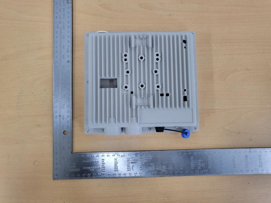
Click to zoom
Application Details
- Equipment Class
- JAD - Part 15 Class A Digital Device
- Date of Grant
- Jul 30, 2023
- Application Purpose
- Original Equipment
- Date of Application
- Jul 30, 2023
- Equipment Note
- 5G NR-U wireless Bridg
- Company
- Miliwave Co., Ltd.
- Country
- South Korea
Documents & Files
Document Text
Text extracted from the exhibit documents filed with the FCC. Open a document above to read the original.
Users Manual
MWC-915 User Manual 1 / 6 MWC-915 User Manual 5G NR-U Wireless Bridge Rev. 1.1 2023-07-12 MWC-915 User Manual 2 / 6 Revision History Date Written by Rev. Description 23.07.07 Sun.Lee 1.0 MWC-915 User manual v1.0 -Pre 23.07.12 Sun.Lee 1.0 MWC-915 User manual v1.1 -Release Address: Room 504, 106-40 Gwahakdnji-ro, Gangneung-si, Gangwon-do. 25440 KOREA. http://www.miliwave.co.kr/ Tel. 070-8825-0630 Fax. Email: [email protected] Copyright © Miliwave Inc. 2020. All rights reserved. No part of this document may be reproduced or transmitted in any form or by any means without prior written consent of Miliwave Co., Ltd. All specification supplied herein are subject to change without notice at any time. MWC-915 User Manual 3 / 6 1.Introduction 1.1 Overview The MWC-915 5G NR-U Wireless Bridge uses the 60GHz radio frequency band to form a wireless bridge with a transmission rate of 2Gbps in both directions. It supports IEEE 802.11ad Standard and can use Ch1~Ch6. It has an SFP port supporting either 1Gbps or 2.5Gbps and one 2.5 Giga Ethernet LAN port interface. And Passive PoE operation using LAN port is possible. (Type 48V) For more information, please contact your Miliwave ([email protected]) < Figure 1. MWC-915 > MWC-915 User Manual 4 / 6 1.2 Abbreviations and Acronym Definitions 2.0 Technical Specifications Parameter Description SOC Dual core ARMv7 Cortex-A9 PoE Passive PoE (Typ 48V) Operating Frequency 802.11 ad : CH1, CH2, CH3, CH4, CH5, CH6 57.24GHz ~ 70.20GHz Transmit Power(max.) 38 dBm @ MCS1 (ANT Beamforming Index 3) Input Voltage Voltage: 24V(typ), Current: 1000mA Power Consumption Data Transfer mode: Typical 20W ( at Max. Power ) Operating Temperature -30ºC ~ +70ºC Storage Temperature 10°C~+40°C Operating Humidity 5%~95% Storage Humidity 5%~95% Volume (L x W x H) 200 x 220 x 57 mm 색상 Ivory Weight Typical 1.2kg Input / Output Port RJ45 2.5 GbE x1 SFP x1 24V DC port(2-pin) x1 Acronym Definition GbpsGiga bits per second GHzGiga Hertz IEEEInstitute of Electrical and Electronics Engineers LEDLight Emitting Diode LoSline-of-sight MbpsMega bits per second MCSModulation and Coding Scheme MHzMega Hertz PTMPPoint-to-multipoint Communication QAMQuadrature amplitude modulation MWC-915 User Manual 5 / 6 3.0 Web UI user guide 3.1 Login 1. Open your web browser, then go to https://192.168.1.1. 2. Enter the device login username and password. The default username and password are as follows: Username: admin Password: admin 1. Your device’s home page (or dashboard) should be displayed. 3.2 Device Overall Status 3.3 Wireless Status MWC-915 User Manual 6 / 6 3.4 Password Change 3.5 IP Network Settings 3.5 Wireless Setting 4.0 Installation It is installed with power supply through 24VDC. And the Passive PoE(Typ 48V) function supported. 5.0 FCC Statement This device complies with Part 15 of the FCC Rules. Operation is subject to the following two conditions: (1) This device may not cause harmful interference, and (2) this device must accept any interference received, including interference that may cause undesired operation. FCC Caution: Any changes or modifications not expressly approved by the party responsible for compliance could void the user's authority to operate this equipment. The device must be installed such that a minimum separation distance of at least 25.15 cm is maintained between the radiator (antenna) and all persons at all times. This equipment has been tested and found to comply with the limits for a Class A digital device, pursuant to part 15 of the FCC Rules. These limits are designed to provide reasonable protection against harmful interference when the equipment is operated in a commercial environment. This equipment generates, uses, and can radiate radio frequency energy and, if not installed and used in accordance with the instruction manual, may cause harmful interference to radio communications. Operation of this equipment in a residential area is likely to cause harmful interference in which case the user will be required to correct the interference at his own expense.
Attestation Statements
Certification designating a U.S. Agent for service of process: As required by section 2.911(d)(7), the applicant must designate a contact located in the United States for purposes of acting as the applicant's agent for service of process, regardless of whether the applicant is a domestic or foreign entity. An applicant located in the United States may designate itself as the agent for service of process. In either scenario, the designation of the U.S. agent for service of process should be provided as an attachment to the equipment authorization application. The applicant must provide a written certification, which must: i. Be signed by both the applicant and designated agent for service of process, if the agent is different from the applicant. ii.Acknowledge the applicant's consent and the designated agent's obligation to accept service of process. iii.Provide a physical U.S. address and email for the designated agent iv.Acknowledge the applicant's acceptance to maintain an agent for no less than one year after the grantee has terminated all marketing and importation or the conclusion of any Commission-related proceeding involving the equipment. Unofficial information provided by FCC personnel on February 14, 2023, via the monthly call with the TCB Council: The Agent for Process of Service: • cannot be a TCB or affiliated with a TCB (e.g. could not be a person who works for a TCB or a company that owns or is owned by the TCB) • cannot be a [FCC recognised) Lab or affiliated with a test lab (e.g. could not be a person who works for a Lab or a company that owns or is owned by the Lab) • Agent can be Individual Entity or a Company Entity • Agent Entity must be located in US, US address/phone • Entity acting as Agent must have FRN (best practice, put FRN on Agent Letter) • Agent letter does not have to be FCC ID specific, can be general Agent for Grantee For devices being marketed or for which marketing has ceased for less than 1 year, if the Agent for Process of Service changes, then for every TC Number the TCB must request the FCC to put application into Audit Mode and Agent Letter needs to be updated (superseded). NOTE: The U.S. Agent for Service of Process should not be confused with the authorized agent used for signing the 731 form, other cover letters within the application, and/or the agent who may interface with theTCB. Miliwave Co., Ltd. xxxx miliwave 504, 106-40 Gwahakdanji-ro, Gangneung-si, Gangwon-do, 25440 South Korea ATTENTION: U.S. Agent Designation for Service of Process Federal Communications Commission Authorization and Evaluation Division 7435 Oakland Mills Road Columbia, MD 21046 USA REGARDING: FCC Certification - Section 2.91 l(d)(7) Infonnation Designated U.S. Agent Company Name: Approve-IT, Inc. Contact Name: Nathan Grinager Street Address: 8011 34 th Ave South, Suite 342 City/Province/Zip: Bloomington, MN 55425 Telephone No: 651-247-1678 Email: [email protected] FRN #: 0027533835 This letter is to confinn that we ("the Designated U.S. Agent) have accepted the responsibility to act as the Designated U.S. Agent for Service of Process as required b y section 47 CFR 2.91 l(d)(7) on behalfofthe Applicant noted below. U .S. Agent Signature: Date: Signed by (Printed Nameffitle): Nathan Grinager / C o-President *This letter is valid indefinitely for aU applications submitted within the period of The Applicant confirms i ts explicit consent and acknowledges that they must maintain an agent for no less than one year after tenninating all marketing and importation OR the conclusion of any Commission- related proceeding involving the equipment. The applicant further acknowledges their responsibility to infonn the FCC whenever the Designated U.S. Agent infonnation above changes. Applicant Company name: Miliwave. F CC ID: 2A VCWMWC-915 Contact Name: Ken.Jung Street Address: R oom504, 106-40 Gwahakdanji-ro, City/Province/Zip: Gangneung-si, Gangwon-do, 25440 KOREA Telephone No: 82-10-4101-5453 Email: k [email protected] Applicant Signature: Date:12. July. 2023 Signed by (Printed Nameffitle): Ken Jung/ Principal HW Engineer 07/27/2023 - 07/26/2024 J uly 27, 2023
External Photos
Model Name : MWC-915 (FCC ID : 2AVCWMWC-915) Pages: 1 / 4 Photographs of EUT Front View of Product Rear View of Product Model Name : MWC-915 (FCC ID : 2AVCWMWC-915) Pages: 2 / 4 Right side View of Product Left side View of Product Model Name : MWC-915 (FCC ID : 2AVCWMWC-915) Pages: 3 / 4 Top View of Product Bottom View of Product Model Name : MWC-915 (FCC ID : 2AVCWMWC-915) Pages: 4 / 4 Port View of Product
Internal Photos
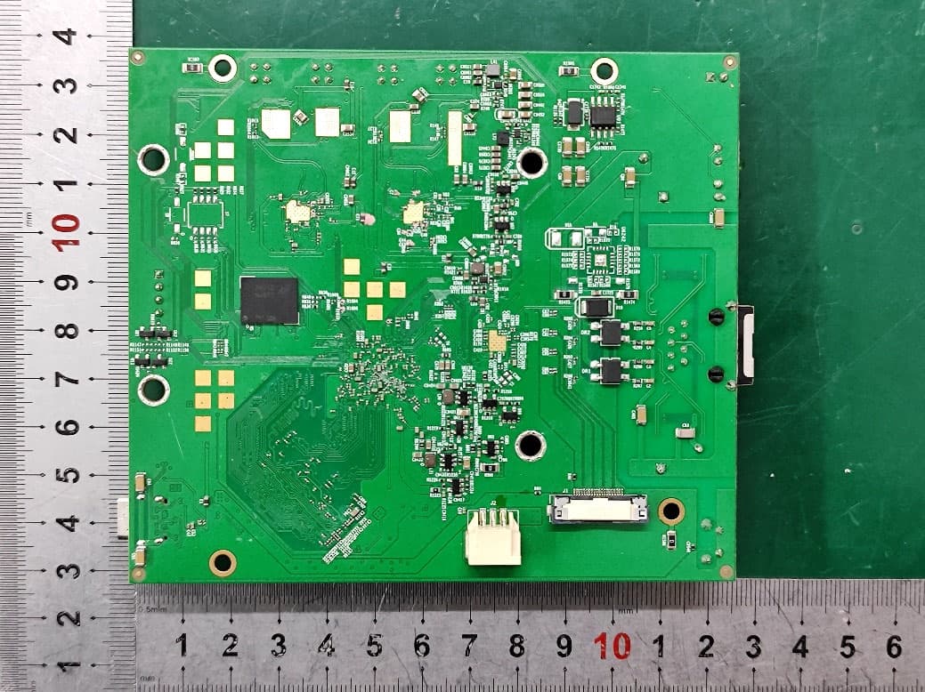
Model Name : MWC-915 (FCC ID : 2AVCWMWC-915) Pages: 1 / 3 Photographs of EUT Inside View of Product Model Name : MWC-915 (FCC ID : 2AVCWMWC-915) Pages: 2 / 3 Front View of Main Board Rear View of Main Board Model Name : MWC-915 (FCC ID : 2AVCWMWC-915) Pages: 3 / 3 Front View of Sub Board Rear View of Sub Board
Test Report
시 점 확 인 필 정 부 시 점 확 인 센 터 진본 2023-07-25 10:12:31 KST Report No.: DREKFCC2307-0102 (FCC ID : 2AVCWMWC-915) This test report is prohibited to copy or reissue in whole or in part without the approval of Dt&C Co., Ltd. TRF-EM-243(00)230309 Pages: 2 / 42 CONTENTS 1. General Remarks ...................................................................................................................... 3 2. Test Laboratory ......................................................................................................................... 3 3. General Information of EUT...................................................................................................... 4 4. EUT Operations and Test Configurations ............................................................................... 5 4.1 Principle of Configuration Selection ....................................................................................... 5 4.2 EUT Operation Mode ............................................................................................................. 5 4.3 Test Configuration Mode ........................................................................................................ 5 4.4 Supported Equipment ............................................................................................................ 6 4.5 EUT In/Output Port ................................................................................................................ 6 4.6 Test Voltage and Frequency .................................................................................................. 6 5. Test Summary ........................................................................................................................... 7 6. Test Environment ...................................................................................................................... 8 7. Test Results : Emission............................................................................................................ 9 7.1 Conducted Disturbance ......................................................................................................... 9 7.2 Radiated Disturbance .......................................................................................................... 10 8. Revision History...................................................................................................................... 42 Report No.: DREKFCC2307-0102 (FCC ID : 2AVCWMWC-915) This test report is prohibited to copy or reissue in whole or in part without the approval of Dt&C Co., Ltd. TRF-EM-243(00)230309 Pages: 3 / 42 1. General Remarks This report contains the result of tests performed by : Dt&C Co., Ltd. 42, Yurim-ro, 154 beon-gil, Cheoin-gu, Yongin-si, Gyeonggi-do, Korea http://www.dtnc.net Tel: +82-31-321-2664 Fax: +82-31-321-1664 2. Test Laboratory Address of Laboratory Branch site 42, Yurim-ro 154 beon-gil, Cheoin-gu, Yongin-si, Gyeonggi-do, Korea Satellite facilities-1 46, Yurim-ro 154 beon-gil, Cheoin-gu, Yongin-si, Gyeonggi-do, Korea Satellite facilities-2 38, Yurim-ro 154 beon-gil, Cheoin-gu, Yongin-si, Gyeonggi-do, Korea Satellite facilities-3 28, Baengnyeong-ro 20 beon-gil, Cheoin-gu, Yongin-si, Gyeonggi-do, Korea Dt&C Co., Ltd. has been accredited / filed / authorized by the agencies listed in the following table; Certificate Nation Agency Code Remark Accreditation Korea KOLAS 393 ISO/IEC 17025 South Africa SABS 0006 ISO/IEC 17025 Ghana NCA NCA agreement 23rd,Oct,2018 - Site Filing USA FCC KR0034 Designation Canada IC KR0034 Designation Japan VCCI C-11427, R-13385, R-14076, R-14180, R-14496, T-11442, G-10338, G-10754, G-10815, G-20051 Registered Certification Korea KC KR0034 Designation Germany TUV CARAT 089112 0010 Rev.00 ISO/IEC 17025 Russia RMRS 22.03.01.01196.296 ISO/IEC 17025 Quality control in the testing laboratory is implemented as per ISO/IEC 17025 which is the “General requirements for the competent of calibration and testing laboratory”. Report No.: DREKFCC2307-0102 (FCC ID : 2AVCWMWC-915) This test report is prohibited to copy or reissue in whole or in part without the approval of Dt&C Co., Ltd. TRF-EM-243(00)230309 Pages: 4 / 42 3. General Information of EUT Applicant Miliwave Co., Ltd. Room504, 106-40 Gwahakdanji-ro, Gangneung-si, Gangwon-do, 25440 KOREA Manufacturer Miliwave Co., Ltd. Room504, 106-40 Gwahakdanji-ro, Gangneung-si, Gangwon-do, 25440 KOREA Product Name 5G NR-U wireless Bridge Model Name MWC-915 Add Model Name None Add Model Difference None Software Version 1 Hardware Version 1 Maximum Internal Frequency 7 0200 MHz Rated Power DC 24 V, POE FCC ID 2AVCWMWC-915 RF Module Name MWC-740m Remarks RF Frequency : 57.24 ~ 70.20 GHz (CH1~CH6) It is a device that is registered as a radio wave suitable for business use (Class A), so please be careful about this point by the seller or the user, and it is intended for use outside the house. Related Submittal(s) / Grant(s) Original submittal only Report No.: DREKFCC2307-0102 (FCC ID : 2AVCWMWC-915) This test report is prohibited to copy or reissue in whole or in part without the approval of Dt&C Co., Ltd. TRF-EM-243(00)230309 Pages: 5 / 42 4. EUT Operations and Test Configurations 4.1 Principle of Configuration Selection Emission : The equipment under test (EUT) was configured to measure its highest possible radiation level. The test modes were adapted accordingly in reference to the instructions for use. For each testing mode different configurations were used, Refer to the individual tests. 4.2 EUT Operation Mode No. Mode Description 1 DC EUT receives 24 V from DC POWER SUPPLY EUT is connected to an external PC via LAN and communicates data EUT uses the CMD program installed on the PC to check and test the operation of the LAN,SFP ports and wireless functions through PING TEST. 2 POE EUT receives power from POE injector EUT is connected to an external PC via LAN and communicates data EUT uses the CMD program installed on the PC to check and t…
Text truncated - open the document above for the full version.
Test Setup Photos
Model Name : MWC-915 (FCC ID : 2AVCWMWC-915) Pages: 1 / 8 Test setup photo Radiated disturbance at (30 ~ 1 000) MHz Test configuration mode 1 EUT Operation mode 1 Model Name : MWC-915 (FCC ID : 2AVCWMWC-915) Pages: 2 / 8 Radiated disturbance at (1 ~ 6) GHz Test configuration mode 1 EUT Operation mode 1 Model Name : MWC-915 (FCC ID : 2AVCWMWC-915) Pages: 3 / 8 Radiated disturbance at (6 ~ 18) GHz Test configuration mode 1 EUT Operation mode 1 Model Name : MWC-915 (FCC ID : 2AVCWMWC-915) Pages: 4 / 8 Radiated disturbance at (18 ~ 40) GHz Test configuration mode 1 EUT Operation mode 1 Model Name : MWC-915 (FCC ID : 2AVCWMWC-915) Pages: 5 / 8 Radiated disturbance at (30 ~ 1 000) MHz Test configuration mode 2 EUT Operation mode 2 Model Name : MWC-915 (FCC ID : 2AVCWMWC-915) Pages: 6 / 8 Radiated disturbance at (1 ~ 6) GHz Test configuration mode 2 EUT Operation mode 2 Model Name : MWC-915 (FCC ID : 2AVCWMWC-915) Pages: 7 / 8 Radiated disturbance at (6 ~ 18) GHz Test configuration mode 2 EUT Operation mode 2 Model Name : MWC-915 (FCC ID : 2AVCWMWC-915) Pages: 8 / 8 Radiated disturbance at (18 ~ 40) GHz Test configuration mode 2 EUT Operation mode 2
Contact Information
Applicant
Ken Jung(CTO (Chief Technology Officer))
Test Firm
Dt&C Co., Ltd.Lee Sang-Wook
Technical Specifications
| # | Rule Parts | Frequency Range | Power Output |
|---|---|---|---|
| 1 | 15B | - | - |
Other Applications from Miliwave Co., Ltd.
2AVCWMWC-708
Apr 10, 2024Wireless Router
Equipment Class
DTS - Digital Transmission System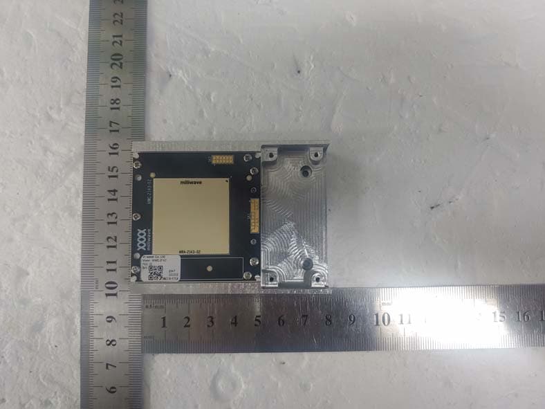
2AVCWMWC-2143
Feb 13, 20245G NR-U Wireless Bridge
Equipment Class
DXX - Part 15 Low Power Communication Device Transmitter
2AVCWMWC-936
Sep 24, 20235G NR-U Wireless Bridge
Equipment Class
DXX - Part 15 Low Power Communication Device Transmitter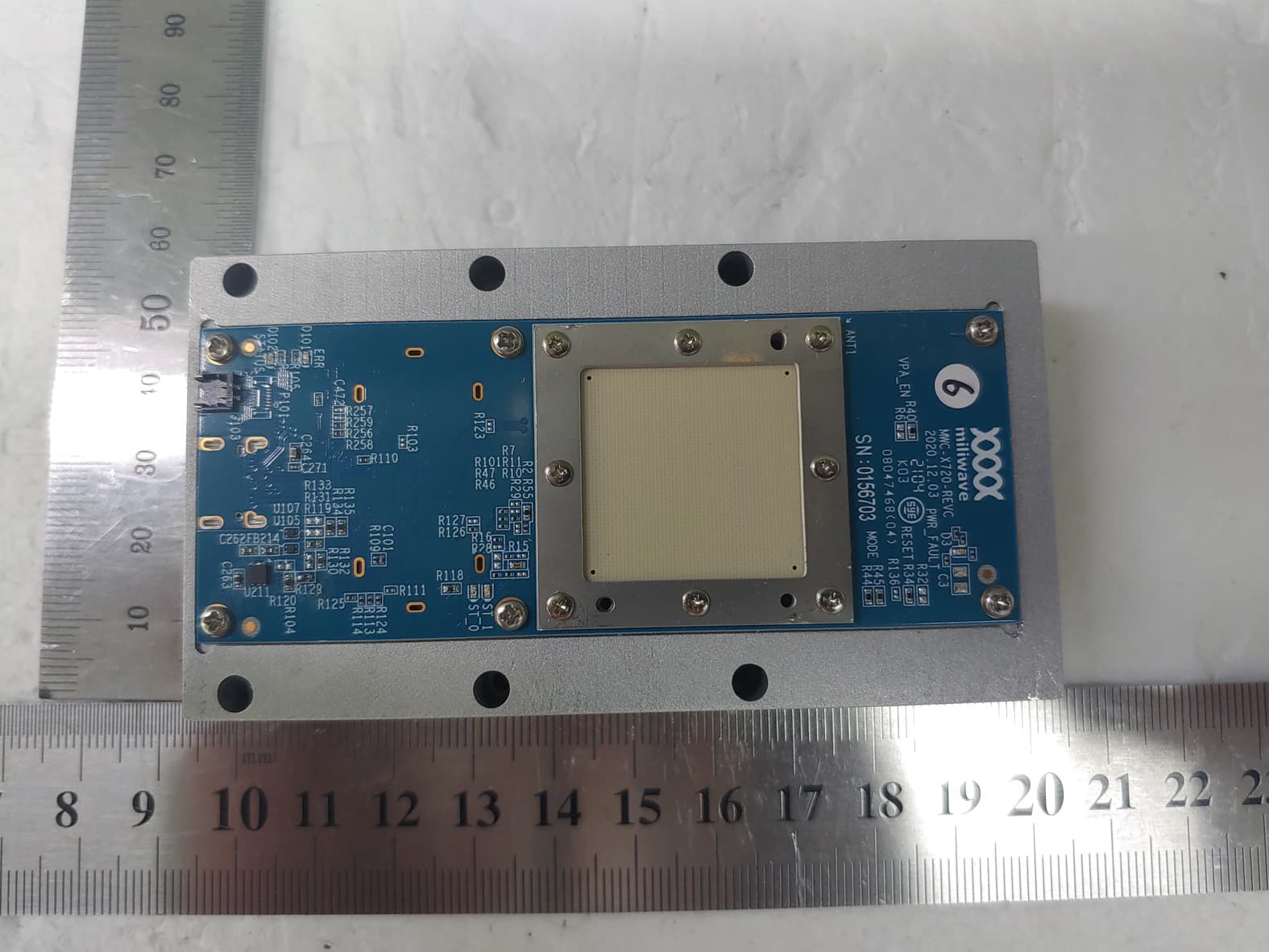
2AVCWMWC-720
Jul 29, 202160GHz RF/BB Module with USB3.0 interface
Equipment Class
DXX - Part 15 Low Power Communication Device Transmitter
2AVCWMWC-713
Jan 03, 2021IEEE802.11ad 60GHz Module
Equipment Class
DXX - Part 15 Low Power Communication Device Transmitter