2AWAA-MS735MHThermal Imager
ZHEJIANG DALI TECHNOLOGY CO., LTD
Click to zoom
Application Details
- Equipment Class
- DTS - Digital Transmission System
- Date of Grant
- Jan 09, 2024
- Application Purpose
- Original Equipment
- Date of Application
- Jan 09, 2024
- Equipment Note
- Thermal Imager
- Frequency Range
- 2412.00000000 - 2462.00000000
- Country
- China
Documents & Files
Document Text
Text extracted from the exhibit documents filed with the FCC. Open a document above to read the original.
Users Manual
Quick Start Guide MS735MH Keys & Interfaces Image mode Scene mode Palette Figure 1 Main Interface Low power consumption mode External HDMI Fog mode Wireless Hot-spot Zoom status Memory capacity Battery level System Time Figure 2 Bottom right status bar Keys instruction: Power Long press for 3 seconds to turn on/off the thermal imaging camera, the green indicator light of the device is on after turning on. Short press for image correction, and press any key to wake up after hibernation. Menu Long press to enter the main menu. Short press to switch the image mode. Photo Short press to take photos. Long press to record videos. Up Short press to switch between large and small field of view in IR, short press to switch the fog mode in visible light. Long press to zoom in under visible light, and increase focus under IR/fusion. Down Short press to auto focus. Long press to zoom out under visible light, and decrease focus under IR/fusion. Up + Down Key Combination + Long press to turn on/off laser rangefinding. Menu + Photo key combination + Long press to turn on/off visible indication laser. Figure 3 Menu Interface Keys instruction: Menu Short press to confirm/enter the next level menu. Photo Short press to return to the previous level menu. Long press to return and exit the user menu. Up Short press to switch up/increase parameters. Long press to quickly switch up/increase parameters. Down Short press to switch down/reduce parameters. Long press to quickly switch down/reduce parameters. Figure 4 Infrared menu interface Hotspot tracking: After opening, the main interface will display a prompt for the highest temperature on the screen Scene mode: natural, enhanced, and highlighted to adapt to different weather and scenes Pseudo-color: 7 kinds of pseudo-color can be selected. Contrast: Adjust the contrast of IR image Brightness: Adjust the brightness of the infrared image. Red display trigger value: Adjust the red display trigger value of infrared images Figure 5 Visible light menu interface Visible Light Enable: Enable to use the function of visible light after opening Contrast: Adjustable contrast of visible light, default to 128 Brightness: Adjustable brightness of visible light, default to 128 Figure 6 Shimmer menu interface Shimmer Enable: when turned on, the image modes of Fusion and Shimmer can be used Figure 7 Positioning menu interface Positioning Enable: When enabled, you can use positioning related functions. Target Guidance: When it is turned on, it will display the target position in the azimuth area of the main interface. Target locking: When enabled, enter the target setting interface, after setting, it can display the radar position of the target point in the main interface. Coordinate system: Global positioning can be displayed in different coordinate modes Figure 8 Compass Menu Interface Compass Enable: When enabled, compass related functions can be used. Angle unit: You can switch different angle unit Magnetic declination: manually set the local magnetic declination to increase the accuracy of the compass. Correction of azimuth, pitch, and roll angles: correct minor deviations caused by environmental factors. Magnetic field space calibration: Enter the compass calibration interface Figure 9 Laser Ranging Menu Interface Ranging Enable: When enabled, ranging-related functions can be used. Target Positioning: When enabled, the coordinates of the target point will be displayed in the upper right corner. Target mode: S elect the number of ranging targets Gate Setting: After setting, the distance measurement results smaller than the set value will be blocked. Figure 10 Playback menu interface Select the file to view by pressing keys. Figure 11 Auxiliary function menu interface Wi-Fi: When enabled, the device can be connected via cell phone. Picture-in-picture: When enabled, the upper area in the main interface will display the enlarged center picture. Digital zoom:The image can be adjusted x1.0-x8.0 Crosshair: When enabled, enter the crosshair setting, the main interface will display the crosshair cursor. Brightness adjustment: Adjust the brightness of the eyepiece LCD screen. Hibernation time: S et the time to hibernate without operating. Low Power Mode: When enabled, some functions will be turned off to maintain long-term battery life. Proximity switch: When enabled, the eyepiece will be automatically turned off when it is not in use. Serial port selection: by setting different modules, personalize them in the host computer. Figure 12 System Setting Menu Interface WiFi mode: Switch the connection mode of the device when WiFi is enabled. Distance unit: Switch all the distance units on the interface. Upgrade: Upgrade the detector version online Format: Format the storage space Reset: Restore factory settings Help file: View the help file on the device side RS232 interface The device comes standard with a one-in-three connection cable with RS232 connector (DC charging, USB data connection, and RS232 connector holder respectively). When charging, the red indicator light is on, and when charging is completed, the green indicator light is on. Video output When in use, dial out the HDMI interface cover, insert the configured HDMI cable, can be accessed to display on the monitor. Precaution Because uncooled infrared telescopes use very sensitive thermal sensors, the lens must not be pointed directly at a source of strong amplitude (e.g. the sun, direct or reflected laser beams, etc.) under any circumstance (power on/off) ,or else permanent damage will be caused to the uncooled infrared telescope! After the laser indication function is enabled, do not shine on the human eye to avoid injury! Without any operation in 5 minutes(time can be customized), the device enters hibernation mode, users can press any key to wake up. Please check the power when the device is used for the first time, and charge the device for three hours after use if ne…
Text truncated - open the document above for the full version.
Attestation Statements
ZHEJIANG DALI TECHNOLOGY CO., LTD Covered Equipment Certification Attestation Letter 1/5/2024 Nemko North America, Inc. 303 River Road Ottawa K1V 1H2 Canada ATTN.: Reviewing Engineer FCC ID: 2AWAA-MS735MH ZHEJIANG DALI TECHNOLOGY CO., LTD (“the applicant”) certifies that the equipment for which authorization is sought is not “covered” equipment prohibited from receiving an equipment authorization pursuant to section 2.903 of the FCC rules. Note: If the equipment for which the applicant seeks authorization is produced by any of the entities identified on the current Covered List , the applicant should include an explanation on why the equipment is not “covered” equipment. ZHEJIANG DALI TECHNOLOGY CO., LTD (“the applicant”) certifies that, as of the date of the filing of the application, the applicant is not identified on the Covered List as an entity producing “covered” equipment. Signature: Name: Shi changbing Company: ZHEJIANG DALI TECHNOLOGY CO., LTD Address: NO639 Binkang Road, Hangzhou, P.R.CHINA 310053 Phone: 8657186483758 Fax: 8657186483758 E-Mail: [email protected]
Attestation Statements
ZHEJIANG DALI TECHNOLOGY CO., LTD * the applicant must designate a contact located in the United States for purposes of acting as the applicant’s agent for service of process, regardless of whether the applicant is a domestic or foreign entity. An applicant located in the United States may designate itself as the agent for service of process. U.S. Agent Designation for Service of Process - Certification Attestation Letter January 4, 2024 Nemko North America, Inc. 303 River Road Ottawa K1V 1H2 Canada ATTN.: Reviewing Engineer FCC ID: 2AWAA-MS735MH Per section 2.911(d)(7) of the FCC rules, ZHEJIANG DALI TECHNOLOGY CO.,LTD (“the applicant”) , FRN: 0029512258 certifies that the equipment for which authorization is sought is designated to the following U.S. Designated agent* for service of process: Company Name: EMCTEK Physical U.S. Company Address: 11788 Big Canyon Ln, San Diego, CA 92131 USA Agent name: Fang Liu Agent Email Address: [email protected] FRN: 0033401829 The above contact person accepts the obligation for service of process. The applicant accepts to maintain an agent for no less than one year after the grantee has terminated all marketing and importation or the conclusion of any Commission-related proceeding involving the equipment. Applicant Signed: Designated Agent Signed: (Required, if different to Applicant): Signed: Signed: Printed name: Shi changbing Printed name: Fang Liu Title: Manager Title: / Company Name: ZHEJIANG DALI TECHNOLOGY CO., LTD Company Name: EMCTEK Date: December 27, 2023 Date: January 5, 2024 FRN Code: 0029512258 FRN Code: 0033401829
Cover Letter(s)
ZHEJIANG DALI TECHNOLOGY CO., LTD Date: 2024.01.05 FCC ID: 2AWAA-MS735MH Dear Sir/Madam, We, ZHEJIANG DALI TECHNOLOGY CO., LTD Hereby declares the following statement for Federal Communications Commission, All these models are identical in the same in structure/host enclosure, internal circuitry/PCB components, hardware/software, The only difference is sales channels, GPS and compass functions. Product name: Thermal Imager Model no.: MS735MH, MS735, S735MH, S735 Sincerely, Signature: Name: Shi changbing Company: ZHEJIANG DALI TECHNOLOGY CO., LTD Address: NO639 Binkang Road, Hangzhou, P.R.CHINA 310053 Phone: 8657186483758 Fax: 8657186483758 E-Mail: [email protected]
Cover Letter(s)
ZHEJIANG DALI TECHNOLOGY CO., LTD Date: 2024.01.15 Equipment Autorisation Division Federal Communications Commission 7435 Oakland Mills Road Columbia, MD 21046 FCC ID:_2AWAA-MS735MH ___ Product Name:__Thermal Imager ________ Request for Confidentiality Pursuant to Sections 0.457 and 0.459 of the commissions rules, we hereby request that the following documents be held confidential: (List here the documents for which you are seeking confidentiality – for example ...) • Schematics • Block Diagram • Operation Description • Tune-up power table These materials contain trade secrets and proprietary information and are not customarily released to the public. The public disclosure of this information might be harmful to the company and provide unjustified benefits to our competitors. Signature: Name: Shi changbing Company: ZHEJIANG DALI TECHNOLOGY CO., LTD Address: NO639 Binkang Road, Hangzhou, P.R.CHINA 310053 Phone: 8657186483758 Fax: 8657186483758 E-Mail: [email protected]
Cover Letter(s)
ZHEJIANG DALI TECHNOLOGY CO., LTD \\192.168.1.200\sz-ctc\09_工程部\RF实验室\2023年案件\10月\CTC230926-005 通鉴 MS735MH RED & FCC ID\1.资料\1.3 申请资料 \Letter\POA_Letter_140225.docx Equipment Autorisation Division Federal Communications Commission 7435 Oakland Mills Road Columbia, MD 21046 Date: 2024.01.05 SUBJECT: FCC Application for FCC ID: 2AWAA-MS735MH To Whom It May Concern: We, the undersigned, hereby authorize _ Titto Zhao _ at _CTC Laboratories, Inc. on our behalf, to apply to the Federal Communications Commission on our equipment. Any and all acts carried out by _ Titto Zhao _ on our behalf shall have the same effect as acts of our own. This is to advise that we are in full compliance with the Anti- Drug Abuse Act. We, the applicant, are not subject to a denial of federal benefits pursuant to Section 5301 of the Anti-Drug Act of 1988, 21 USC853a, and no party to the application is subject to a denial of federal benefits pursuant to that section. Regards, Signature: Name: Shi changbing Company: ZHEJIANG DALI TECHNOLOGY CO., LTD Address: NO639 Binkang Road, Hangzhou, P.R.CHINA 310053 Phone: 8657186483758 Fax: 8657186483758 E-Mail: [email protected]
Cover Letter(s)
ZHEJIANG DALI TECHNOLOGY CO., LTD Date: 2024.01.05 FCC ID: 2AWAA-MS735MH Dear Sir/Madam, We, ZHEJIANG DALI TECHNOLOGY CO., LTD Hereby declares the Product name: Thermal Imager, Model no.: MS735MH, MS735, S735MH, S735, Have done SDOC certification. Sincerely, Signature: Name: Shi changbing Company: ZHEJIANG DALI TECHNOLOGY CO., LTD Address: NO639 Binkang Road, Hangzhou, P.R.CHINA 310053 Phone: 8657186483758 Fax: 8657186483758 E-Mail: [email protected]
External Photos
CTC Laboratories, Inc. 1-2/F., Building 2, Jiaquan Building, Guanlan High-Tech Park, Shenzhen, Guangdong, China Tel: +86-755- 27521059 Fax: +86-755- 27521011 Http://www.sz-ctc.org.cn Page 1 of 5 External Photographs Page 2 of 5 Page 3 of 5 Page 4 of 5 Page 5 of 5
ID Label/Location Info
CTC Laboratories, Inc. 1-2/F., Building 2, Jiaquan Building, Guanlan High-Tech Park, Shenzhen, Guangdong, China Tel: +86-755- 27521059 Fax: +86-755- 27521011 Http://www.sz-ctc.org.cn Page 1 of 1 Label Label Location 1.
Internal Photos
CTC Laboratories, Inc. 1-2/F., Building 2, Jiaquan Building, Guanlan High-Tech Park, Shenzhen, Guangdong, China Tel: +86-755- 27521059 Fax: +86-755- 27521011 Http://www.sz-ctc.org.cn Page 1 of 19 Internal Photographs WIFI Antenna Page 2 of 19 Page 3 of 19 Page 4 of 19 Page 5 of 19 Page 6 of 19 Page 7 of 19 Page 8 of 19 Page 9 of 19 Page 10 of 19 Page 11 of 19 Page 12 of 19 Page 13 of 19 Page 14 of 19 Page 15 of 19 Page 16 of 19 Page 17 of 19 Page 18 of 19 Page 19 of 19
Operational Description
Rev ision:S-1 Page 1 of 6 产 品 承 认 书 (SPECIFICATION) 日期/DATE:2022/08/ 23 编号/NUMBER:198438-1 版本/VERSION:A1 客户名称 CUSTOMER:ZHEJIANG DALI TECHNOLOGY CO.,LTD Address: No.639 Binkang Road, Binjiang District, 310053 Hangzhou, P.R.CHINA 客户料号 CUSTOMER P/N: 公司编号: PART MODEL:HZ8438DL-120mm 产品名称: PRODUCTNAME :PCB天线-带背胶 APPROVALOF SUPPLIER 编制DEAWNBY审核CHECKEDBY核准APPROVEDBY 黄浩林国富肖大田 客户承认APPROVEBY CUSTOMER Revision:S-1Page 2 of 6 变更履历 NO版本变更日期变更内容概述变更原因 1A12022.08.23首次发行--------- Revision:S-1Page 3 of 6 1.0PARTNUMBER; SunskyPartnumberFrequencyBandHHPartNumber HZ8438DL2.4GHZ-2.5GHZ 2.0ANTENNATEST 电性能指标ElectricalSpecifications 频率范围FrequencyRange(MHz)2400--2500 频带宽度Bandwidth(MHz)100 输入阻抗InputImpendence(Ω)50 电压驻波比V.S.W.R≤2.0 连接器型号ConnectType一代IPEX Revision:S-1Page 4 of 6 FreqEffiGain (MHz)(%)(dBi) 240048.162.12 241047.62.48 242050.692.31 243047.092.32 244050.332.43 245053.42.57 246053.032.43 247051.492.3 248047.891.93 249055.762.6 250050.582.16 Revision:S-1Page 5 of 6 3.0ENVIRONMENTALSPECIFICATIONS 3.1TEMPERATURE OperatingTemperatureRange:-40 C~+85 C StorageTemperatureRange:-40C~+120C 3.2SALTSPRAYTEST Antennabeexposedina35°C,5%saltfogchamberfor24hoursthenchecktheappearanceand performanceagainstthespecificationsinnormaltemperature. 3.3STATICHUMIDITYTEST Theantennaissubjectedtothefollowingtest: Temperatures:+70°Cand90%--95%RH TestDuration:24Hours Theantennashouldnotundergoanystructuralorfunctionalchangeandremainwithinthe electrical/mechanicalspecification. 4.0PACKAGING Theantennaswillbepackedinbags,Thereare100or200antennasperbag.Thebagsarepackedin corrugatedfibreboardoverbox. 天线图纸 Revision:S-1Page 6 of 6 同轴线图纸 线长:L=120±2mm线径:1.13mm黑色 一端IPEX一代,另一端剥线尺寸:A=2mmB=2mmC=1.5mm
RF Exposure Info
Page 1 of 54 Report No.: S23111305702001 FCC SAR EVALUATION REPORT In accordance with the requirements of FCC 47 CFR Part 2(2.1093), ANSI/IEEE C95.1-1992 and IEEE Std 1528-2013 Product Name: Thermal Imager Trademark: N/A Model Name: MS735MH Family Model: MS735、S735MH、S735 Report No.: S23111305702001 FCC ID: 2AWAA-MS735MH Prepared for ZHEJIANG DALI TECHNOLOGY CO.,LTD No.639 Binkang Road, Binjiang District, 310053 Hangzhou, P.R.CHINA Prepared by Shenzhen NTEK Testing Technology Co., Ltd. 1&5/F, Building C, 1&2/F, Building E, Fenda Science Park, Sanwei Community, Hangcheng Street, Baoan District, Shenzhen ,Guangdong, China Tel. 400-800-6106, 0755-2320 0050, 0755-2320 0090 Website: http://www.ntek.org.cn Page 2 of 54 Report No.: S23111305702001 TEST RESULT CERTIFICATION Applicant’s name .................. : ZHEJIANG DALI TECHNOLOGY CO.,LTD Address .................................. : No.639 Binkang Road, Binjiang District, 310053 Hangzhou, P.R.CHINA Manufacturer's Name ........... : ZHEJIANG DALI TECHNOLOGY CO.,LTD Address .................................. : No.639 Binkang Road, Binjiang District, 310053 Hangzhou, P.R.CHINA Product description Product name ......................... : Thermal Imager Trademark ............................ : N/A Model Name ......................... : MS735MH Family Model .......................... : MS735、S735MH、S735 Standards .............................. : FCC 47 CFR Part 2(2.1093) ANSI/IEEE C95.1-1992 IEEE Std 1528-2013 Published RF exposure KDB procedures This device described above has been tested by Shenzhen NTEK. In accordance with the measurement methods and procedures specified in IEEE Std 1528-2013 and KDB 865664 D01. Testing has shown that this device is capable of compliance with localized specific absorption rate (SAR) specified in FCC 47 CFR Part 2(2.1093) and ANSI/IEEE C95.1-1992. The test results in this report apply only to the tested sample of the stated device/equipment. Other similar device/equipment will not necessarily produce the same results due to production tolerance and measurement uncertainties. This report shall not be reproduced except in full, without the written approval of Shenzhen NTEK, this document may be altered or revised by Shenzhen NTEK, personal only, and shall be noted in the revision of the document. Test Sample Number .............................. : S231113057001 Date of Test Date (s) of performance of tests ............. : Nov. 17, 2023 Date of Issue ........................................... : Nov. 21, 2023 Test Result............................................... : Pass Prepared By : Reviewed By : Approved By : Jack Li (Project Engineer) Aaron Cheng (Supervisor) Alex Li (Manager) Page 3 of 54 Report No.: S23111305702001 ※ ※ Revision History ※ ※ REV. DESCRIPTION ISSUED DATE REMARK Rev.1.0 Initial Test Report Release Nov. 21, 2023 Jack Li Page 4 of 54 Report No.: S23111305702001 TABLE OF CONTENTS 1. General Information ............................................................................................ 6 1.1. RF exposure limits .................................................................................... 6 1.2. Statement of Compliance ........................................................................ 7 1.3. EUT Description ....................................................................................... 7 1.4. Test specification(s) .................................................................................. 8 1.5. Ambient Condition ................................................................................... 8 2. SAR Measurement System ................................................................................... 9 2.1. SATIMO SAR Measurement Set-up Diagram ............................................ 9 2.2. Robot ..................................................................................................... 10 2.3. E-Field Probe .......................................................................................... 11 2.3.1. E-Field Probe Calibration ................................................................. 11 2.4. SAM phantoms ...................................................................................... 12 2.4.1. Technical Data .................................................................................. 13 2.5. Device Holder ........................................................................................ 14 2.6. Test Equipment List ................................................................................ 15 3. SAR Measurement Procedures .......................................................................... 17 3.1. Power Reference ................................................................................... 17 3.2. Area scan & Zoom scan .......................................................................... 17 3.3. Description of interpolation/extrapolation scheme .............................. 19 3.4. Volumetric Scan ..................................................................................... 19 3.5. Power Drift ............................................................................................ 19 4. System Verification Procedure .......................................................................... 20 4.1. Tissue Verification ................................................................................. 20 4.1.1. Tissue Dielectric Parameter Check Results ...................................... 21 4.2. System Verification Procedure .............................................................. 22 4.2.1. System Verification Results .............................................................. 23 5. SAR Measurement variability and uncertainty .................................................. 24 5.1. SAR measurement variability ................................................................. 24 5.2. SAR measurement uncertainty ..........................................................…
Text truncated - open the document above for the full version.
Test Report
CTC Laboratories, Inc. $CNAS$ 1-2/F., Building 2, Jiaquan Building, Guanlan High-Tech Park, Shenzhen, Guangdong, China Tel: +86-755- 27521059 Fax: +86-755- 27521011 Http://www.sz-ctc.org.cn TEST REPORT Report No. ··························: CTC20231924E02 FCC ID································: 2 AWAA-MS735MH Applicant····························: ZHEJIANG DALI TECHNOLOGY CO.,LTD Address·······························: No.639 Binkang Road, Binjiang District, 310053 Hangzhou, P.R.CHINA Manufacturer························: ZHEJIANG DALI TECHNOLOGY CO.,LTD Address·······························: No.639 Binkang Road, Binjiang District, 310053 Hangzhou, P.R.CHINA Product Name······················: Thermal Imager Trade Mark···························: / Model/Type reference·············: MS735MH Listed Model(s) ····················: MS735, S735MH, S735 Standard·····························: FCC CFR Title 47 Part 15 Subpart C Section 15.247 Date of receipt of test sample...: Oct. 07, 2023 Date of testing.......................: Oct. 07, 2023 ~ Nov. 13, 2023 Date of issue.........................: Dec. 20, 2023 Result.................................: PASS Compiled by: (Printed name+signature) Terry Su Supervised by: (Printed name+signature) Eric Zhang Approved by: (Printed name+signature) Totti Zhao Testing Laboratory Name......: CTC Laboratories, Inc. Address...............................: 1-2/F., Building 2, Jiaquan Building, Guanlan High-Tech Park, Shenzhen, Guangdong, China This test report may be duplicated completely for legal use with the approval of the applicant. It should not be reproduced except in full, without the written approval of our laboratory. The client should not use it to claim product endorsement by CTC. The test results in the report only apply to the tested sample. The test report shall be invalid without all the signatures of testing engineers, reviewer and approver. Any objections must be raised to CTC within 15 days since the date when the report is received. It will not be taken into consideration beyond this limit. The test report merely correspond to the test sample. Page 2 of 80 Report No.: CTC20231924E02 CTC Laboratories, Inc. 1-2/F., Building 2, Jiaquan Building, Guanlan High-Tech Park, Shenzhen, Guangdong, China Tel.: (86)755-27521059 Fax: (86)755-27521011 Http://www.sz-ctc.org.cn For anti-fake verification, please visit the official website of Certification and Accreditation Administration of the People’s Republic of China : yz.cnca.cn Table of Contents Page 1. TEST SUMMARY ......................................................................................................................................... 3 1.1. T EST STA N D AR D S ................................................................................................................................................. 3 1.2. R EPORT VERSION ................................................................................................................................................. 3 1.3. T EST DESCRIPTION ............................................................................................................................................... 4 1.4. T EST FACILITY ...................................................................................................................................................... 5 1.5. M EASUREMENT UNCERTAINTY ............................................................................................................................... 5 1.6. E NVIRONMENTAL CONDITIONS ............................................................................................................................... 6 2. GENERAL INFORMATION ............................................................................................................................ 7 2.1. C LIENT INFORMATION ........................................................................................................................................... 7 2.2. G ENERAL DESCRIPTION OF EUT ............................................................................................................................. 7 2.3. A CCESSORY EQUIPMENT INFORMATION .................................................................................................................... 8 2.4. O PERATION S TAT E ................................................................................................................................................ 9 2.5. M EASUREMENT INSTRUMENTS LIST ...................................................................................................................... 10 3. TEST ITEM AND RESULTS ........................................................................................................................... 12 3.1. C ONDUCTED EMISSION ....................................................................................................................................... 12 3.2. R ADIATED EMISSION ........................................................................................................................................... 15 3.3. B AND EDGE EMISSIONS (RA D I AT E D) ...................................................................................................................... 37 3.4. B AND EDGE AND SPURIOUS EMISSIONS (CONDUCTED) ............................................................................................. 50 3.5. DTS BANDWIDTH .............................................................................................................................................. 64 3.6. M AXIMUM CONDUCTED OUTPUT POWER .............................................................................................................. 69 3.7. P OWER SPECTRAL DENSITY .................................................................................................................................. 71 3.8. D UTY CYCLE .................................................…
Text truncated - open the document above for the full version.
Test Setup Photos
CTC Laboratories, Inc. 1-2/F., Building 2, Jiaquan Building, Guanlan High-Tech Park, Shenzhen, Guangdong, China Tel: +86-755- 27521059 Fax: +86-755- 27521011 Http://www.sz-ctc.org.cn Page 1 of 2 Radiated Measurements 30MHz - 1GHz Above1GHz Page 2 of 2 Conducted Emissions
Test Setup Photos
Test Positions Front Side (Separation distance of 0mm) Back Side (Separation distance of 0mm) Left Side (Separation distance of 0mm) Right Side (Separation distance of 0mm) Top Side (Separation distance of 0mm) Bottom Side (Separation distance of 0mm) END
Contact Information
Applicant
shi changbing
Test Firm
CTC Laboratories, Inc.Totti Zhao
[email protected]+8675527521059
Technical Specifications
| # | Rule Parts | Frequency Range | Power Output |
|---|---|---|---|
| 1 | 15C | 2.41 GHz - 2.46 GHz | 48.20 mW |
Other Applications from ZHEJIANG DALI TECHNOLOGY CO., LTD
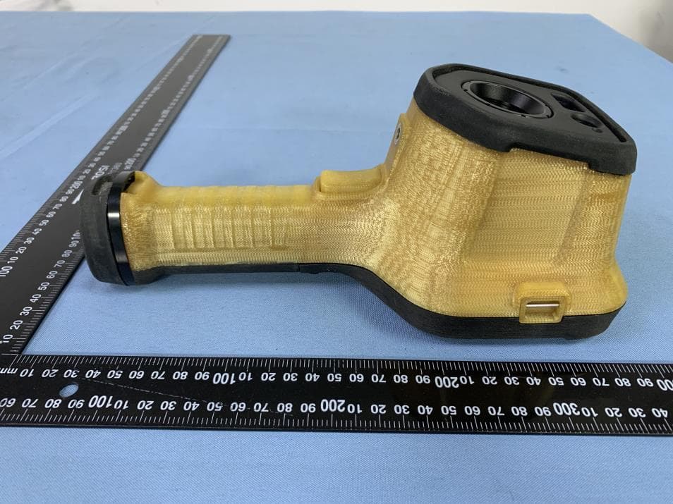
2AWAA-HRYXBSZ-F8
Sep 11, 2024Thermal Imaging Camera
Equipment Class
DTS - Digital Transmission System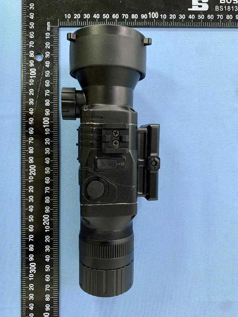
2AWAA-RS6
Sep 01, 2024Thermal Imager
Equipment Class
DTS - Digital Transmission System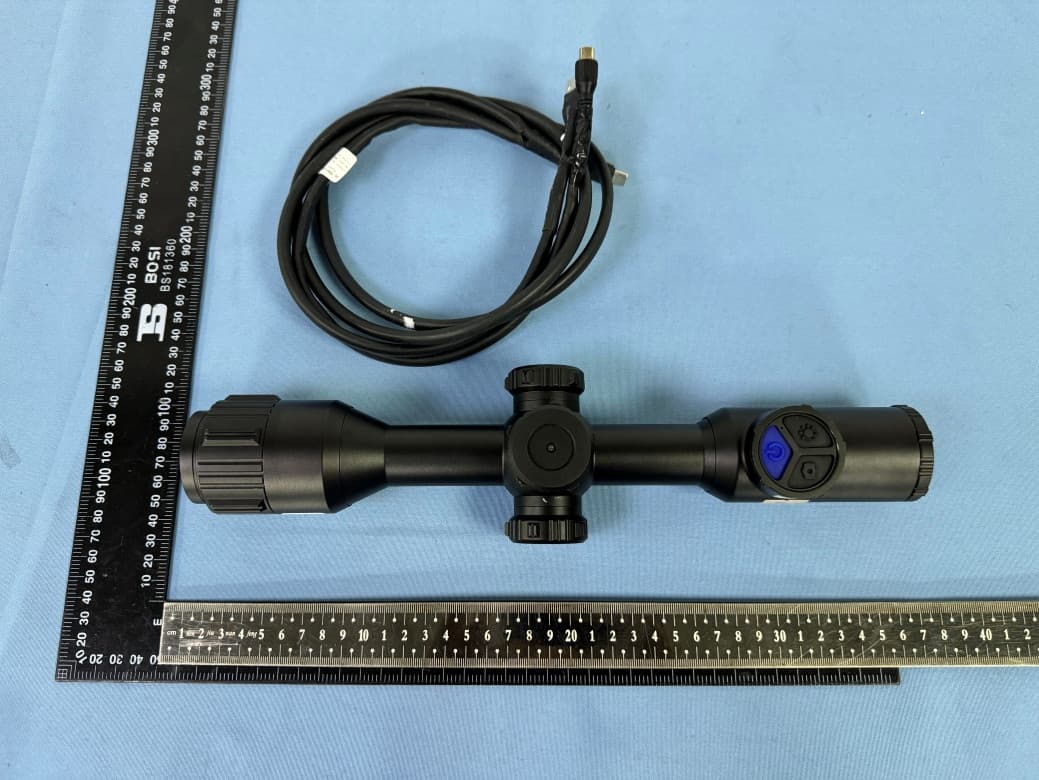
2AWAA-RS7
Aug 01, 2024Thermal Imager
Equipment Class
DTS - Digital Transmission System
2AWAA-T12M
Jan 04, 2024Thermal Imaging Camera
Equipment Class
DTS - Digital Transmission System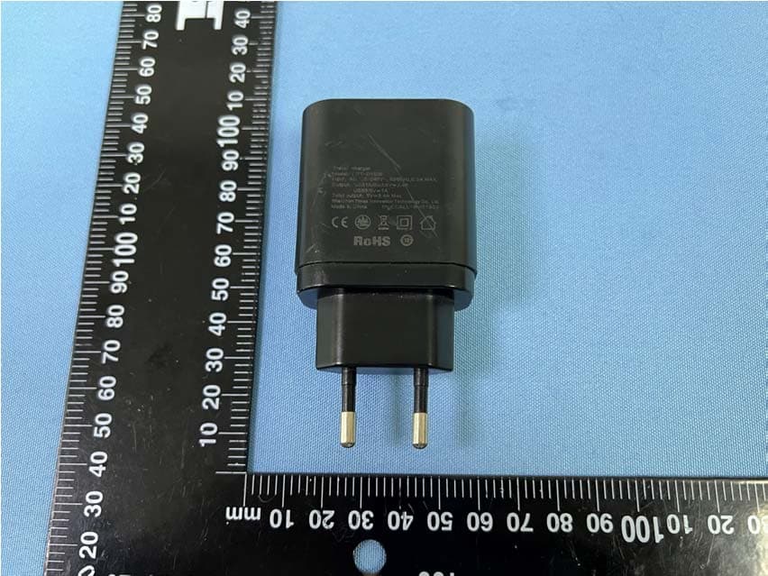
2AWAA-MS715
Dec 12, 2022Thermal Imager
Equipment Class
DTS - Digital Transmission System